Page is loading ...

2018
DHA...EC CP 20 / ...EC O CP S
CONTENTS
Installation, operating and maintenance
instructions
English
1. FOREWORD ............................................................................... 2
2. IMPORTANT INFORMATION .................................................................. 2
3. GENERAL SAFETY INSTRUCTIONS ............................................................. 3
4. ADHERE TO THE FOLLOWING INSTRUCTIONS ................................................... 6
5. PRODUCT INFORMATION .................................................................... 6
6. DELIVERY CONTENTS ....................................................................... 7
7. TECHNICAL DATA ........................................................................... 7
8. DIMENSIONS .............................................................................. 8
9. TRANSPORT AND STORAGE .................................................................. 8
10. ASSEMBLY ................................................................................ 9
11. ELECTRICAL CONNECTION .................................................................. 13
12. COMMISSIONING .......................................................................... 15
13. OPERATION .............................................................................. 15
14. MAINTENANCE AND CLEANING .............................................................. 21
15. LIFETIME AND DISPOSAL ................................................................... 22
16. TROUBLESHOOTING ....................................................................... 22
ruck Ventilatoren GmbH
Max-Planck-Str. 5
D-97944 Boxberg-Windischbuch
Tel. +49 7930 9211-300
Fax +49 7930 9211-166
www.ruck.eu
e original instructions were created in the German
language.
Information updated
print 20.09.2023
Subject to change
Example configuration shown
Roof fan with constant
pressure control
Made in EU

2| DHA...EC CP 20 / ...EC O CP S
EN
Installation, operating and maintenance instructions
2. IMPORTANT INFORMATION
1. FOREWORD
Dear customers,
ank you for choosing our device.
Before operating the unit, please read carefully these installation, operating and maintenance instructions. If you have
any questions, please contact: (Contact details see page 1)
e data provided in these installation, operating and maintenance instructions are for the product description only. A
statement about a certain condition or a suitability for a certain application cannot be derived from our information.
e information does not release the user from his own assessments and examinations.
All rights reserved by the manufacturer, even in the event of industrial property rights.
Any disposal such as copying and distribution rights lies with us.
is manual contains important information on the safe and appropriate assembly, transport, commissioning, operation,
maintenance, disassembly and simple troubleshooting of the product.
e product has been manufactured according to the accepted rules of current technology.
ere is, however, still a danger of personal injury or damage to equipment if the following general safety instructions and
the warnings before the steps contained in these instructions are not complied with.
■Read these instructions completely and thoroughly before working with the product.
■Keep these instructions in a location where they are accessible to all users at all times.
■Always include the operating instructions when you pass the product on to third parties.
2.1. Applicable Documents
e following documents and information on the exhaust fan must be observed in addition to the installation, ope-
rating and maintenance instructions:
Other applicable standards:
■DIN VDE 0100-100
■DIN EN 60204-1
■DIN EN ISO 13857
■DIN EN ISO 12100
■VDMA 24186-1
Available documents at www.ruck.eu
■Installation, operating and maintenance instructions
■Programming instruction FU (three-phase version)
■EC Declarations of conformity
■EC-Declaration of Incorporation (Directive 2006/42/
EC)
■Commissioning report
■Call to Tender
■Dimensioned drawing
■Technical drawing DWG
■Technical drawing DXF
■3D STEP
Nameplate

3
EN
2.3. Warranty and liability
Our devices are manufactured to the highest technical level in accordance with the generally accepted rules of techno-
logy. ey are subject to constant quality controls. Because the products are being constantly developed, we reserve
the right to make changes to the products at any time and without prior announcement. We assume no liability for the
correctness or completeness of these installation, operating and maintenance instructions.
To ensure your warranty claims, it is imperative to provide a commissioning report and a maintenance record.
Warranty and liability claims for personal injury and property damage are excluded if they are due to one or more of
the following causes:
■Improper use
■Improper mounting, commissioning, operation and maintenance
■Operating the device with defective and / or non-functional safety and protective devices
■Failure to observe the instructions regarding transportation, installation, operation and maintenance
■Unauthorized structural changes to the device
■Poor monitoring and replacement of maintenance parts
■Improperly performed repairs
■Disasters and force majeure
3. GENERAL SAFETY INSTRUCTIONS
Planners, plant engineers and operators are responsible for ensuring that the product is installed and operated correc-
tly.
■Use our devices only in perfect technical condition.
■Check the device for obvious defects, such as cracks in the housing or missing rivets, screws, caps or other applica-
tion-relevant defects.
■Only use the device in the power range specified in the technical data and on the nameplate.
■Protection against contact and being sucked in and safety distances should be provided in accordance with DIN EN
13857.
■Generally prescribed electrical and mechanical protection devices are to be provided by the client.
■Safety components must not be bypassed or put out of operation.
■e product may be operated by personnel with limited physical, sensory or mental capacities only if they are su-
pervised or have been instructed by responsible personnel.
■Children must be kept away from the product.
2.2. Provisions and regulations
When properly installed and operated, the device complies with the applicable standards and EU Directive at the
time of its placing on the market.
In addition, observe generally valid, legal and other binding regulations of the European or national legislation as well
as the regulations in your country for accident prevention and environmental protection.
www.ruck.eu |

4| DHA...EC CP 20 / ...EC O CP S
EN
Installation, operating and maintenance instructions
3.2. Improper use
Any use of the product other than described in chapter “Intended use” is considered as improper.
e following points are improper and dangerous:
■Delivery of explosive and flammable media or operation in potentially explosive atmospheres.
■e conveyance of greasy and moist media (over 90% relative humidity).
■Delivery of aggressive and abrasive media.
■Operation without the duct system.
■Operation with closed air connections.
■e use on vehicles, aircrafts and ships.
3.3. Personnel qualifications
Assembly, commissioning, operation, disassembly and service (including maintenance and repair) require basic mecha-
nical and electrical knowledge, as well as knowledge of the appropriate technical terms. In order to ensure operating
safety, these activities may therefore only be carried out by qualified technical personnel or a person under the direc-
tion and supervision of qualified personnel. Qualified personnel are those who can recognize possible hazards and
institute the appropriate safety measures due to their professional training, knowledge, and experience, as well as
their understanding of the relevant conditions pertaining to the work to be done. Qualified personnel must observe the
rules relevant to the subject area.
In this manual, there are safety instructions before the steps whenever there is a danger of personal injury or damage
to the equipment. e measures described to avoid these hazards must be observed.
Safety instructions are set out as follows:
Safety sign (warning triangle) - Draws attention to the risk.
• Type of risk! - Identifies the type or source of the hazard.
»Consequences - Describes what occurs when the safety instructions are not complied with.
→ Precautions - States how the hazard can be avoided.
3.4. Safety instructions in this manual
3.1. Intended use
Our devices are incomplete machineries as defined in the EU Machinery Directive 2006/42/EC (partly completed ma-
chinery). e product is a not ready-for-use machine in terms of the machine directive.
It is intended exclusively for installation in a machine or in ventilation equipment and installations or for combination
with other components to form a machinery or installation. e product may be commissioned only if it is integrated
in the machinery/system for which it is designed and the machinery/system fully complies with the EC machinery di-
rective.
Observe the operating conditions and performance limits specified in the technical data.
Conveying and ambient temperatures must be observed according to the technical data and the nameplate.
Intended use also implies that you have fully read and understood this manual.
Improper use may result in danger to the life and limb of the user or third parties or damage to the system
or other property.

5
!
!
!
!
!
!
!
!
!
!
!
EN
General warning!
Indicates possible hazardous situations. Failure to observe the warnings may result in perso-
nal injury and / or damage to property.
Electricity warning (hazardous voltage)!
Indicates possible hazards due to electricity. Failure to observe the warnings may result in
death, injury and/or damage to property.
Hot surface warning!
Indicates possible hazards due to high surface temperatures. Failure to observe the warnings
may result in personal injury and/or damage to property.
Finger-Crushing Warning!
Indicates possible hazards due to moving and rotating parts. Failure to observe the warnings
may result in personal injury.
Overhead load warning!
Indicates possible hazards due to overhead loads. Failure to observe the warnings may result
in death, injury and/or damage to property.
Follow important information!
Instructions for safe, optimum use of the product.
Safety sign (warning
triangle)
Consequence
• Electricity warning (hazardous voltage)!
»Failure to observe the hazard may result in death,
injury or damage to property.
→ Before performing any work on conductive parts, al-
ways disconnect the unit completely from the electri-
city supply and make sure that it cannot be switched
back on again.
• Never reach into the impeller or other rotating or
moving parts.
»Failure to observe the hazard may lead to serious
injury.
→ Work may only be performed once the impeller has
come to a complete halt.
• Never clean the internal space with flowing water
or a high-pressure cleaner. Do not use aggressive or
easily flammable products for cleaning (impellers/
housing).
→
Only use mild soapsuds. e impeller should be cleaned
with a cloth or brush.
• General warning
»Failure to observe the warnings may result in personal
injury and / or damage to property.
→ Unauthorized repairs may cause personal injury and /
or damage to property, in which case the manufactu-
rer‘s guarantee or warranty will not apply.
• Caution! Burning hazard.
»Failure to observe the hazard may result in personal
injury and/or damage to property.
→ Do not touch the surface until the motor and heater
have cooled.
• Never reach into the impeller or other rotating or
moving parts.
»Failure to observe the hazard may lead to serious
injury.
→ Work may only be performed once the impeller has
come to a complete halt.
www.ruck.eu |

6| DHA...EC CP 20 / ...EC O CP S
EN
Installation, operating and maintenance instructions
4. ADHERE TO THE FOLLOWING INSTRUCTIONS
4.1. General instructions
■Persons who assemble, operate, disassemble or maintain our devices must not be under the influence of alcohol,
drugs or pharmaceuticals that may affect perception and responsiveness.
■Responsibilities for the operation, maintenance and regulation of the product should be clearly determined and
observed so that there can be no unclear areas of responsibility with regard to safety.
4.2. Indications assembly
■Disconnect all of the product‘s poles from the mains before installing the product or connecting or removing plugs.
Make sure that the product cannot be switched back on again.
■Lay cables and lines so that they cannot be damaged and no one can trip over them.
■Information signs must not be changed or removed.
4.3. Indications Commissioning
■Make sure that all electrical connections are either used or covered. Commission the product only if it is installed
completely.
■e power switch must always be fully functional and easy accessible!
■Only authorized personnel is allowed to operate the setting mechanisms of the components or parts, under the
provision that the system is used as intended.
■In an emergency, or if there is a fault, or other irregularities, switch the equipment off and make sure it cannot be
switched back on again.
■e technical data given on the rating plate must not be exceeded.
4.4. Indications during operation
5. PRODUCT INFORMATION
Description:
■Roof fan with constant pressure control
■e temperature of the conveying medium of the individual types can be found in the technical data
■Horizontal discharge
■Backward curved radial impeller
■Motor inside the airflow
■Integrated thermal motor monitoring
■Power switch integrated
■Outdoor installation over heated rooms
■Installation position vertical
■Connection flange dimensions according to DIN 24154R3
■e housing is made of plastic
■Electronically commutated (EC) external rotor motor.
■e roof fan with constant pressure control is used in ventilation sistems to maintain a constant set pressure level.
■e constant pressure control is integrated in the air handling unit housing. It controls the fan speed to reach and
keep the set-point of the differential pressure constant.

7
DHA 190 EC O CP S 01 165071 230V ~ 50/60 121 1,0 50 50 72 76 130426 5,0
DHA 220 EC O CPS 01 166165 230V ~ 50/60 118 1,0 60 60 71 74 130426 5,1
DHA 250 EC CP 20 129702 230V ~ 50/60 204 1,7 60 60 80 85 130426 6,9
DHA 250 EC CP 21 159129 230V ~ 50/60 172 1,4 60 60 73 73 130426 5,7
EN
5.1. Nameplate
ATTENTION! e information on the nameplate must always be observed!
Legend:
■Imax Max. current consumption
■tA / tMMax. ambient temperature / Max. medium temperature
■P1N Rated power consumption
■nNRated speed
■ErP Data ErP Conformity, if required according to Reg. 327/2011
■η Overall efficiency
■N Efficiency at the optimum energy efficiency
■ID Item number
■SN Serial number
Product name
Test date
CE marking
6. DELIVERY CONTENTS
■1 x roof fan with constant pressure control
■1 x Installation, operating and maintenance instructions
■EC Declarations of conformity
■EC-Declaration of Incorporation (Directive 2006/42/EC)
Insulation class motor
EAC marking
7. TECHNICAL DATA
Product name
Item number
Voltage UN
Frequency fN
Rated power consumption PN
Max. motor current Imax
Max. ambient temperature tA
Max. medium temperature tM
Sound power inlet
Sound power outlet
Wiring diagram
Weight
VHz W A °C °C dB(A) dB(A) kg
Air direction arrow
ErP 2015
UKCA marking
Protection class
www.ruck.eu |

8
A B C D E
mm mm mm mm mm
ED
B
C
A
| DHA...EC CP 20 / ...EC O CP S
DHA 190 EC O CP S 01 165071 □321 223 □245 4xØ9Ø213 6x M6x15
DHA 220 EC O CP S 01 166165 □321 223 □245 4xØ9Ø213 6x M6x15
DHA 250 EC CP 20 129702 □321 223 □245 4xØ9Ø213 6x M6x15
DHA 250 EC CP 21 159129 □321 223 □245 4xØ9Ø213 6x M6x15
DHA...EC CP 20 / ...EC O CP S
EN
Installation, operating and maintenance instructions
8. DIMENSIONS
9. TRANSPORT AND STORAGE
Transport and storage should only be performed by specialist personnel in accordance with the assembly and opera-
ting manual and regulations in force.
e following points should be noted and followed:
■Check the delivery according to the delivery note to ensure it is complete and correct and check for any damage.
Any missing quantities or damage incurred during transport shouls.ehrlyd be confirmed by the carrier. No liability is
accepted if this is not observed.
■For weight see technical data
■It should be transported with suitable lifting equipment in the original packaging or on the transport equipment
indicated.
■If transported with a forklift, it should be ensured that the product is resting with the basic profile or base frame
completely on the forks or on a pallet and the product‘s centre of gravity is between the forks.
■e driver must be authorized to drive a forklift.
■Do not go beneath the suspended load.
■Avoid damage or deformation of the housing.
■e product must be stored in a dry area and protected from the weather in the original packaging. Open pallets
should be covered with tarpaulins. Even weatherproof modules should be covered because their weather resistan-
ce is only guaranteed after complete installation. If moisture has penetrated into the original packaging, remove it
immediately.
■Storage temperature between +5 °C and +40 °C. Avoid severe temperature fluctuations.
■If the product has been in storage for more than a year, check the smooth running of impellers and valves by hand.
Product name Item number

9
00
1
4
3
7
2
5
6
EN
10. ASSEMBLY
Assembly work may only be performed by specialist personnel in accordance with the installation and operating ma-
nual and the regulations and standards in force.
e following points should be noted and followed:
■e foundation must be even and levelled. It must not exhibit unevenness or a slope in any direction.
■Set up and align the machine with the aid of a water level. A perfect function of the device can be guaranteed only
if levelled mounted.
■Only suitable installation aids, in accordance with regulations, should be used.
■e device must be installed in such a way that it is easily accessible for maintenance and cleaning purposes.
■e unit should only be installed with authorized and suitable fastening materials at all fastening points.
■Do not distort the unit when installing.
■Just use the indicated mounting and fixing places. No holes should be made in the housing or any screws screwed
into it.
■e duct system must not be supported on the housing.
■For structure-borne sound decoupling, a flexible connection is recommended when connected on a duct system.
■e length of straight tube before fan must be at least 2.5 times the fan diameter
■e pressure measurement hose is placed in the duct to be controlled (va-
cuum side). Check leak tightness while installing.
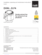
1. Cover
2. Constant pressure control
3. Mounting screws
4. Roof fan
5. Connection cable
6. Pressure measurement hose
7. Roof socket (Accessories)
www.ruck.eu |

10
00
12
00
3
2
4
1
| DHA...EC CP 20 / ...EC O CP S
EN
Installation, operating and maintenance instructions
10.1. Mounting on roof socket (DSF)
10.2. Mounting of electrical connection
Connection power supply:
■Release screws (1)
■Remove cover (2)
■Perform the wiring according to the terminal
diagram
■Fasten the roof fan (2) with screws and washers (3) and (4) on the roof socket (1)

11
Dachventilator
DAS
DAF
DSF
DSF
Rohr
53.651 kg
A4
Do not scale drawing
Protection Mark according to ISO16016
mm
mm
General tolerances DIN ISO 2768-mK
1:22
ruck Ventilatoren
Max-Planck-Str. 5
D-97944 Boxberg
Accesorii DVN
Intern
04 129688
04 129688
52.766 kg
A4
Do not scale drawing
Protection Mark according to ISO16016
mm
mm
General tolerances DIN ISO 2768-mK
1:17
ruck Ventilatoren
Max-Planck-Str. 5
D-97944 Boxberg
Accesorii DVN_4
Intern
04 129688
56.072 kg
A4
Do not scale drawing
Protection Mark according to ISO16016
mm
mm
General tolerances DIN ISO 2768-mK
1:18
ruck Ventilatoren
Max-Planck-Str. 5
D-97944 Boxberg
Accesorii DVN_2
Intern
04 129688
EN
10.3. Installation examples
DSF
DAS
DAF
Tube
Roof fan
DSF
DAS
DAF
Tube
Roof fan
DVK
DSF
DVK
DAF
Tube
Roof fan
DSF - Flat roof socket / Sloped roof socket
Illustrations exemplary
www.ruck.eu |

12
62.736 kg
A4
Do not scale drawing
Protection Mark according to ISO16016
mm
mm
General tolerances DIN ISO 2768-mK
1:22
ruck Ventilatoren
Max-Planck-Str. 5
D-97944 Boxberg
Accesorii DVN_5
Intern
04 129688
57.999 kg
A4
Do not scale drawing
Protection Mark according to ISO16016
mm
mm
General tolerances DIN ISO 2768-mK
1:17
ruck Ventilatoren
Max-Planck-Str. 5
D-97944 Boxberg
Accesorii DVN_8
Intern
04 129688
62.736 kg
A4
Do not scale drawing
Protection Mark according to ISO16016
mm
mm
General tolerances DIN ISO 2768-mK
1:22
ruck Ventilatoren
Max-Planck-Str. 5
D-97944 Boxberg
Accesorii DVN_5
Intern
04 129688
61.304 kg
A4
Do not scale drawing
Protection Mark according to ISO16016
mm
mm
General tolerances DIN ISO 2768-mK
1:17
ruck Ventilatoren
Max-Planck-Str. 5
D-97944 Boxberg
Accesorii DVN_7
Intern
04 129688
| DHA...EC CP 20 / ...EC O CP S
EN
Installation, operating and maintenance instructions
DSS
Tube
Roof fan
DAS
DAF
Tube
Roof fan
DAP
DVK
DAF
Tube
Roof fan
DAS
DAF
DAP
DAS
DAF
DAP
DSS DSS
DVK
DAP
DSS - Socket silencer / Sloped roof socket silencer
Illustrations exemplary

13
EN
e electrical installation may only be carried out by qualified electricians in compliance with the installation, operating
and maintenance instructions and the applicable national regulations, standards and guidelines:
■ISO, DIN, EN and VDE specifications, including all safety requirements.
■Technical connection conditions.
■Safety at work and accident prevention requirements.
is list does not claim to be complete.
Requirements should be applied under one‘s own personal responsibility.
■e electrical connections must be made as shown in the corresponding wiring diagrams and terminal diagrams.
■e type of cable, size of cable and method of laying should be determined by an authorized electrician.
■Low and extra-low voltage cables should be laid separately.
■If no repair switch is integrated in the device, an all-pole mains disconnecting switch with min. 3 mm contact
opening must be provided in the supply line.
■Use a separate cable inlet for each cable.
■Any cable inlets that are not used must be sealed so that it is airtight.
■All cable inlets must have strain relief.
■Create equipotential bonding between the unit and the duct system.
■Check all protective measures after the electrical connection work (earthing resistance, etc.)
■Motor current and motor power must not exceed the values stated on the motor nameplate. e specified max.
fan speed must never be exceeded, otherwise the motor and fan will be destroyed by this overload and dissolved
or flying parts can destroy other components.
11. ELECTRICAL CONNECTION
• Electricity warning (hazardous voltage)!
»Failure to observe the hazard may result in death, injury or damage to property.
→ Before performing any work on conductive parts, always disconnect the unit completely from the electri-
city supply and make sure that it cannot be switched back on again.
6. X3, X4 Open: day-time operation
Closed: night-time operation
7. X5, X6 Open: regulator OFF
Closed: regulator ON
8. Set-point: day 10-990 Pa
9. Set-point: night 10-990 Pa
www.ruck.eu |

14 | DHA...EC CP 20 / ...EC O CP S
EN
Installation, operating and maintenance instructions
11.1. Unit supply cable / Electrical connection / wiring diagram
Connect the mains supply cable as shown in the wiring diagram. For the dimensioning of the line, observe the unit‘s
rating plate and the relevant guidelines. Appropriate protection with correctly dimensioned automatic safety breakers
(circuit protection breaker) must be provided.
e device must be connected according to the wiring diagram. For fans which are controlled by external control de-
vices, the corresponding operating instructions of the manufacturer must be observed.
If a fault current protection switch is used, only AC/DC sensitive RCD protective devices (type B or B+) are permitted.
During operation, electric motors heat up. Under certain circumstances (excessively high ambient or fluid temperatu-
res, heavy contamination, etc.), the motor temperature may exceed the safety limit of the electrically isolated parts.
In case of EC motors an electronic temperature monitoring is present.
11.3. Fault current protection switch
11.2. ermal motor protection
Even when the device is switched off, voltage is applied to terminals and connections. Do not touch the de-
vice for 5 minutes after all-pole disconnection from the mains.
Only potential-free contacts may be connected at terminals X3 and X4, and X5 and X6. Applying an external voltage
can seriously damage the regulator.
e regulations for safety extra-low voltages must be observed.
e maximum pressure in a ventilation plant must not exceed 5000 Pa.
is would result in severe damage to the regulator.
Low voltage control leads must be installed so that they are separated from mains leads.

15
8 8
3 2
9 9
4 1
= 32 x 10 = 320 Pa
= 41 x 10 = 410 Pa
EN
12. COMMISSIONING
Commissioning by trained technical personnel may only be performed after any risk has been ruled out. e
following checks should be performed in accordance with the installation and operating manual and the regu-
lations in force:
■Correctly sealed installation of the unit and duct system.
■Check the duct system, unit and medium lines, if present, remove any foreign bodies if necessary.
■e intake opening and inflow into the unit must be clear.
■Check all mechanical and electrical protection measures (e.g. earthing).
■Voltage, frequency and type of current must correspond with the rating plate.
■e pressure measuring tube will be laid in the duct.
■Setting of the desired differential pressure see 13. Operation
13. OPERATION
CAUTION! Isolate electrical installation!
NIGHT
DAY
Adjust set-point
After removing the cover, you have free access to the pressure regulation circuit board.
Adjust set-point for the desired differential pressure at the two upper decade switches (8).
Switching the regulator on and off
Bridging terminals X5 and X6 switches the constant pressure regulator CON P1000 on, and removing the bridge swit-
ches it off again.
Turning the night mode ON and OFF
By bridging the terminals X3 and X4 the night mode is switched on, by removing the bridge, it is switched off.
Changing day-time set-point
Adjust set-point Day with the decade switches (8).
e.g. 3 2 = 32 x 10 = 320 Pa
Adjusting the night-time set-point
Adjust set-point Night with the decade switches (9).
e.g. 4 1 = 41 x 10 = 410 Pa
13.1. Operation without a control unit
www.ruck.eu |

16
P1 V 3.0
M
4
1
2
A
B3
| DHA...EC CP 20 / ...EC O CP S
EN
Installation, operating and maintenance instructions
13.2. Operation with a control unit (optionally)
ATTENTION: When disconnecting the control unit from the unit after programming, the adjusted set-
points will be deleted. e manually adjusted setpoints by the rotary switch will then apply.
e control unit is used for controlling and entering various functions. e display shows the various operating parame-
ters and error messages. You can select individual menu points or change values with the various buttons.
1) Mode Button
Switches to the control unit parameter menu.
2) ON/OFF Button
Button for switching the unit on or off or switching to menu ma-
nagement.
A) Button A
Buttons for increasing and decreasing the set-point for “DAY”
B) Button B
Buttons for increasing and decreasing the set-point for “NIGHT”
3) Control cable
4) Display
OFF
when regulator on
when regulator off
PA
150 50 0
13.2.1. Adjustment of the control unit parameter
5 sec
M
A
2 sec
M
A
B
or
OFF
DAY NIGHT
P 1 V
1.1
P 2 V1.1
0 ENGLISH
OFF
PA
150 50 0
To be able to make changes to the control unit parameter, you must press the „Mode but-
ton“ (M) for at least 5 seconds. P 1 will appear on the display. Use button A (▲) to change
to your desired parameter.
when regulator on
when regulator off
P 2 Language setting
Use button A (▲) to change to language setting
P 2. Now press button B (▲) and the control
unit will change to input mode. You can now use
buttons A (▲ and ▼) to select the language re-
quired.
Press button B (▲) again to accept the langua-
ge selected.
en press the „Mode button“ (M) for at least 2
seconds. e parameters will be saved and the
menu will close. e Display switches into ope-
rating mode.
Range of values
0 DEUTSCH
(Factory setting)
1 ENGLISH
2 FRANCAIS
3 DANSK
4 ESPAÑOL
5 NEDERLANDS
6 PORTUGUÊS
7 POLSKI
8
9

17
B
A
PA
150 60 150
PA
150 60 150
PA
150 60 150
PA
150 60 150
A
A
A
A
B
B
B
B
EN
13.2.2. Menu functions
OFF
10 sec
Parameter settings Menu
see Section 13.2.3
Status ON / OFF
Press the ON/OFF button (2) to switch the unit on or off. e unit‘s status now appears on
the display with the current values.
DAY – Changing the setting
Use the A buttons on the control unit to increase (▲) or reduce (▼) the
set-point.
(e setting range is limited by parameters P01 and P02.)
e DAY set-point is retained in memory after a power failure.
Status display
NIGHT - Changing the setting
Use the B buttons on the control unit to increase (▲) or reduce (▼) the
set-point.
(e setting range is limited by parameters P01 and P02.)
e NIGHT set-point is retained in memory after a power failure.
Current display
Pressure difference
13.2.3. Parameter settings Menu
10 sec
P 1 MIN-VALUE
5
P 2 MAX-VALUE
990
P 3 P-COMPONENT
5
P 4 PRESSURE CORR
0
P 5 DAY NIGHT
10 100 200
You move to the parameter settings menu menu P by pressing the ON/OFF button, which
must be held down for approx. 10 seconds.
Parameter P01 is displayed on the screen. With the A (▲ and ▼) buttons on the control
unit, the individual P parameters can be called up. Press the „mode button“ (M) once to
return to the starting function.
P 1 Minimum set-point on control unit
Parameter for display and setting of the minimum set-point.
e setting range is from 10 Pa to 500 Pa.
e parameters can be changed with the buttons B (▲ and ▼).
P 2 Maximum set-point on control unit
Parameter for display and setting of the maximum set-point.
e setting range is from 100 Pa to 990 Pa.
e parameters can be changed with the buttons B (▲ and ▼).
P 3 P - component
e setting range is from 5 to 15.
05 = no gain 10 = average gain 15 = high gain
e parameters can be changed with the buttons B (▲ and ▼).
e works setting is 5.
e regulation tends to pulsate at high gain.
P 4 Pressure correction
e works setting is “0”.
e parameters can be changed with the buttons B (▲ and ▼).
Settings between -20 Pa and +20 Pa are possible.
P 5
Control of the decade switches for Day and Night.
e current program version is listed below „P05“.
www.ruck.eu |

18
Bl.
Blatt
Ursp.
Norm
Gepr.
Bearb.
Datum
Name
Datum
Änderung
Zustand
ruck Ventilatoren GmbH
Max-Planck-Strasse 5
D-97944 Boxberg
Tel +49 (0) 7930 9211-300
8
=CONP
CONP 1000Für BDA
CONP 1000
136064_00
S. Kuhbach
26
E
D
C
B
F
A
E
D
C
B
F
A
8765
4
3
2
1
PE
PE
L
L
N
N
Day
Night
X10
X9
X8
X7
X6
X5
X4
X3
X2
X1
Freigabe
enable
day / night
GND
0-10V
Freigabe / enable
Frq.
CON_P 1000
X12
X11
GND
Tacho / Fault
GND
A
B
24V
J1
J2
+
-
A
B
Sollwert erreicht /
setpoint reached
Bl.
Blatt
Ursp.
Norm
Gepr.
Bearb.
Datum
Name
Datum
Änderung
Zustand
ruck Ventilatoren GmbH
Max-Planck-Strasse 5
D-97944 Boxberg
Tel +49 (0) 7930 9211-300
10
=CONP
CONP 1000 CONP 1000
136064_00
S. Kuhbach
26
E
D
C
B
F
A
E
D
C
B
F
A
8765
4
3
2
1
PE
PE
L
L
N
N
Day
Night
X10
X9
X8
X7
X6
X5
X4
X3
X2
X1
Freigabe
enable
day / night
GND
0-10V
Freigabe / enable
Frq.
CON_P 1000
X12
X11
GND
Tacho / Fault
GND
A
B
24V
J1
J2
+
-
05
Adresse = 5
2
Baudrate = 9600
0 = 2400
1 = 4800
2 = 9600
3 = 14400
4 = 19200
Einstellung Adresse und Baudrate
Sollwert erreicht /
setpoint reached
| DHA...EC CP 20 / ...EC O CP S
EN
Installation, operating and maintenance instructions
13.3. Operation with Modbus communication interface
13.3.1. Wiring diagram
13.3.2. Interface information
e device works as a Modbus RTU slave. e interface configuration is 8N1, 9600Baud, slave address 1. e address
and the baud rate can be set, see the following figure. As bus line is recommended a twisted pair data cable with 120
Ohm impedance.
13.3.3. Functions implemented
Function code Name Description
03 Hex Read Hold Register Read device parameter
04 Hex Read Input Register Read current value
06 Hex Write Single Register Write device parameter word by word
10 Hex Write Multiple Register Write several device parameters word by word
To activate Modbus operation, jumper J2 must be set as shown in the following figure.

19
EN
Function code Name Sub-function Description
08 Hex Return Query Dat 00 Send the received message back
08 Hex Restart Communications 01 Restart communication
08 Hex Force Listen Only Mode 04 Switch to listen-only mode
13.3.4. Parameter table
Register
address
Protocol
address Parameter name Value range Data
type
Autho-
rity
40001 0 Reserved integer R/W
40002 1 Min. set-point value 10 - 500 PA integer R/W
40003 2 Max. set-point value 100 - 999 PA integer R/W
40004 3 P - component 5 - 15 integer R/W
40005 4 Pressure correction -20 - 20 PA integer R/W
40006 5 Reserved integer R/W
40007 6 Reserved integer R/W
40008 7 Reserved integer R/W
40009 8 Reserved integer R/W
40010 9 Reserved integer R/W
40011 10 Set-point: day Pressure (PA) integer R/W
40012 11 Set-point: night Pressure (PA) integer R/W
40013 12 day/night switching 0 = Day-time operation 1 = Night-time
operation integer R/W
40034 33 Status and control word See Table below integer R/W
40036 35 Save parameters 12439 Value change after saving under 0 integer R/W
Function Authority Comment
Bit 0 1 = Error present R integer
Bit 1 Reserved R/W
Bit 2 Reserved R/W
Bit 3 Reserved R/W
Bit 4 Reserved R/W
Bit 5 1 = Cancel error R/W With rising slope, error is cancelled
Bit 6 0 = Unit switched ON
1 = Unit switched OFF R/W shut-off with increasing flank
Bit 7 0 = Unit switched ON
1 = Unit switched OFF R/W With rising slope, unit switched ON
Bit 8 Reserved R/W
Bit 9 Reserved R/W
Bit 10 Reserved R/W
Bit 11 Reserved R/W
Bit 12 Reserved R/W
Bit 13 Reserved R/W
Bit 14 Reserved R/W
Bit 15 Reserved R/W
www.ruck.eu |

20 | DHA...EC CP 20 / ...EC O CP S
EN
Installation, operating and maintenance instructions
Example for switching on and off:
To switch on, 128 (decimal) must be written into register 33 (status and control word).
To switch off, 64 (decimal) must be written into register 33 (status and control word).
13.3.5. Current value table
Register
address
Protocol
address Parameter name Value range Data
type
Autho-
rity
30001 0 Reserved integer R/W
30002 1 Room temperature integer R/W
30003 2 Measured pressure Pressure (PA) integer R/W
30004 3 Set day internal switch Pressure (PA) integer R/W
30005 4 Set night internal switch Pressure (PA) integer R/W
30006 5 Reserved integer R/W
30007 6 Reserved integer R/W
30008 7 Reserved integer R/W
30009 8 Reserved integer R/W
30010 9 Reserved integer R/W
30011 10 Reserved integer R/W
30012 11 Control fan 0 - 100 % integer R/W
30013 12 Pressure in range
0 = Pressure difference between setpoint and
measured > 20 Pa
1 = Pressure difference between setpoint and
measured < 20 Pa
integer R/W
30014 13 Set pressure Pressure (PA) integer R/W
30025 24 Error number See Table below integer R/W
Current value table, protocol addresses 24 (error numbers)
Value
0 Reserved
1 Reserved
2 Reserved
3 Reserved
4 Reserved
5 Reserved
6 Reserved
7 Reserved
8 Reserved
9 Reserved
10 Fan defective
11 Reserved
12 Reserved
13 Reserved
14 Reserved
15 Reserved
16 Reserved
17 Reserved
18 Reserved
19 Reserved
20 Reserved
/