Page is loading ...

Texmate, Inc. Tel. (760) 598-98993/31/00 DI-45U Data Sheet (DI2) Page 1
DESCRIPTION
The DI-45U TIGER CUB meter is the most effective solu-
tion to a wide range of measurement and control applications.
With front panel push button commands, the user can setup the
DI-45U TIGER CUB to display a wide variety of input signals,
including DC volts and current, AC volts and current (average
and Trms), thermocouple, 2, 3, or 4 wire 100 ohm platinum
RTDs, four or six wire Strain Gauge signals (load cells and pres-
sure transducers), 4-20mA process signals and frequency. The
DI-45U TIGER CUB also has dual input modules for DC Volts
and DC milliamps.
Input signals may be displayed as voltage or current, or
scaled to read directly in engineering units (eg. PSI, GPM, FPS,
RPM, lbs., degrees, etc.). Scaling in ˚F or ˚C is programmable
from the front panel. With user selectable 3 or 16 readings per
second, the DI-45U TIGER CUB provides fast control response,
true peak readings and a non-isolated analog output signal that
tracks the input signal.
An isolated 5 or 10VDC excitation is available to power pres-
sure transducers and load cells, eliminating the need for an exter-
nal power supply. 24VDC excitation is available on certain input
signal conditioning modules to power process transmitters.
Options include from one to four high isolation relays to im-
plement alarm setpoints programmed by the user. These outputs
can be set to operate above or below the setpoint and in a
latched or non-latching mode. Time delays and hysteresis of the
output are digitally settable. Optional non-isolated analog outputs
of 0-10VDC or 0-20mA (4-20mA) are available to drive chart re-
corders or remote displays. The non-isolated analog output is
scalable from the front panel.
The third simultaneous output option available is logic level
TTL non-isolated serial output, which enables the DI-45U TIGER
CUB meter to communicate with PLC's or personal computers
using the external Texmate Logic To RS232C Isolated Converter.
Baud rates are software selectable from 200 to 19200.
MeterBoss™ software is available to facilitate meter setup
.
SPECIFICATIONS
Input Configuration:........25 single and dual input
modules
Output Options:
Relay ........................Up to two 10A form C and/or
two 5A form A
Analog ......................Non-Isolated 0-20mA (4-20mA)
or 0-10VDC, scalable by user
Communication..........Logic level TTL non-isolated
Display Range: ................ -19999 to +32766 or -19990
to +99990 (dummy zero
selected)
Input Impedance: ............1 Meg Ohm for DCV (Depend-
ing on input module selected)
Internal Resolution: ........16 bit
Common Mode Rejection:
....> 35dB at 50Hz
Conversion Mode: ..........Dual slope; bipolar
Accuracy: ........................±(0.05% of reading + 1 digit)
Conversions per sec: ......
Typically 3, programmable to 16
Temp. Coefficient:............< 80ppm/˚C
Display: ............................7 segment, 0.56" high LEDs,
5 digit, red or green
Polarity: ............................Auto
Decimal Point:..................User programmable
Annunciators: ..................Front panel; one annunciator
per alarm. Annunciators may
also be programmed to
display trend.
Overload Indication: ......Indication "-----"
Case Dimensions: ..........1/8 DIN (96x48x117mm) not
including connectors
Panel Cutout: ..................45x92mm
Case Material: ................Metal sheathed ruggedized plastic
Power Requirements: ....100 to 120VAC or 200 to 240VAC
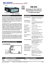
An Economical and Powerful Intelligent Panel Meter
for Monitoring, Measurement and Control Applications
DI-45U TIGER CUB
SMART DIGITAL METER
ORDERING INFORMATION Order Part No.
• DI-45U base unit, standard software, 5 digit red LED display, 100 to 120VAC or 200 to 240VAC
power supply, and plug-in screw terminal blocks (Requires input module. See below).............................................................DI-45U
• Display Option:
High efficiency green LED display ....................................................................................................................................DI-GREEN5
• Metal sheath option for polycarbonate case ..............................................................................................................OP-MTL 96x48
• NEMA 4 lens cover ......................................................................................................................................................OP-N4X/96x48
• Input Options: See page 13.
• Output Options: See page 12.

Texmate, Inc. Tel. (760) 598-9899Page 2 3/31/00 DI-45U Data Sheet (DI2)
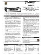
FRONT PANEL FUNCTIONS
UP ARROW
BUTTON
DISPLAY WITH FACEPLATE AND BEZEL
OFF
12
DOWN
ARROW
BUTTON
DISPLAY BOARD WITHOUT FACEPLATE
L1 H1
ANNUNCIATORS
L2 H2
BASIC METER OPERATION
STANDARD PROGRAMMING
The resident software in the DI-45U TIGER CUB has been
designed for maximum user flexibility while maintaining an intel-
ligible programming process. This 'intuitive' software, unique to
the Texmate DI-45U TIGER CUB, allows quick understanding of
the meter's capabilities while allowing the user to be in control.
The software set up can be accomplished via the three front
panel buttons (Prog./Up arrow/Down arrow.) To begin, these
three buttons allow the user access to input scaling (MX+B),
baud rate selection, setting of an address and display bright-
ness. These first selections are then followed by the program-
ming of a series of four 3-digit codes. Each digit within a single
code represents a specific function of the DI-45U TIGER CUB.
The user can customize the meter to their exact needs. If a
function requires change after the initial set up, all previous
selections can be ignored (skipped) and only the specific code
affecting the function in question needs to be changed. This
unique code structure makes software modifications fast and
easy. Texmate has Technical Staff on call to assist you in this
process should the need arise.
MeterBOSSTM SOFTWARE
As an option, Texmate offers MeterBOSS software which can
be accessed through the serial port from your personal comput-
er. This is in addition to our standard DI-45U TIGER CUB meter
package and allows the user to display and modify data direct-
ly on the PC screen. MeterBOSS software is explained fully on
page 9 of this bulletin.
EXAMPLE PROGRAMMING SYMBOLS
Symbol Explanation
PROGRAM BUTTON: This button is used to move from one
program step to the next.
When used simultaneously with the UP ARROW button, it initi-
ates the Programming Mode.
When used simultaneously with the DOWN ARROW button, it
initiates the Setpoint Program.
UP ARROW BUTTON: Increases the value of the displayed
parameter.
DOWN ARROW BUTTON: Decreases the value of the dis-
played parameter.
ANNUNCIATORS: May be programmed to indicate the setpoint
status. They are labeled L2, L1, H1, H2.
PROGRAM LOCKOUT SWITCH: Once the program has been
entered, this switch will not allow any changes to be made
except for the setpoints. If programming is attempted, the DI-
45U TIGER CUB will display 'LOC'. Parameters may still be
viewed but not changed.
SETPOINT LOCKOUT: Once the setpoint values have been
entered this switch will not allow changes to be made except for
the program. If setpoint programming is attempted, the DI-45U
will display 'LOC'. Parameters may still be viewed but not
changed.
PROGRAM
BUTTON
P
When a button is shown, press and
release it to go onto the next step in
the direction indicated by the arrow.
P
When two buttons are shown side by
side and enclosed by a dotted line, they
must be pressed simultaneously then
released to go onto the next program-
ming step. For example, the symbols
shown at left indicate the user is to
press the Program button and the Up
Arrow button simultaneously together.
The display toggles (flashes) be-
tween the name for the function
and the value.
When these buttons are shown together, the dis-
play value can be increased by pressing the Up
Arrow button or decreased by pressing the Down
Arrow button. Note: When pressed for a few sec-
onds, the rate of change increases.
P
If an X appears through a digit, it
means to that any number displayed
in that digit is not relevant to the
function being explained.
PROGRAM
LOCKOUT
SETPOINT
LOCKOUT

Texmate, Inc. Tel. (760) 598-98993/31/00 DI-45U Data Sheet (DI2) Page 3
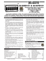
SOFTWARE LOGIC TREE
Zero
Apply Low Sig-
nal, enter de-
sired value, &
press Prog. but-
ton
Span
Apply High Sig-
nal, enter de-
sired value, &
press Prog. but-
ton
P
P
P
P
P
P
P
P
P
P
P
P
P
P
After power is supplied, the meter dis-
plays 8.8.8.8.8 for 3 seconds
Brightness
Display Adjustment 1 to 7 levels
Scale
Select desired Scale.
Example: For an input of 2 volts;
with SCAL of 1.5000, display = 30000
with SCAL of 1.0000, display = 20000
with SCAL of .50000, display = 10000
Address
Communication Option/Buss
address/Identification. Select from 0 to 255.
Baud Rate
Select from 200; 300; 600; 1200; 2400;
4800; 9600 or 19,2000 Baud
Code 1
Annunciator Status/ DP Position/Display
Rounding (Refer to pg. 4 Code Definitions)
Code 2
Display Flashing/Peak-Valley/Relay
Activation/Special Relay Function
(Refer to page 4, Code Definitions)
Code 3
Input-Auto Tare- Auto Cal/Analog
Output/Averaging (Refer to pg. 4 Code
Definitions)
Code 4
Conversion Rate/Input-Linearization/Input
Selection (Refer to pg. 4 Code Definitions)
hCA--- = Hardware Calibration
By selecting desired display values
and pressing Prog. while applying a
low and then a high input signal, the
meter will automatically calculate and
store the requisite offset and scaling
factors in PCA_.
This display indicates
the Span selected for
the input signal being
applied exceeds the
computational range of
the meter. The hCA—
mode may then be
reentered from the be-
ginning and a different
signal level applied or
span selected.
Offset
Select desired Offset Value.
(Note: Autotare function is also available.
See page 8.)
PCA_ = Program Calibration
Stores factors automatically derived from
hCA—or a user calculated offset value
and scaling factor can be directly entered
and stored.
Lockout
If LoC appears, Program Lockout Switch
is on. By pressing Prog, program parame-
ters may be viewed but can not be changed.
To exit program at any
stage, press Prog. button
and Up Arrow button si-
multaneously.
Note: If no buttons are
pressed for 12 to 30 sec-
onds, the programming
mode will time-out and
be exited automatically.
Any new display value
entered prior to pressing
Prog. will not be stored.
NOTE: All values shown below are standard factory default settings

Texmate, Inc. Tel. (760) 598-9899Page 4 3/31/00 DI-45U Data Sheet (DI2)
0 Thermocouple type R
1 Thermocouple type J
2 Thermocouple type T
3 Thermocouple type K
4 Resistance 2 or 4 wire
5 RTD Pt 100 2 or 4 wire
6 Resistance 3 wire
7 RTD Pt 100 3 wire
Blank
Conversion Rate 16/sec
1 Counter or frequency
2 Conversion rate 3/sec
3 Period measurement
When XXX0X, XXX2X,
or XXX4X, then:
When XXX1X or
XXX3X, then:
0 Voltage, Current, or Frequency
1 Temperature or Resistance
2 Inverse Voltage, Current or
Frequency
3 Inverse Temperature or Resis-
tance
4 Counter
5 Display Linearized Input Signal
6 Program Linearizaiton Points
7 Remote display via serial
communications
ANALOG OUTPUT
0 Remote control of Analog Output
1 Analog Output Display Data
2 Analog Output-Range Set
3 Analog Output-Calibrate
4 Analog Output-Raw Data
5 Not Used
6 Not Used
7 Not Used
AVERAGING
0 None
1 Over 2 samples
2 Over 4 samples
3 Over 8 samples
4 Over 16 samples
5 Over 32 samples
6 Over 64 samples
7 Smart filtering
Blank
Direct display of input
1 Cosine of input
2 Front panel auto-calibration
3 Front panel auto-tare
SPECIAL RELAY FUNCTION
0 None
1 Hysteresis in Counts
2 Time Delay in Seconds
3 Latching
4 Hysteresis in counts with Latching
5 Time Delay in seconds with Latching
6 Not used
7 Not used
0 No relays
1 Display VALLEY reading
2 Display PEAK reading
3 Not used
4 HiL1/HiL2 ON below setpoint
LoL1/LoL2 ON below setpoint
5 HiL1/HiL2 ON below setpoint
LoL1/LoL2 ON above setpoint
6 HiL1/HiL2 ON above setpoint
LoL1/LoL2 ON below setpoint
7 HiL1/HiL2 ON above setpoint
LoL1/LoL2 ON above setpoint
DISPLAY FLASHING
Blank
None
1 For LoL1, LoL2 violation
2 For HIL1, HIL2 violation
3 For any alarm violations
PEAK/VALLEY OR RELAY ACTIVATION
DISPLAY ROUNDING
0 None
1 By 2's
2 By 5's
3 By 10's
4 LSD dummy zero (MSD MAX 9)
5 By 20's (MSD MAX 9)
6 By 50's (MSD MAX 9)
7 By 100's (MSD MAX 9)
FRONT PANEL ANNUNCIATORS
Blank
Always OFF
1 ON when alarms OFF
2 ON when alarms ON
3 Indicate TREND
DECIMAL POINT PLACEMENT
0 None
1 None
2 Rear DP Select
X•XXXX/XX•XXX/XXX•XX/XXXX•X
3 Rear DP Select
XX•XXX/XXX•XX/XXXX•X/XXXX
4 X•XXXX
5 XX•XXX
6 XXX•XX
7 XXXX•X
PROGRAMMING CODE DEFINITIONS
0 Single Input Voltage, Current
1 Remote HIL1 or 2KHz
2 Dual Channel V1
3 Dual Channel V2 or 20KHz
4 Dual Channel V1 - V2
5 Dual Channel
(V1 x 20000)/V2 or 200KHz
6 Dual Channel V1 + V2
7 Dual Channel
(V1 x V2)/10000
NOTE: Standard factory default settings are shown in bold.

Texmate, Inc. Tel. (760) 598-98993/31/00 DI-45U Data Sheet (DI2) Page 5
VIEWING, VERIFYING AND ADJUSTING
SETPOINTS AND PEAK/VALLEY READINGS
STEP A Press “Prog”and “”simultaneously
DI-45U Displays toggle of [LoL1] and [XXXXX]
(-18000 is the default value)
STEP B Using the and , adjust display to
the desired value for LoL1 setpoint.
Press “Prog”.
DI-45U Displays toggle of [hiL1] and [XXXXX]
(18000 is the default value)
STEP C Using the and , adjust display to
the desired value for hiL1 setpoint.
Press “Prog”.
DI-45U Displays toggle of [LoL2] and [XXXXX]
(-5000 is the default value)
STEP D Using the and , adjust display to
the desired value for the LoL2 setpoint.
Press “Prog”.
DI-45U Displays toggle of [hiL2] and [XXXXX]
(5000 is the default value)
STEP E Using the and , adjust display to
the desired value for hiL2 setpoint.
Press “Prog”.
DI-45U Displays Operational Display
P
P
P
P
P
P
To exit program
at any stage
press Program
button and Down
Arrow button
EXPLANATION
TO SET AND ADJUST SETPOINT VALUES
P
P
PP
P
P
TO VIEW AND VERIFY SETPOINTS AND PEAK/VALLEY READINGS
To verify the SETPOINTS and PEAK/VALLEY
readings while under normal operation:
1. To verify the hiL1, press and release the “”.
2. To verify the hiL2, press and release the “”.
3. To verify the PEAK, press and release the “”.
4. To verify the LoL1, press and release the “”.
5. To verify the LoL2, press and release the “”.
6.
To verify the VALLEY, press and release the “”.
NOTE: If the DI-45U is ordered without setpoints,
LoL1 and hiL1 will appear with default values, but
will be inactive. If the DI-45U is ordered with two
setpoints, LoL2 and hiL2 will appear with default
values, but will be inactive. PEAK/VALLEY read-
ings are present with all versions.
EXPLANATION

Texmate, Inc. Tel. (760) 598-9899Page 6 3/31/00 DI-45U Data Sheet (DI2)
SET AND ADJUST HYSTERESIS
AND HYSTERESIS WITH LATCHING
P
P
P
P
P
P
P
P
TIME DELAY
SET AND ADJUST TIME DELAY
AND TIME DELAY WITH LATCHING
TIME DELAY WITH LATCHING
P
P
P
P
P
P
P
P
HYSTERESIS WITH LATCHING
HYSTERESIS
Change existing number in Digit 3 to a 1 for
Hysteresis or to a 4 for Hysteresis with Latching
Start at Code 2 (see pages 4 and 5)
Enter the desired number of counts (up to 127
counts for Hysteresis.)
Press Prog. button to move through Code 3
Press Prog. button to move through Code 4
and press Prog. again to return to operational
display.
Change existing number in Digit 3 to a 2 for
Time Delay or to a 5 for Time Delay with
Latching
Start at Code 2 (see pages 4 and 5)
Enter the desired number of counts (up to 127
counts for Time Delay.)
Press Prog. button to move through Code 3
Press Prog. button to move through Code 4 and
press Prog. again to return to operational display.

Texmate, Inc. Tel. (760) 598-98993/31/00 DI-45U Data Sheet (DI2) Page 7
P
P
P
P
P
P
P
P
STEP A Starting at Code 3 (see pages 4 and 5), set 2nd digit to a [x2x] by
pressing the up arrow (Setting of analog output range)
Press “Prog”.
DI-45U displays toggle of [ZEro] and [0]
STEP B Using the and , adjust display to the desired reading for a
zero output.
Press “Prog”.
DI-45U displays toggle of [F. S.] and [10000]
STEP C Using the and , adjust display to the desired reading for a
Full Scale output.
Press “Prog”.
DI-45U Displays toggle of [Cod3] and [x2x]
STEP D Connect a multimeter to the analog output pins 16 and 17. Adjust
Code 3 Digit 2 to a [x3x] (Calibrating of the analog output)
Press “Prog”.
DI-45U Displays toggle of [CAL_L] and a number. The exact number
displayed is irrelevant, as it is proportional to the internal offsets.
STEP E Using the and , adjust the analog output, as measured by
the multimeter to read exactly 0V or 0mA (depending on whether
the volt or current option has been selected on the output board)
Press “Prog”.
DI-45U Displays toggle of [CAL_h] and a number. The exact number
displayed is irrelevant, as it is proportional to the internal gain.
STEP F Using the and , adjust the analog output, as measured by
the multimeter to read exactly 10 V or 20 mA (depending on
whether the voltage or current option has been selected on the
output board)
Press “Prog”.
DI-45U Displays toggle of [Cod3] and [X3X]
STEP G Adjust Code 3 Digit 2 to a [x1x].
Press “Prog”button to move to Code 4, then press Prog. button
once again to return to operational display.
Procedure for Setting Up & Calibrating Analog Output
SET UP AND CALIBRATION OF ANALOG OUTPUT

Texmate, Inc. Tel. (760) 598-9899Page 8 3/31/00 DI-45U Data Sheet (DI2)
P
10 POINT LINEARIZATION
Prior to the actual programming, Texmate recommends that the
user define the 10 linearization points.To program the DI-45U to
linearize a signal, the procedure is as follows:
Step 1. Press “Prog”and simultaneously.
DI-45U Displays toggle of [PCA_] and [HCA _]
Note [HCA ] = Hardware Calibration. An external cali
bration device is required.
Hardware Calibration Procedure.
Step 2. Press . This is [HCA ].
DI-45U Displays toggle of [ZEro] and [0]. If the
number displayed is not 0, use and to
make display read 0.
Step 3. Apply to the Input Terminals, the minimum
value of the Input signal . Press“Prog.
DI-45U Displays toggle of [SPAn] and [10000] If
the number displayed is not 10000, use or
to make display read 10000.
Step 4. Apply to the Input Terminals, the maximum val-
ue of the Input signal. Press“Prog”.
DI-45U Displays [10000]
Step 5 Set Code 4 Digit 2 to a [x6x]. Press “Prog”
DI-45U Displays toggle of [P 00] and [0]
Step 6 Using the and , adjust display to the
desired reading when the minimum input is
applied to the DI-45U. Press “Prog”.
DI-45U Displays toggle of [P 10] and [1000]
Step 7 Using the and , adjust display to the
desired reading when 10% of the input is
applied to the DI-45U. Press “Prog”.
DI-45U Displays toggle of [P 20] and [2000]
Step 8 Using the and , adjust display to the
desired reading when 20% of the input
is applied to the DI-45U. Press “Prog”.
DI-45U Displays toggle of [P 30] and [3000]
Step 9 Using the and , adjust display to the
desired reading when 30% of the input is
applied to the DI-45U. Press “Prog”.
DI-45U Displays toggle of [P 40] and [4000]
Step 10 Using the and , adjust display to the de
sired reading when 40% of the input is
applied to the DI-45U. Press “Prog”.
DI-45U Displays toggle of [P 50] and [5000]
Step 11 Using the and , adjust display to the
desired reading when 50% of the input is
applied to the DI-45U. Press “Prog”.
DI-45U Displays toggle of [P 60] and [6000]
Step 12 Using the and , adjust display to the
desired reading when 60% of the input is
applied to the DI-45U. Press “Prog”.
DI-45U Displays toggle of [P 70] and [7000]
Step 13 Using the and , adjust display to the
desired reading when 70% of the input is
applied to the DI-45U. Press “Prog”.
DI-45U Displays toggle of [P 80] and [8000]
Step 14 Using the and , adjust display to the
desired reading when 80% of the input is
applied to the DI-45U. Press “Prog”.
DI-45U Displays toggle of [P 90] and [9000]ˇ
Step 15 Using the and , adjust display to the
desired reading when 90% of the input is
applied to the DI-45U. Press “Prog”.
DI-45U Displays toggle of [P100] and [10000]
Step 16 Using the and , adjust display to the
desired reading when the maximum input is
applied to the DI-45U. Press “Prog”.
DI-45U Displays toggle of [cod4] and [x6x]
Adjust Code 4 Digit 2 to a [x5x]. Press “Prog”.
until the DI-45U returns to the operational display.
TARE FUNCTION
STEP A Enter into the [PCA_] Program Mode by pressing “Prog”and
the “”simultaneously. DI-45U Displays toggle of [HCA ] and
[PCA_]
STEP B Press the .You are now in the [PCA_] Programming Mode.
STEP C Continue to press the “Prog”button until [cod3] appears.
STEP D Using the or , adjust the first digit to a [3xx].
STEP E Press “Prog”twice to return to the Operational Display
DI-45U Displays [INPUT]
A decimal point to the extreme right of the display will be illuminated when
the “Prog”is pressed. This is the indication that the Tare Function is en-
abled. The “Prog”is now the Tare button. Whenever the “Prog”is de-
pressed, the DI-45U will make the current display zero.
To reset the Tare Function, press the and simultaneously. The Tare
Function will be disabled and the display will return to normal.

Texmate, Inc. Tel. (760) 598-98993/31/00 DI-45U Data Sheet (DI2) Page 9
METERBOSS
Optional Multiple Meter Software
MeterBOSS gathers data from Texmate panel meters that have
serial ports and incorporates their readings into display, alarm,
logging and Logic Sequencer functions. MeterBOSS is a full-
featured, user-friendly software program for your IBM personal
computer (PC), PC compatible or laptop. No computer plug-in
cards are required, so MeterBOSS is ideal for laptops.
MeterBOSS is designed to be used without a reference manual.
Powerful automatic Hypertext help messages guide you through
MeterBOSS' simple straight forward operation. As new meters
are designed by Texmate, MeterBOSS' scrolling screens and
pop-up data windows will allow additions to be incorporated with-
out modifying MeterBOSS' familiar display format.
Applications
• Experimental data taking (laboratory)
• Prototype (test rigs)
• Quality checking (test stands)
• Product performance documentation (logging)
• Statistical quality control (data acquisition)
• Regulatory compliance (data acquisition and logging)
• Apparatus Sequencing (test stands)
• Monitoring remote meters (remote displays)
MeterBOSS Capabilities:
Display 1, 4, 9, or 16 instruments per screen as digital meters
Display 4, 9, or 16 instruments per screen as bargraphs
Set multiple alarms for each meter which will appear as flags on
the meter face or bargraph and/or operate input/output devices
User composed messages appear on screen when the asso-
ciated alarm is tripped
Display total number of alarms presently tripped
All alarm messages presently active are viewable on a single
screen
User selectable data logging at specific intervals, on alarm
tripp or manually on mouse click
Graphical display of data being logged or play back of previ-
ously logged data
Extensive Hypertext help messages virtually eliminates the
need for a manual
Setup by either keyboard or mouse (mouse highly recom-
mended)
All instruments and input/output devices presently supported
by MeterBOSS are selectable by mouse click from a scrolling list
All configured instrument options explained on and selected
from a specially designed instrument setup screen
Texmate instruments with RS-232 interface supported di
rectly (RS-422 and RS485 supported through adapters)
Concurrently operates instruments and I/O devices having
mixed baud rates and communication protocols
Communication integrity monitored and faults logged to a file
for analysis
Automatic communication port configuring, including location
and avoiding the mouse port
Any MeterBOSS configuration can be saved for future use
Automatically restarts itself from activity where program
stopped
Operates outputs from instrument values or internal Logic
Sequencer
Derived meter capability through mathematical relationships
to other meters
System cycle time continuously calculated and display
Logic Sequencer steps on time, instrument limits and logic or
all three
MeterBOSS Contents
1. MeterBOSS software on a 3 1/2" diskette in a sealed software
license envelope (5 1/4" if requested with order)
2. MeterBOSS instruction manual
3. User registration card
4. Documents explaining any User Referral Reward or Incentive
Programs that may be in effect at time of your purchase.
Hardware Requirements
MeterBOSS requires an IBM PC, XT or AT or 100% compatible
with 640 Kb minimum of RAM, hard disk, 3 1/2" (or 5 1/4" diskette
if requested at the time of order) drive and EGA/VGA video mon-
itor, and MS-DOS 3.0 higher. A mouse is highly recommended.
If more than a single instrument is to be operated by
MeterBOSS, your computer must be equipped with multiple
serial ports, or an external port multiplexer such as Texmate's
PortMUX. (Call for more information.)
MeterBOSS can operate most serial port (RS-232) equipped
instruments directly through your computer's serial port (RS-
422 and RS-485 supported through inexpensive industry stan-
dard port adapters.) A list of all meters supported by a specif-
ic version of MeterBOSS appears in a pop-up window on the
MeterBOSS Hardware Selection Screen. The ability to operate
additional instruments is being incorporated daily into the
MeterBOSS program. Contact Texmate for an up-to-date list of
instruments presently supported.
Estimated MeterBOSS Setup Time
1 Personalize original MeterBOSS
diskette and send in registration card 1 min
2 Install MeterBOSS on your computer 2 min
3 Pick the measurement instruments you
plan to use from MeterBOSS's menu 2 min
4 Select the measuring instrument
options you need to use for your job 8 min
5 Name the parameters and unit of
measure for the MeterBOSS screen
Display Meters 3 min
6 Relate (tie together) the Display
Meters with the measuring instruments
and set scale factors, tare values,
if needed 3 min.
7 Set alarm values (if needed) and
compose alarm messages to be
displayed with alarms are violated
(tripped) 1.5 min
Total average setup time 20.5 min

Texmate, Inc. Tel. (760) 598-9899Page 10 3/31/00 DI-45U Data Sheet (DI2)
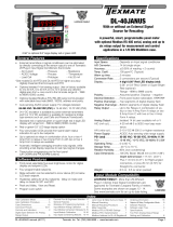
FUNCTIONAL DIAGRAM
CONNECTOR PINOUTS
The Texmate Model DI-45U TIGER CUB comes standard with
screw terminal block connections.
PIN DESCRIPTIONS
Pins 1 to 6 - Input Module. See the individual data sheet of the
input module selected for detailed information these pins or
pages 13-15 of this document. Usually Pin 1 is the Signal Input
High pin and Pin 3 is the Signal Input Low pin.
Pin 8 - Program Lock. By connecting this pin to the Common
Pin 11, the set up program is locked out. The programmed
meter parameters may be viewed but not changed, when the
meter is in the "locked out" mode.
Pin 9 - Hold Reading.
When this pin is connected to the
Common Pin 11, the reading displayed will be frozen. A/D conver-
sions will continue however, and as soon as Pin 9 is disconnected
from Pin 11 the updated reading will be instantly displayed.
Pin 10 - Display Test. When this pin is momentarily connected
to the Common Pin 11, all segments of the display light up and
five 8's are displayed for 3 seconds. This detects any missing
segments in the display. The microprocessor is also reset dur-
ing the 3 seconds.
Pin 11 - Common. To activate, Hold, Test, Lockout or Reset, the
respective pins have to be connected to this Common Pin.
Pin 14 & 15 - AC Power Input. These pins are the power input
pins of the meter. The standard DI-45U TIGER CUB is precon-
figured for 100/120VAC for meters sold in North America. To
reconfigure for 200/240VAC operation, remove the meter from
the case and pull out the AC Power Voltage Selector located
directly behind the transformer on the printed circuit board. Turn
the AC Power Voltage Selector around and reinsert it into the
socket so that "200/240VAC" is visable. See the Component
Layout on page 10.
Chassis Ground Tab - This grounding tab is supplied for chas-
sis grounding.
POWER SUPPLY
The standard power supply for the DI-45U TIGER CUB is 100
to 120VAC or 200 to 240VAC, user selectable. See the Pin Out
Descriptions for Pins 14 and 15 for more details.
GND
30 23
29 24
25
27 26
28 17 16
1920 18
SERIAL OUTPUT
OPTIONAL SETPOINT RELAYS 21
Lo1 Lo2 Hi1 Hi2
+
Logic
ANALOG OUT
(Non-Isolated)
(Non-Isolated)
200-240 VAC
100-120 VAC
14 15
AC
POWER
for display range
0 to 10 VDC
0 to 20 mA
4 to 20 mA
HOLD
TEST
LOCK
COMMON
11
910
8
456
23
1
INPUT PINS (DEPENDS
ON SPECIFIC
MODULE SELECTED)
47K
47K
COM NO
COM NO
COM
NC
1
2
3
4
5
6
7
+5V DC
-5V DC
I/O 1
I/O 2
INPUT
MODULE
Input Module
+24V DC
8
9
10
11
14
15
Display Test
Micro Reset
Common
+5V DC
- 5V DC
+24VDC
GND
MAIN BOARD
DISPLAY BOARD
GND
MicroProcessor
8.8.8.8.8
OPTIONAL OUTPUT BOARD
Form C
Logic Level TTL
Serial Output
Analog
Lo1
Lo2
See specific
Input Lo
Input Hi
or HOLD
1
2
3
4
5
6
Program and
Setpoint Lock
Switches
Hi1
Hi2
10A
Form C
10A
5A
Form A
5A
Form A
23
24
25
26
27
28
29
30
21
20
19
18
17
16
Output
Volts mA
0.01
GND
GROUND
RXD
TXD
+5V -5V
GND
NORMALLY
NORMALLY
NORMALLY
OPEN Lo1
CLOSED Lo1
COMMON Lo
OPEN Lo2
NORMALLY
NORMALLY
NORMALLY
OPEN Hi1
CLOSED Hi1
COMMON Hi
OPEN Hi2
_
ANALOG
OUTPUT
Program Lock
Reading Hold
There are Input Modules
for almost any input signal.
Input Pins vary for different
modules, so please
for connection Details
Data Sheets
A/D
Converter
Crowbar
Protection
Circuit for
Over
voltage
+24V
J1
J2
Internal Header Pins
and EEPROM
Prog
Alarm
Annunciators
Front Panel
Push Buttons
NO
NO
COM
NC
8
9
10
GND
REFERENCE HI
REFERENCE LO
L2 L1 H1 H2
+5VDC
AC POWER
SELECTOR
RECTIFIER &
REGULATOR

Texmate, Inc. Tel. (760) 598-98993/31/00 DI-45U Data Sheet (DI2) Page 11
Pin 1 - +5VDC @ 160mA Power. For Relay Driver Circuits
Pin 2 - Ground. For Relay Driver Circuits
Pin 3 - Reserved for future use
Pin 4 - To LoL1 Driver Circuit-Alarm Status
Pin 5 - Squarewave to Analog Output, Frequency to Voltage
Circuit
Pin 6 - Reserved for future use
Pin 7 - To HiL1 Driver Circuit-Alarm Status
Pin 8 - RXD (CMOS Logic Levels)
Pin 9 - TXD (CMOS Logic Levels)
Pin 10 - To HiL2 Driver Circuit-Alarm Status
Pin 11 - To LoL2 Driver Circuit-Alarm Status
Pin 12 - Ground. For Analog Output Circuit.
Pin 13 - +18VDC @ 30mA Power. For Analog Output Circuit.
MICRO
PIN 1 PIN 11 PIN 12
PIN 13
COMPONENT LAYOUT
DISPLAY BOARD TO
OPTIONAL OUTPUT MODULE
INTERCONNECTION
MAIN BOARD COMPONENT SIDE
DISPLAY BOARD PIN SIDE
Pins
1 3 5 7
Pin
24 68
9
10
Socket for Signal
Conditioning Board Main Board
MAIN BOARD TO
SIGNAL CONDITIONING MODULE
INTERCONNECTION
Pin 1 - A/D Converter Input Hi. Maximum ±2VDC.
Pin 2 - A/D Converter Input Lo. Maximum ±2VDC.
Pin 3 -
+5VDC @ 30mA. To power the input signa conditioner.
Pin 4 - -5VDC @ 30mA Power. To power the input signal
conditioner.
Pin 5 - +24VDC @ 25mA. If pad J is opened, Pin 5 will
become HOLD.
Pin 6 - Ground for Input Signal Conditioner
Pin 7 - Reference voltage positive (+)
Pin 8 - Reference voltage negative (-)
Pin 9 - Input/Output 1 to microprocessor
Pin 10 - Input/Output 2 to microprocessor
SIGNAL CONDITIONING
MODULE OPTIONS
A signal conditioning module is required to operate the DI-45U
meter. A separate ordering guide and an individual, specific
data sheet is available for each module. See pages 13-15 for
general information. Some of the input options include DC
Volts, DC millivolts, DC milliamps, AC Volts, AC millivolts, AC
milliamps, ACV Trms, AC mA Trms, Process input (with and
without excitation), Thermocouple, RTD, Strain gage, Pressure,
Resistance, Frequency, and others, some with dual inputs.
Contact factory for more information.

Texmate, Inc. Tel. (760) 598-9899Page 12 3/31/00 DI-45U Data Sheet (DI2)
OPTIONAL OUTPUT MODULE OUTPUT MODULE PINOUTS
RELAY OUTPUT PINOUTS
Choose up to four relays per module.
User software selectable NO/NC relay status.
LoL1/HiL1 are 10Amp/240VAC high insulation Form C relays.
LoL2/HiL2 are 5 Amp/240VAC high insulation Form A relays.
Pin 23 - Normally Open HIL2. 5A/240VAC Contact.
Pin 24 - Common HIL1 and HIL2
Pin 25 - Normally Closed HIL1. 10A/240VAC contact.
Pin 26 - Normally Open HIL1. 10A/240VAC contact.
Pin 27 - Normally Open LOL2. 5A/240VAC contact.
Pin 28 - Common LOL1 and LOL2
Pin 29 - Normally Closed LOL1. 10A/240VAC contact.
Pin 30 - Normally Open LOL1. 10A/240VAC contact.
Relay Output Outputs Available
One 10A/240VAC Form C
Two 10A/240VAC Form C
Two 10A Form C/One 5A Form A
Two 10A Form C/Two 5A Form A
30 23
29 24
25
27 26
28 17 16
1920 18
OPTIONAL SETPOINT RELAYS 21
+
ANALOG OUT
(Isolated)
SERIAL OUTPUT
RS232
RS485
(Isolated)
18 to 36 VAC
9 to 60 VDC
85 to 265 VAC
95 to 370 VDC
Lo1 Lo2 Hi1 Hi2
for display range
0 to 10V
0 to 20mA
4 to 20mA
GND
HOLD
TEST
LOCK
COMM
11
910
814 15
AC/DC
POWER
ANALOG OUTPUT PINOUTS
Pin 16 - Positive Analog Output
Pin 17 - Negative Analog Output
Analog Output Options Available
Non-Isolated Current output (0-20mA)
Non-Isolated Voltage output (0-10VDC)
User selectable 0-10VDC into 5KΩmaximum or 0-20mA DC into
500Ωmaximum. Desired scaling for 4-20mA, 1-5VDC, 0-1VDC.
Front panel programmable. Only one analog output per module.
Pin 18 - RXD.Received Serial Output
Pin 19 - TXD. Transmitted Serial Output
Pin 20 - +5VDC.
Pin 21 - Ground for Serial communication
Serial Communication Output Available
Logic level TTL Non-isolated Serial Output. To communicate
with PC’s, use the external Texmate logic to RS232 Isolated
Converter.
SERIAL COMMUNICATION PINOUTS
Choose only one type of serial communication per module.
Component Side
Output options include up to four heavy duty, high isolation 5 and
10 amp relays that can be programmed individually to operate in
any desired manner. An independently programmable analog
output is available that can be user configured for 4-20mA, 0-
20ma or 0 to 10VDC. The isolated serial output is available as
RS-232C or RS-485. All or any combination of these options may
be combined on one module. The above illustration shows a fully
loaded Output Module with RS-232C Serial Communication. If
any one of the output options is not included, the components
are simply not placed.
Main
Board
Rear View of
Display Board
Pins 1-11
Pins 1-10
Signal
Conditioning
Module
1 3 5 7 9
2 4 6 8 10
Pins 12 & 13
Optional
Output
Module
Socket Pins
In this view, the meter has been removed from the case. Visible
is the Signal Conditioning Module, the Optional Output Module
and the rear view of the Display Board.
EXPLODED VIEW OF METER
Analog Output
Relay
Output Serial
Communication
Socket
RJ-11
Socket
Pin 16
Pin 17
Pin 23
Pin 30
Pin 13 &
Pin 12
Socket
Pin 11
Pin 1

Texmate, Inc. Tel. (760) 598-98993/31/00 DI-45U Data Sheet (DI2) Page 13
SINGLE INPUT SIGNAL CONDITIONING MODULES
See individual module data sheets for more information. Order numbers for each module are the three letter codes shown in bold.
The DI-45U may be used in a wide variety of applications. The following circuits illustrate some of the possibilities and demonstrate
the exceptional versatility of DI-45U. Components called for in the applications which are not part of the standard meter may be sup-
plied by the user or in some cases purchased from Texmate. The circuit diagrams explain the basic pinout connections required for
each application. NOTE: Use of these application circuits is entirely at the risk and responsibility of the user and any user modifica-
tion of the meter may at the discretion of Texmate, void the warranty. (See rear page for user's responsibility and warranty details.)
TYPICAL APPLICATION CIRCUITS & CONNECTION INSTRUCTIONS
A06: AC Volts Trms High 200V/600V AC
600V
200V
A04 (1 A AC) or A05 (5 A AC): AC AMPS
Averaging 1 A AC or 5 A AC D01: DC Volts 2/20/200 V DC
Custom
200V
20V
2V
< Increase Decrease >
A09 (1 A AC) or A11 (5 A AC): AC AMPS
Trms 1 A AC or 5 A AC
A03: AC mA Averaging 2mA/20mA/200mA AC
2mA
20mA
200mA
A02: AC Volts Average Low 200mV/2V/20V AC
20V
2V
0.2V
A01: AC Volts Average High 200V/600V AC
LN
600V
200V
A08: AC mA Trms 2mA/20mA/200mA AC
2mA
20mA
200mA
A07: AC Volts Trms Low 200mV/2V/20V AC
200mV
2V
20V
200
100
50
20
D02:
DC Millivolts Universal Divider 20/50/100/200 mV

Texmate, Inc. Tel. (760) 598-9899Page 14 3/31/00 DI-45U Data Sheet (DI2)
TYPICAL SINGLE INPUT MODULES continued
–
0
+
D03: DC Milliamps Universal Divider 2/20/200 mA
Optional 0.2mA Range Available
2 mA
20 mA
200 mA
F01:
RPM-20 V AC, 5-30 V DC, 3 selectable ranges;
0-2 kHz, 0-20 kHz and 0-200 kHz
0-1V/4-50V
20mV-250V
NPN
PNP
FREQUENCY/RPM
D04: DC mAmps, 1 or 5 Amps DC Direct
(Please specify when ordering)
F02:
Line Frequency 50 to 500 V AC,
3 selectable
ranges;
0-2 kHz, 0-20 kHz and 0-200 kHz
FTR
DC
D05: DC-VOLTS, 2/20/200/600 V DC range and
24 V DC excitation
F03:
Frequency 1 to 50 V AC 5-30 V DC,
3 selectable
ranges;
0-2 kHz, 0-20 kHz and 0-200 kHz
FTR
DC
D06: DC-VOLTS, 2/20/200/600 V DC range with
External Decimal Point selection
P01: Process 4-20 mA = 0–10000
ZERO COARSE incr.
SPAN COARSE incr.
Common
D07: DC-MILLIAMP, 2/20/200 mAmps DC with
offset adjustment
2mA
20mA
200mA
P02:
Process 4-20 mA = 0–10000 with 24 V DC Excitation
ZERO COARSE incr.
SPAN COARSE incr.
Common
PIN 2
With external excitation,
use Pin 2 instead of Pin 3
P03: Process 1-5 V DC = 0–10000 with offset
adjustment and 24 V DC Excitation
< Increase Decrease > + 0 –
Offset
Custom
200V
20V
2V
PT1:
Prototype bare board for customer design and build

Texmate, Inc. Tel. (760) 598-98993/31/00 DI-45U Data Sheet (DI2) Page 15
TYPICAL SINGLE INPUT MODULES continued
S03: Pressure with Auto-cal 5/10 VDC Excitation,
2 mV to 20 mV/V - 4 wire
2
20
mV/V
10V
5V
Cal
4W
6W
S04:
Pressure, without excitation, For use with multiple
Pressure Sensor 4-wire or 6-wire, 2 mV/V–20 mV/V
2
20
mV/V
5V
10V 4W
6W
R01: Resistance (2-,3-,4- wire) 200 Ω/2K Ω/20K Ω
20K 2K 200Ω
T01:
Thermocouple Universal, J, K, R, S or T. 32 pt.
Linearization. NOTE: For any other TC, Contact TEXMATE
R/S
K/T
J
S01: Strain Gage with 5/10 V DC Excitation,
2 mV/V to 20 mV/V, 4 or 6 wire
2
20
mV/V
10V
5V
Cal
4W
6W
T02:
Pt. 100Ω RTD–(2-,3-,4- wire) 0 to 200.0˚C (32.0 to
392.0˚F) -200 to 800˚C (-328.0 to +1472.0˚F). a curve 385
NOTE: For Pt 1000 Ω, Contact TEXMATE
S02: Pressure with 5/10 V DC Excitation, 2 mV to
20 mV/V, 4 or 6 wire
2
20
mV/V
10V
5V
Cal
4W
6W
T05: Cu 10 Ω Copper (2-,3-,4- wire) 0 to 200.0˚C
(32.0 to 392.0˚F) -200 to 800˚C (-328.0 to +1472.0˚F)
T12: Infrared Temperature Sensor Input using
32Pt. Linearization
R/S
K/T
J
W02: Watt Input 300 VAC/5 Amp AC 1Ph/2 Wr
W01: Watt Input 300 VAC/1 Amp AC 1Ph/2 Wr

Texmate, Inc. Tel. (760) 598-9899Page 16 3/31/00 DI-45U Data Sheet (DI2)
CALIBRATION
The DI-45U TIGER CUB is a precision digital panel instrument using
Dual Slope integration capable with 16 bit resolution employing 'intuitive
software' (available from the front panel or through the serial multiple
meter software interface) to select the input signal type and scaling. The
display averaging and rounding ensures stable displayed readings and
outputs. All signals may be scaled for desired engineering unit.
CALIBRATION: The DI-45U TIGER CUB meter is calibrated prior to
shipment, using equipment certified to NIST standards. Calibration con-
stants are stored in non-volatile memory in a EPROM. Recalibration for
units installed with a serial interface is completed using the application
software supplied with the meter. If the unit does not have a serial inter-
face, it must be returned to Texmate for recalibration.
CONNECTORS
The DI-45U TIGER CUB comes standard with plug-in screw terminal
blocks. To connect the instrument, make sure the screw terminal block is
securely attached to the pin socket on the printed circuit board. For each
input required, loosen the screw above the designated input (see specif-
ic module sheets or meter label for input diagrams), place input wire into
the square opening below screw, then retighten screw.
2-pin connector
4-pin connector
Connector attaches to meter here
Screw terminals for all connections
Texmate has facilities in Japan, New Zealand, Taiwan, and Thailand. We also
have authorized distributors throughout the USA and in 28 other countries.
Local Distributor Address
995 Park Center Drive • Vista, CA 92083-8397
Tel: (760) 598-9899 • Fax: (760) 598-9828
URL: http://www.texmate.com
WARRANTY
Texmate warrants that its products are free from defects in material and workmanship under nor-
mal use and service for a period of one year from date of shipment. Texmate’s obligations under this
warranty are limited to replacement or repair, at its option, at its factory, of any of the products which
shall, within the applicable period after shipment, be returned to Texmate’s facility, transportation
charges pre-paid, and which are, after examination, disclosed to the satisfaction of Texmate to be thus
defective. The warranty shall not apply to any equipment which shall have been repaired or altered,
except by Texmate, or which shall have been subjected to misuse, negligence, or accident. In no case
shall Texmate’s liability exceed the original purchase price. The aforementioned provisions do not
extend the original warranty period of any product which has been either repaired or replaced by
Texmate.
USER’S RESPONSIBILITY
We are pleased to offer suggestions on the use of our various products either by way of printed
matter or through direct contact with our sales/application engineering staff. However, since we have
no control over the use of our products once they are shipped, NO WARRANTY WHETHER OF MER-
CHANTABILITY, FITNESS FOR PURPOSE, OR OTHERWISE is made beyond the repair, replace-
ment, or refund of purchase price at the sole discretion of Texmate. Users shall determine the suit-
ability of the product for the intended application before using, and the users assume all risk and lia-
bility whatsoever in connection therewith, regardless of any of our suggestions or statements as to
application or construction. In no event shall Texmate’s liability, in law or otherwise, be in excess of
the purchase price of the product.
Texmate cannot assume responsibility for any circuitry described. No circuit patent licenses are implied.
Texmate reserves the right to change circuitry, specifications, and prices without notice at any time.
CASE DIMENSIONS
TOP VIEW
87 mm
(3.425")
96 mm
(3.78")
91.6 mm
(3.6") (mosaic fitting)
96 mm
(
3.78"
)
48 mm
(1.89")
41 mm
(1.61")
3.4 mm
(0.13") (typ.)
FRONT VIEW
117 mm
(4.61")
SIDE VIEW
5.7 mm (0.22")
PANEL CUTOUT
45 mm
(1.77")
92 mm
(3.62")
44 mm
(1.73")
Front panel cutout 3.63" W x 1.78" H (92 x 45 mm)
Bezel size (W x H x D) 3.79" W x 1.9" H x 0.23"D (96 x 48 x 5.7 mm), black
TYPICAL DUAL INPUT MODULES
DD3: Dual Input mA DC/mA DC W/Excitation
+ 24V Excitation
DP1: Dual Process 4-20 mA/4-20 mA
DD1: Dual Input Volts DC/Volts DC
DD2: Dual Input mV DC/mV DC
/