Page is loading ...

1 / 22 DELTA ELEKTRONIKA B.V. rev. Jan. 2022
DELTA
ELEKTRONIKA B.V.
Vissersdijk 4, 4301 ND www.DeltaPowerSupplies.com
DC POWER SUPPLIES Zierikzee, the Netherlands Tel. +31 111 413656
SM800-series
SM7.5-80
SM18-50
SM70-AR-24
SM400-AR-4
PRODUCT MANUAL
Contents:
1 – Safety Instructions
2 – Sicherheitshinweise
3 – General
4 – Installation
5 – Trouble Shooting
6 – Maintenance & Calibration
7 – EU Declaration of Conformity
8 – UK Declaration of Conformity
Product Manuals and Driver & Example Software
For several Applications, build-in Options and Interfaces there are Application
Notes, separate Product Manuals and Driver & Example Software available on
our website. See PRODUCTS\SM800\DOWNLOADS.

SAFETY INSTRUCTIONS SM800
2 / 22 DELTA ELEKTRONIKA B.V. rev. Jan. 2022
Warning! When the 'plus' DC power terminal can exceed 60VDC in respect to the 'minus' DC power terminal,
additional external measures must be taken to ensure safety isolation of the DC power terminals and sense
connections.
Warning! When the 'minus' DC power terminal of the unit can exceed 60VDC / 42.4Vpk in respect to ground,
additional external measures must be taken to ensure safety insulation of the following:
- DC power terminals and sense connections.
- programming/monitor/status-signals, Interlock, Master/Slave connections, ACF/DCF-relay.
- interfaces with functional insulation, non-insulated interfaces.
.
1
SAFETY INSTRUCTIONS – SM800-series
1.1
Caution
The following safety precautions must be observed during all phases of operation, service and repair of this equipment.
Failure to comply with the safety precautions or warnings in this document violates safety standards of design,
manufacture and intended use of this equipment and may impair the built-in protections. Delta Elektronika shall not be
liable for user’s failure to comply with these requirements.
1.2
Installation Category
The Delta Elektronika power supplies have been evaluated to installation category II (Over voltage category II).
1.3
Grounding of Mains Terminals (AC Power Terminals)
This product is a safety Class 1 unit. To minimize shock hazard, the unit must be connected to the AC Power Supply
mains through a three conductor power cable for a single phase unit, with the ground wire firmly connected to an
electrical ground (safety ground) at the power outlet.
For units designed to be hard-wired to the mains supply, the protective earth terminal must be connected to the safety
electrical ground before another connection is made. Any interruption of the protective ground conductor, or
disconnection of the protective earth terminal will cause a potential shock hazard that might cause personal injury.
1.4
Grounding of DC Power Terminals
If the DC power terminal of a unit is specified to sink or source to a maximum of 60VDC, and either the 'minus' or 'plus'
DC power terminal is grounded, the voltage on the following connections can be considered safe:
- DC power terminals and sense connections.
- programming/monitor/status-signals, Interlock, Master/Slave connections, ACF/DCF-relay.
- all Delta Elektronika interfaces.
Caution 1: If a low voltage unit has both DC power terminals floating, or if the DC terminals are in series with an external
high AC or DC voltage, the 'minus' DC power terminal can exceed the safe value in respect to ground as specified in the
above warning!
Caution 2: Although a high voltage unit is set to a safe voltage below 60VDC, for safety it must always be considered as
a high voltage unit! Wrong operation, a programming error or an external defect can result in an unsafe high DC output
voltage.
Caution 3: when programming a high voltage unit directly via a PC or a network connection, either ground the 'minus'
DC power terminal or use a safety insulated interface!
For more information regards Grounding & Safety, see online application note "Safe operation of a power supply".
1.5
Danger of electrical shock
Touching the contacts of the mains plug or wires directly after disconnecting from the mains, can cause an electrical
shock. And there can still be a dangerous voltage between one of the DC power terminals and the PE because of
charged X-capacitors. This can also happen when the DC power output is switched off, but the unit is still switched on!
Therefore never touch PE and one of the DC power terminals at the same time.
1.6
Connection to mains supply
Either connect to the mains supply permanently or via an industrial type plug, complying with IEC 60309.
"Permanently connected equipment" or "Pluggable equipment type B".
1.7
Fuses
Fuses to be changed by authorized Delta Elektronika service personnel only, for continued protection against risk of fire.
1.8
AC Input Ratings
Do not use an AC Supply which exceeds the AC input voltage and frequency rating of this unit. The AC input voltage and
frequency rating of the Delta Elektronika power supply series are stated in the accompanying datasheet.
1.9
Live Circuits
Operating personnel should not remove the unit covers. No internal adjustment or component replacement is allowed by
non Delta Elektronika qualified personnel. Never replace components with the power cable connected. To avoid injuries,
always disconnect power, remove external voltage sources and discharge circuits before touching components.
1.10
Parts Substitutions & Modifications
Parts substitutions and modifications are allowed by authorized Delta Elektronika service personnel only. For repairs the
unit must be returned to a Delta Elektronika service facility.

SAFETY INSTRUCTIONS SM800
3 / 22 DELTA ELEKTRONIKA B.V. rev. Jan. 2022
This marking shown on the product, its packing or its literature indicates that it should not be disposed with
other wastes at the end of its working life, but should be collected separately to recycle it responsibly to
promote the sustainable reuse of material resources.
WEEE (Waste Electrical & Electronic Equipment)
1.17
Correct Disposal of this Product
Applicable in the European Union.
1.11
Removal of (safety) covers
Safety cover(s) are used to cover potentially hazardous voltages.
Observe the following when removing safety cover(s):
Switch off the unit and disconnect the unit from the AC mains supply and from the DC power application.
Wait for 5 minutes to allow internal capacitors to discharge, then unscrew and remove the cover(s).
Always place the cover(s) back before connecting the unit to the mains supply again.
1.12
Handling and mounting
Warning! Unit weight is 5.5kg! Take care when unpacking or moving unit:
Risk of crushing or clamping of limbs!
Risk of cutting: unit has sharp edges and corners!
Warning! No wall mounting or ceiling mounting allowed! Risk of crushing under unit.
Only mount unit horizontally, place on a stable surface or use rack mounting.
1.13
Rotating fan, thermal burn
Proper air flow is required for cooling of the unit. This enables operation at full power and a longer life time.
If the unit gets over heated, the power will shut down until unit has cooled down again.
Warning! Top cover and fan exhausts can get hot. Avoid touching these while operating the unit at high power!
Warning! Do not block fan openings, or air exhausts. Do not try to enter fan openings by any object to obstruct fan.
Long hair can get stuck in fan, wear a hairnet if you have long hair.
Warning! Do not (dis)connect cables to the DC power terminals while the unit is on. Sudden making or breaking of
high DC currents can cause large sparks, even at low voltages. Risk of thermal burn and fire!
1.14
Electro medical devices
Warning! High currents can run through the DC power terminals. These currents cause strong magnetic fields. Do
not come near if you have an electro medical device such as a pacemaker.
1.15
Environmental Conditions
The Delta Elektronika power supplies safety approval applies to the following operating conditions:
Usage : Indoor use only.
Warning! Not intended to be used in the presence of children or animals!
Ambient temperature : -20 to 50 °C.
Maximum relative humidity : 95%, non condensing, up to 40 °C, 75%, non condensing, up to 50 °C.
Altitude : Do not use above 2000 m sea level.
Warning! Electrical Creepage & Clearance not valid for higher altitudes!
Pollution degree : 2
1.16
Symbols & markings
Caution risk of electrical Shock.
Instruction manual symbol. The instrument will be marked with this symbol when it is
necessary fort he user to refer to the instruction manual.
Protective ground conductor terminal.
Off (supply).
On (supply).

SAFETY INSTRUCTIONS SM800
4 / 22 DELTA ELEKTRONIKA B.V. rev. Jan. 2022
2
SICHERHEITSHINWEISE – SM800-series
2.1
Vorsicht
Die folgenden Sicherheitsvorkehrungen müssen in allen Betriebs-, Service- und Reparaturphasen dieses Geräts befolgt
werden. Die Nichteinhaltung der Sicherheitsvorkehrungen oder Warnungen in diesem Dokument verstößt gegen die
Sicherheitsstandards im Hinblick auf Bauart, Produktion und vorgesehene Nutzung dieses Geräts und kann die
eingebauten Schutzvorrichtungen beschädigen. Delta Elektronika haftet nicht dafür, wenn der Nutzer diesen
Anforderungen nicht nachkommt.
2.2
Installationskategorie
Die Delta Elektronika Stromversorgungen wurden der Installationskategorie II (Überspannungskategorie II) zugeordnet.
2.3
Erdung der Netzanschlussklemmen (AC-Einspeiseklemmen)
Dieses Produkt ist ein Gerät der Sicherheitsklasse 1. Um die Gefahr eines elektrischen Schlags zu minimieren, muss das
Gerät mit einem Dreileiter-Stromkabel mit dem AC-Stromversorgungsnetz verbunden werden. Hierbei muss der
Schutzleiter fest mit einem elektrischen Erdungsanschluss (Schutzleiter) an der Stromquelle verbunden sein. Bei
Geräten, die fest mit dem Versorgungsnetz verdrahtet werden, muss die Schutzerdungsklemme mit dem
Sicherheitserdungsanschluss verbunden werden, bevor eine andere Verbindung hergestellt wird. Eine Unterbrechung
des Schutzleiters oder eine Trennung der Schutzerdungsklemme kann zu einem elektrischen Schlag führen, der zur
Verletzung von Personen führen kann.
2.4
Erdung der DC-Anschlussklemmen
Wenn die DC-Anschlussklemme eines Geräts dafür ausgelegt ist, maximal 60 VDC zu empfangen oder zu beziehen und
entweder die 'minus' oder 'plus' DC-Anschlussklemme geerdet ist, kann die Spannung als sicher angesehen werden für:
- DC-Anschlussklemmen und Sense-Anschlüsse.
- Programmierung-/Monitor-/Status-Signale, InterLock, Master/Slave Anschlüsse, ACF/DCF-Relais.
- Alle Delta Elektronika Schnittstellen.
Warnung! Wenn die 'plus' DC-Anschlussklemme im Verhältnis zur 'minus' DC-Anschlussklemme 60 VDC
überschreiten kann, müssen zusätzliche externe Maßnahmen ergriffen werden, um die Sicherheitsisolation der DC-
Anschlussklemmen und Sense-Verbindungen sicherzustellen.
Warnung! Wenn die 'minus' DC-Anschlussklemme im Verhältnis zur Erdung 60 VDC/42,4 Vpk überschreiten kann,
müssen zusätzliche externe Maßnahmen ergriffen werden, um die Sicherheitsisolation sicherzustellen für:
- DC-Anschlussklemmen und Sense-Anschlüsse.
- Programmierung/Monitor/Status-Signale, InterLock, Master/Slave Anschlüsse, ACF/DCF-Relais.
- Schnittstellen mit Funktionale Isolation, Schnittstellen ohne Sicherheitsisolation.
Vorsicht 1: Falls beide DC-Anschlussklemmen eines Niederspannungsgerätes potentialfrei sind oder falls die DC-
Klemmen in Reihe mit einer externen AC- oder DC-Hochspannung geschaltet sind, kann die 'minus' DC-
Anschlussklemme den sicheren Wert in Bezug auf die Erdung wie in der Warnung oben spezifiziert überschreiten.
Vorsicht 2: Obwohl ein Hochspannungsgerät mit einer sicheren Spannung unter 60 VDC betrieben wird, muss es zur
Sicherheit immer als Hochspannungsgerät angesehen werden! Falsche Bedienung, ein Programmierfehler oder ein
externer Fehler können zu einer unsicheren, hohen DC-Ausgangsspannung führen.
Vorsicht 3: Wenn ein Hochspannungsgerät direkt über ein PC oder Netzwerk Verbindung programmiert wird, muss
oder die 'minus' DC-Anschlussklemme mit PE verbunden wurden, oder muss ein Schnittstelle mit Sicherheitsisolation
gebraucht wurden! Für weitere Informationen und Schaltpläne hinsichtlich Erdung und Sicherheit, siehe den online
Applikationshinweis 'Safe operation of a power supply'.
2.5
Gefahr eines elektrischen Schlags
Das Berühren der Kontakte des Netzsteckers oder der Kabel direkt nach der Trennung vom Netz kann zu einem
elektrischen Schlag führen. Und aufgrund von geladenen X-Kondensatoren, kann gefährliches Potential zwischen 'plus'
oder ‘minus’ DC-Anschlussklemme und PE bestehen oder entstehen. Auch wenn die DC-Anschlussklemmen
ausgeschaltet sind, aber das Gerät noch eingeschaltet ist. Daher niemals gleichzeitig PE und einen der DC-
Anschlussklemmen berühren mit bloßen Händen.
2.6
Verbindung mit dem Versorgungsnetz
Entweder permanent mit dem Versorgungsnetz verbinden oder via einer Industriesteckverbindung entsprechend IEC
60309. „Permanent verbundene Ausrüstung“ oder „Steckbare Ausrüstung Typ B“.
2.7
Sicherungen
Sicherungen dürfen ausschließlich von autorisiertem Delta Elektronika-Service-Personal ausgetauscht werden, um
Brandgefahr dauerhaft auszuschließen.
2.8
AC-Eingangsleistung
Verwenden Sie keine AC-Versorgung, welche die AC-Eingangsspannung und Frequenzleistung dieses Geräts
überschreitet. Die AC-Eingangsspannung und Frequenzleistung der Delta Elektronika-Stromversorgungsserie sind im
beiliegenden Datenblatt angegeben.
2.9
Spannungsführenden Stromkreise
Bedienungspersonal darf die Geräteabdeckungen nicht entfernen. Interne Einstellungen oder Bauteileaustausche sind
ausschließlich qualifiziertem Personal von Delta Elektronika gestattet. Bauteile nie bei eingestecktem Stromkabel
austauschen. Um Verletzungen zu vermeiden, vor dem Berühren von Bauteilen immer den Strom trennen, externe
Spannungsquellen entfernen und Stromkreise entladen.

SAFETY INSTRUCTIONS SM800
5 / 22 DELTA ELEKTRONIKA B.V. rev. Jan. 2022
2.10
Teileaustausch & Modifikationen
Teileaustausch und Modifikationen sind ausschließlich autorisiertem Delta Elektronika-Service-Personal gestattet.
Reparaturen am Gerät dürfen nur durch eine Delta Elektronika-Serviceeinrichtung durchgeführt werden.
2.11
Entfernung von (Sicherheits-) Abdeckungen
Sicherheitsabdeckung(en) werden verwendet, um potenziell gefährliche Spannungen abzudecken. Beachten Sie
Folgendes, wenn Sie die Sicherheitsabdeckung(en) entfernen:
Gerät ausschalten, Gerät von dem AC-Versorgungsnetz und DC-Anwendung trennen.
Warten Sie 5 Minuten um interne Kondensatoren zu entladen. Abschrauben und entfernen von Abdeckung(en).
Bevor Sie das Gerät wieder mit dem Versorgungsnetz verbinden, montieren Sie vorher jedes Mal die Abdeckung(en).
2.12
Handhabung und Montage
Warnung! Einheit Gewicht ist 5.5kg! Beim Auspacken oder Umziehen vorsichtshalber: Gefahr der Zerkleinerung der
Gliedmaßen unter Einheit. Risiko des Schneidens: Einheit hat scharfe Kanten und Ecken!
Warnung! Keine Wandmontage oder Deckenmontage erlaubt! Gefahr der Zerkleinerung unter Einheit. Nur Einheit
horizontal montieren, auf eine stabile Oberfläche stellen oder Rack-Montage verwenden.
2.13
Rotierender Lüfter, thermischer Verbrennung
Für die Kühlung des Geräts ist ein richtiger Luftstrom erforderlich. Dies ermöglicht den Betrieb bei voller Leistung und
einer längeren Lebensdauer. Wenn das Gerät überhitzt wird, schaltet sich die Stromversorgung herunter, bis das Gerät
wieder abgekühlt ist.
Warnung! Top-Abdeckung und Lüfter Auspuffs können heiß werden. Vermeiden Sie diese zu berühren, während Sie
das Gerät mit hoher Leistung bedienen!
Warnung! Blockieren Sie keine Lüfter Öffnungen oder Luftabsaugungen. Versuchen Sie nicht, Lüfter Öffnungen durch
ein Objekt zu betreten, um Lüfter zu behindern. Lange Haare können in Ventilator stecken bleiben, tragen Sie ein
Haarnetz, wenn Sie lange Haare haben.
Warnung! Schließen Sie keine Kabel an die DC-Anschlussklemmen an, während das Gerät eingeschaltet ist.
Plötzliches Machen oder Brechen von hohen Gleichstrom kann große Funken verursachen, auch bei niedriger
Spannung. Gefahr von thermischen Verbrennung und Feuer!
2.14
Elektromedizinische Geräte
Warnung! Hohe Ströme können durch die DC-Anschlussklemmen laufen. Diese Ströme verursachen starke Magnet-
felder. Kommen Sie nicht in die Nähe, wenn Sie ein elektromedizinisches Gerät wie einen Herzschrittmacher haben.
2.15
Umgebungsbedingungen
Die Stromversorgungssicherheitszulassung von Delta Elektronika gilt für die folgenden Betriebsbedingungen:
Gebrauch : Nur Innengebrauch. Warnung! Nicht für die Verwendung in Gegenwart von
Kindern oder Tieren vorgesehen!
Umgebungstemperatur : -20 bis 50 °C.
Maximale relative Luftfeuchtigkeit : 95%, nicht kondensierend, bis zu 40 °C, 75%, nicht kondensierend, bis zu 50 °C
Höhe : Nicht über 2000 m Meeresspiegel verwenden.
Warnung! Elektrische Creepage & Clearance nicht gültig für größere Höhen!
Verschmutzungsgrad : 2
2.16
Symbole und Markierungen
Diese Kennzeichnung auf dem Produkt, seiner Verpackung oder seiner Literatur weist darauf hin, dass
es am Ende seiner Lebensdauer nicht mit anderen Abfällen entsorgt, sondern separat gesammelt
werden sollte, um es verantwortungsvoll zu recyceln, um die nachhaltige Wiederverwendung von
Material zu fördern.
WEEE (Waste Electrical & Electronic Equipment)
2.17
Korrekte Entsorgung dieses Produkts
Anwendbar in der Europäischen Union.
Vorsichtsgefahr bei elektrischen Schlag.
Bedienungsanleitung Symbol. Das Gerät wird mit
diesem Symbol gekennzeichnet, wenn der Benutzer
auf die Bedienungsanleitung verweisen muss.
PE-leiterklemme.
Aus (Versorgungsnetz).
Ein (Versorgungsnetz).

GENERAL SM800
6 / 22 DELTA ELEKTRONIKA B.V. rev. Jan. 2022
3
GENERAL
3.1
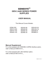
DC OUTPUT
The SM7.5-80, SM18-50, SM70-AR-24 and the SM400-AR-4
can either be used as a constant voltage source with current
limiting or as a constant current source with voltage limiting.
The change of mode occurs sharply at the crossing of the
voltage and current settings. Fig. 3 - 1 shows the output
ranges.
The SM70-AR-24 and the SM400-AR-4 feature an
AUTORANGING facility where the power supply
automatically switches over between two current ranges. This
switching, which is unnoticeable for the user, results in a
versatile power supply with twice the output voltage range.
This means that for the SM70-AR-24 the maximum output
power of 840 W is available at both 35 V and 70 V. For the
SM400-AR-4 this is 800 W at both 200 V and 400 V.
DISPLAY CV/CC SETTINGS FUNCTION
The settings of the voltage and current control (also when
programmed) can be observed on the front panel meters by
pressing the Display CV/CC Set- tings button. This allows the
current limit to be set when operating in the CV the voltage
limit to be set C mode without opening the load leads.
OVERLOAD PROTECTION
The power supply is fully protected against all overload
conditions, including short circuit.
3.2
AC INPUT VOLTAGE
The power supplies have a wide AC input voltage range.
The unit needs a single phase input voltage. At voltages
below about 100-110 VAC the output power has to be
derated, see specifications in the datasheet.
3.3
AC INPUT CURRENT
The unit has active power factor correction (PFC). The input
current will therefore almost be a sine wave. This means that
the RMS-value and the harmonic distortion of the AC input
current will be relatively low.
The peak inrush current is electronically limited. Switching on
and off repeatedly will not result in excessive currents like
with NTC circuits.
3.4
STANDBY AC INPUT POWER
The unit consumes very little power when in standby. This
makes it possible to leave the AC input power on when the
output is disabled using the Output On/Off push button on
front panel or the Remote ShutDown input (pin 5 on
connector CON E on the rear panel).
3.5
EFFICIENCY
The efficiency is very high and constant over a wide DC
output current range.
High efficiency means low power loss and low heat
generation.
3.6
CV REGULATION
The specified CV-load regulation value is measured directly
on the DC power terminals. This is because at high current, a
few cm of cable can have a voltage drop of several mV.
3.7
CC REGULATION
For accurate CC-load regulation, do not use external voltage
sensing.
A voltage between S- and minus output will create an error of
about 0.04 % per volt.
A voltage between S+ and + is not critical. The CC-stability is
also affected by external voltage sensing.
Note: when the unit operates in CC-mode, the DCF-LED will
be on. When the unit is in CC-mode most of the time, it is
possible to disable the LED with DIP switch 3 on SW1 (rear
panel).
fig 3 - 1
DC Output voltages and currents.
Every point in hatched area can be used
fig 3 - 3
Measuring ripple voltage
RIGHT!
fig 3 - 2
Measuring ripple voltage
WRONG!

GENERAL SM800
7 / 22 DELTA ELEKTRONIKA B.V. rev. Jan. 2022
3.8
RIPPLE & NOISE
The DC output ripple is very low with almost no spikes. The
specified ripple voltage is measured directly on the DC power
terminals using a probe with very short connections. This to
avoid pick up of magnetic fields, see fig. 3 - 2 and fig. 3 - 3.
At low temperatures like -20°C the ripple increases. By using
high quality electrolytic capacitors the increase is relatively
low.
3.9
ANALOG PROGRAMMING
The DC output voltage and current can be programmed by an
external analog voltage. This programming is very accurate
and linear. The levels are all standardized on 5 V.
For the other units, the inputs have a protection circuit formed
by a series resistor and a parallel zener (see fig. 3 - 4).
The capacitor limits the speed to a safe value. Note that the
analog inputs (and outputs) are not floating, but the
common is connected to the 'minus' DC output terminal.
Wrong connection of Ø can cause earth loops which can trip
the fuse. After removing the fault, the fuse will reset (PTC-
fuse). For isolated programming see next paragraph.
3.10
ISOLATED ANALOG PROGRAMMING
To prevent earth loops which can cause programming errors,
use an isolated programming source. If this is not possible,
use the optional ISO AMP CARD which can be built inside
the unit.
With the ISO AMP CARD earth loops between the unit and
the programming source are prevented.
3.11
ETH / IEEE488 / RS232 PROGRAMMING
The Delta Elektronika PSC-ETH, PSC-488 and PSC-232
controllers can be factory installed inside the unit.
Voltage and current can easily be programmed and read
back. Also all the status outputs can be read by the computer.
3.12
MONITORING OUTPUTS
The monitor outputs give a voltage 0 - 5 V proportional to the
output current or voltage. The output current can easily be
measured using the I-monitor (see fig. 3 - 6). The monitor
outputs are buffered with op-amp’s and protected with series
resistors and parallel zener diodes (see fig. 3 - 7). The table in
fig. 3 - 5 shows the impedance levels of the monitoring
outputs. For using Imon on a pulsating load, see paragraph
20) of this chapter.
3.13
+12 V ON PROGRAMMING CONNECTOR
The +12 V on the programming connector can be used to
supply external circuits. The output is current limited, but
should not be overloaded. The fuse F27_3 on P650 could
blow. The fuse F27_3 also protects the internal circuit, in case
an external high voltage is applied by accident. Note: this fuse
is a special 600 V type, always replace with the same type.
fig 3 - 4
Programming inputs (internal circuit).
fig 3 - 6
External meters using monitor
outputs.
pin
Description, see par.12)...17) for details
1
Ø, return of reference, prog. inputs and monitor
outputs (Ro = 1.2 Ohm).
2
current monitor output 0 - 5 V
(Ro = 1.2 Ohm, Io max = 4 mA)
3
current programming input (0 - 5 V),
Ri = 8 MOhm
4
CC status output, logic 1 = CC mode
(5 V / 500 Ohm)
5
Remote ShutDown (4 - 12 V),
Ri = 5 kOhm
6
PSOL status output, logic 1 = PSOL
(5 V / 500 Ohm)
7
+12 V output
(Ro = 3 Ohm, Io max = 0.2 A)
8
Ø, return of status outputs, +12 V
and Remote ShutDown
9
reference voltage 5.1 V
(Ro = 1.2 Ohm, Io max = 4 mA)
10
voltage monitor output 0 - 5 V
Ro = 1.2 Ohm, Io max = 4 mA)
11
voltage programming input (0 - 5 V)
Ri = 8 MOhm
12
OT - status output, logic 1 = OT
(5 V / 500 Ohm)
13
LIM - status output, logic 1 = LIM
(5 V / 500 Ohm)
14
DCF - status output, logic 1 = DCF
(5 V / 500 Ohm)
15
ACF - status output, logic 1 = ACF
(5 V / 500 Ohm)
fig 3 -5
Connections ANALOG PROG. CONNECTOR.
fig 3 - 7
Buffered monitor outputs.

GENERAL SM800
8 / 22 DELTA ELEKTRONIKA B.V. rev. Jan. 2022
3.14
STATUS OUTPUTS
All the status outputs are logic outputs. Logic "0" means the
output is 0 V, logic "1" means the output is 5 V (Ro = 500
Ohm). This makes it possible to drive directly: an opto-
coupler, a TTL gate or a CMOS gate.
The Limit Status or LIM-status is "1" in case the DC output
voltage or current reaches the limit setting. Which limit circuit
is active can be seen on the front panel LED’s.
The Over Temperature Status or OT-status is "1" in case of
an over temperature, the OT LED will be on and the output
shuts down. As a pre-warning the OT LED starts to blink
when the unit runs hot but the situation of over temperature is
not reached yet. The status will still be low when the LED is
blinking.
The Current Control Status or CC-status output is "1" when
the unit is in CC-mode.
The Power Sink OverLoad Status or PSOL-status output is
"1" when the optional Power Sink is overloaded or
overheated.
The AC-Fail Status or ACF-status output is "1" in case the
mains voltage is below 115 Vpeak (not Vrms) for more than
10ms. Note that if you want the ACF-status to switch before
the DCF-status, the hold-up time has to be >10ms. This can
be achieved by reducing the load, see paragraph 25) of this
chapter.
The DC-Fail Status or DCF-status output is "1" when the DC
output voltage is either 5% below or above the set point.
When the unit is in CC-mode, DCF will always be "1", see
previous paragraph .
fig 3 - 10
Status relay outputs on CON D. This situation gives
the relay positions during fault condition.
fig 3 – 8 Location of output terminals and analog programming connector on the rear panel.
CON A
Interlock Connector
CON B
Master connector for Master / Slave operation (output)
CON C
Slave connector for Master / Slave operation (input)
CON D
Relay Outputs, contacts 1 - 6
CON E
Analog Programming Connector ( not available when the optional ISO AMP or PSC-488 is installed, see CON H)
CON F
PSC-232, from PC or previous PSC (optional)
CON G
PSC-232, to next PSC (optional)
CON H
PSC-488 (optional) or ISO AMP CARD (optional) instead of CON E.
SW 1
Various settings, see table at the bottom of this page.
SW 2
Settings for PSC-488 and PSC-232 (optional)
fig 3 -9 Connectors and switches on the rear panel.
Switch no.
Left position
Right position
Default Setting
SW 1 – 1
Optional programming with e.g. PSC-232,
PSC-488, ISO AMP CARD.
Programming via 15pole connector CON E (analog).
Right
SW 1 – 2
‘Output Off’ after mains on
‘Output On’ after mains on
Left
SW 1 – 3
DCF LED disabled
(DCF status and DCF relay are still enabled)
DCF LED enabled
Right
SW 1 – 4
Series Master / Slave operation
Parallel Master / Slave operation
Right
SW 1 – 5*
After switching mains on, the unit will always
start up with a voltage setting of 0 V and a
current setting of 0 A. Once the unit is
switched on, the voltage and current can be
set to the preferred value.
After switching mains on, the unit will start with the
same settings for the voltage and the current as it had
before switching mains off
Left
* = SW1-5 only on units with optional digital encoders (option P236).
Numbering CON D.

GENERAL SM800
9 / 22 DELTA ELEKTRONIKA B.V. rev. Jan. 2022
3.15
STATUS RELAY OUTPUTS
The power supply has 2 status relay outputs, with each a
change-over contact. They are connected to connector CON
D. The pins 1,2,3 are connected to the DCF-relay and pins
4,5,6 to the ACF-relay (see fig. 3 - 8 and 3 - 10).
3.16
FUNCTION SWITCHES ON SW1
In the table on the previous page the functions of the DIP
switches 1-5 of switch SW1 at the rear side are explained.
3.17
REMOTE SHUTDOWN (RSD)
A voltage of +4...+12 V on the RSD input on the programming
connector CON E will switch off the output of the unit.
It is also possible to use a relay contact or a switch to shut the
unit down (see fig. 3 - 11). In standby mode the power supply
consumes very little power.
3.18
INTERLOCK
The Interlock connector CON A has 2 pins which have to be
connected together to enable the unit.
As soon this connection is interrupted, the DC output of the
unit shuts down. It can be used in combination with door
contacts (safety precaution) or as an emergency stop.
In case the connection is interrupted the RSD LED will light.
In contrast with Remote ShutDown, also the DCF LED will be
on, DCF status will be high and the relay contact will change.
Once the inputs are reconnected, the DC output will be on
again.
The interlock circuit is at the same level as the analog ground,
the S- and the minus DC power terminal. The interlock circuit
needs voltage free contacts and can not be connected in
parallel or series with other interlocks .
3.19
PROGRAMMING SPEED
The rise and fall time is measured with a step waveform at the
CV prog. input. Programming from a low to a high output
voltage is nearly load independent, but programming down to
a low voltage takes more time on lighter loads. This is caused
by the output capacitors, which can only be discharged by the
load because the power supply cannot sink current. With the
Power Sink option, also the programming down speed is
nearly load independent.
When having a unit with a high speed programming option,
the rise and fall time is 5 to 25 times faster (see datasheet).
The programming source must be floating or otherwise an
ISO AMP CARD must be used, a non-floating source will
result in slope distortion.
When using high speed programming it is generally not
recommended to use remote sensing or serial / parallel
operation. Consult factory for advice. Note that the output
ripple is higher.
3.20
PULSATING LOAD
To avoid overheating the DC output capacitors, the AC
component of the load current should be limited (fig. 3 - 13).
One method of decreasing the AC current through the output
capacitor is by using a large external electrolytic capacitor in
parallel with the load. Care must be taken so that the
capacitor in combination with the lead inductance will not form
a series resonant circuit!
When using remote sensing on a pulsating load (for instance
a DC-motor), use a capacitor in series with a resistor over the
load (see fig. 3 - 14). Like this the AC-component caused by
the pulsating of the load is filtered.
Note: in case of a pulsating load, the I monitor voltage will not
exactly match the output current. This is mainly caused by the
current through the output capacitors. Remote sensing will
worsen this effect.
3.21
INSULATION
For safety the insulation of the separating components
(transformers) between mains in and DC output is tested at
3750 Vrms during 1 minute. This is tested before assembly.
fig 3 - 11
Settings of DIP switch SW1.
fig 3 - 12
Remote Shut Down using a relay contact.
fig 3 - 13
Pulsating load current.
fig 3 - 14
Remote sensing on a pulsating load.
fig 3 - 15
Insulation test voltages.

GENERAL SM800
10 / 22 DELTA ELEKTRONIKA B.V. rev. Jan. 2022
Warning! The 3750 Vrms cannot be tested afterwards on the
assembled unit because the insulation between the
components on the AC side to the case (like the bridge
rectifier) is specified at 2500 Vrms. Since the insulation of DC
power terminals -> case is 600 VDC, the insulation of the
primary components to case will break down when 3750 Vrms
is applied between mains in and DC output (2500 Vrms + 600
VDC < 3750 Vrms). See also fig. 3 - 15.
Note: when testing the insulation, take care to charge and
discharge the capacitors between mains in - case and DC
output - case slowly (e.g. in one second). This to prevent high
peak currents, which could destroy the power supply. Make
sure to discharge the capacitors completely before using it
again.
3.22
RFI SUPPRESSION
Both the mains input and DC output have RFI filters, resulting
in very low conducted RFI to the line and load. Due to the
output filter, the output voltage is very clean with almost no
spikes.
3.23
OPERATING TEMP
At full power the operating temperature range is –20 to
+50 °C. From 50 to 60 °C the DC output current has to be
derated linearly to 75 % at 60 °C (see fig. 3 - 16). These
temperatures hold for normal use, i.e. the ventilation openings
on the left and right side must be free.
3.24
THERMAL PROTECTION
A thermal switch shuts down the DC output in case of
insufficient cooling. The OT status will be high. After cooling
down the unit will start working again.
The OT-LED on the front panel will be on and the OT-status
signal will be "1" in case of a tripped thermal protection.
As a pre-warning the OT-LED blinks (status will still be low),
this will start before the power supply shuts down.
3.25
HOLD - UP TIME
The hold - up time depends on the load and the DC output
voltage.
A lighter load or a lower DC output voltage results in a longer
hold - up time (see fig. 3 - 17).
3.26
TURN ON DELAY
The DC output voltage is available about 0.2 sec after mains
switch on.
3.27
AC INRUSH CURRENT
The inrush current is electronically limited.
Repeatedly switching on and off does not change the
maximum peak current.
Switching on and off at a fast rate can overheat the inrush
current limiter. With the result that the unit does not start
anymore. After cooling down (mains switched off) it will be OK
again.
3.28
DC LOAD SENSING (REMOTE SENSING)
The DC voltage at the load can be kept constant by remote
sensing. This feature is not recommended for normal use but
only when the load voltage is not allowed to vary a few
millivolts. Always use a shielded cable for sensing.
In order to compensate for voltage drop across the load
leads, the unit will have to supply a higher voltage (fig. 3 - 18):
* Uout = (voltage drop across each lead) + (voltage across the load).
The voltage limit reads the voltage directly at the output
terminals. The setting for the limit must therefore be increased
by the total voltage drop across the load leads.
The voltage display on the front panel and the voltage monitor
output on CON E are connected to the sense leads and
therefore read the voltage across the load and not the voltage
on the DC output terminals.
fig 3 - 16
Operating temperature ranges.
fig 3 - 17
Hold-up time vs Vout with Iout as a parameter.
fig 3 - 18
Remote sensing, voltage drop in load leads subtracts
from maximum output.

GENERAL SM800
11 / 22 DELTA ELEKTRONIKA B.V. rev. Jan. 2022
The sense leads are protected against accidental interruption.
The maximum voltage between the DC output terminals and
the sense inputs is limited at 2.5 V.
For sensing on a pulsating load see paragraph 20) of this
chapter.
3.29
SERIES OPERATION
Series operation is allowed up to 600 V total voltage. The
power supplies can be connected in series without special
precautions.
For easier control, Master / Slave operation is recommended
(see fig. 3 - 19).
By using the Master / Slave series feature a dual tracking
power supply can be made with one unit as master and one
as slave.
For series operation in combination with Power Sink option,
all units must have a Power Sink built inside otherwise no
power can be absorbed.
3.30
PARALLEL OPERATION
Paralleling of the units has no limitations. The power supplies
can be connected in parallel without special precautions. For
easier control, Master / Slave operation is recommended
(see fig. 3 - 19 and fig. 3 - 20).
Normal parallel operation of High Speed Programming units
can give problems, each combination has to be tested first, in
combination with the load !
For parallel operation in combination with Power Sink option,
only one unit can have a Power Sink. Refer to Power Sink
manual for details and restrictions.
3.31
MASTER / SLAVE OPERATION
The Master / Slave feature makes it possible to use power
supplies as building blocks to form one large unit (fig. 3 - 20).
Mixed parallel - series operation is also possible, to a
maximum of 600 V.
The resulting combination of units behaves like one power
supply and can be manually controlled or programmed on the
master. Figure 3 - 21 shows a computer controlled Master /
Slave parallel combination.
Connect the different units with standard RJ45 cables (see
fig. 3 - 22), using CON B and CON C on the rear side. With
DIP switch 4 of switch SW1 the Parallel or Series mode can
be selected.
The slaves will follow the master. The result is true current or
voltage sharing in the parallel or series mode respectively.
Note: Master / Slave parallel operation is not recommended
for more than 4 units or in combination with High Speed
Programming option. Consult factory for a solution.
fig 3 - 19
Master / Slave series operation.
fig 3 - 20
Master / Slave parallel operation.
fig 3 - 21
The Master / Slave combination can also be
programmed with the interfaces PSC-488 or the
PSC-232.
fig 3 - 22
Use standard UTP cables
(RJ45) for Master / Slave
operation.
Master Unit:
Connect CON B to Slave1.
Slave unit:
Connect CON C to Master.
Connect CON B to Slave2.
Warning:
Never connect CON C
to CON C!
See next chapter for
more details.

GENERAL SM800
12 / 22 DELTA ELEKTRONIKA B.V. rev. Jan. 2022
3.32
DC VOLTAGE AND CURRENT LIMIT
The Voltage Limit will protect your circuit from unwanted high
voltages. A high DC output voltage could be caused by
accidental interruption of leads, accidentally turning up the
voltage potmeter, a programming error or a defect in the
power supply. The Voltage Limit circuit uses a separate
voltage divider connected directly to the output terminals.
The Current Limit protects your circuit from unwanted high
currents.
The Voltage and Current Limits maintain the output to a safe
preset value.
They do not trip, so no resetting is needed after a fault. It can
be very handy to have hardware limits when the power supply
is programmed.
The limits can easily be set by pressing the DISPLAY LIMITS
button and adjusting the potentiometers with a screwdriver.
The LED’s next to the potmeters indicate the activity of each
limit, also the LIM-status output will be "1".
3.33
POTENTIOMETERS AND ENCODERS
At the front panel, standard every unit is equipped with knobs
for the CV and CC controls and with screwdriver adjustment
for the Voltage and Current Limit.
Optional there is the possibility for digital encoders for the
CV/CC-controls, with a very long life time and intelligent
functions such as variable coarse/fine pitch adjustment,
locking of CV/CC-settings and a selectable start-up voltage
(start at 0V/0A or at last settings).
The standard units have analog potentiometers for the
CV/CC-controls . Optional they can be equipped with
screwdriver adjustment for CV/CC-settings at the front panel
or also with digital encoders (option P236). See fig. 3 - 23 for
option P001.
3.34
COOLING
A low noise blower cools the unit. The speed of the fan
depends on the temperature of the internal heatsink. Normally
at 50 °C ambient and full load the fan will not work at full
speed.
A special feature is that the fan blows through a tunnel where
the heatsinks are situated, the delicate control circuitry is
separated and will not be in the airflow path (see fig. 3 - 24).
Because the air enters at the rear and exits at the sides, it is
possible to stack the power supplies, no distance between the
units is required. Only the ventilation openings at the rear and
either left or right side should be free.
For long life the temperature of the air entering at the rear
should be below 35 °C under normal conditions. Under
extreme conditions it should be below 50 °C.
3.35
DIMENSIONS
fig 3 - 23
Screwdriver adjustment at front panel.
fig 3 - 24
The fan blows through the tunnel, where the
heatsinks are situated. Take care to leave at least
one air outlet unobstructed.
fig 3 – 25 Unit dimensions.

INSTALLATION SM800
13 / 22 DELTA ELEKTRONIKA B.V. rev. Jan. 2022
4
INSTALLATION
Warning! carefully read the chapter "Safety Instructions" in
this manual before connecting or operating the unit!
4.1
HUMIDITY & CONDENSATION
During normal operation, humidity will not harm the power
supply, provided the air is not aggressive. The heat normally
produced in the power supply will keep it dry.
Avoid condensation inside the power supply, to prevent
break-down. Condensation can occur during a period the
power supply has been switched off (or operating at no load)
and the ambient temperature is increasing. Always allow the
power supply to dry before switching it on again.
4.2
TEMPERATURE & COOLING
The storage temperature range is –40 to +85 °C.
The operating temperature range at full load is –20 to +50 °C.
This temperature range only holds when the air-intake and
air-outlets are unobstructed and the temperature of the air-
intake is not higher than +50 °C.
When the power supply is mounted in a cabinet, please note
that the temperature of the air-intake should be kept low and
avoid a short circuit in the airflow i.e. the hot air leaving the
air-outlets entering the air-intake again.
Please note: a lower temperature extends the lifetime of the
power supply.
4.3
19" RACK MOUNTING
On both sides in the rack, mount a proper support slide that
can hold the weight of the unit. It is advised to use a separate
slide for each unit.
After placing the unit on the slide, add all 4 screws to mount
the front panel of the power supply to the vertical rack posts.
Use proper screws intended for keeping equipment of this
weight in position.
Assuming the rack is deliberately designed for the weight,
stacking of the units is allowed without limitations. See
previous paragraph for cooling instructions.
4.4
OPERATING THE UNIT FOR THE FIRST TIME
Check there is no condensation on the unit. If there is, allow
some time to dry.
Check there is a link between + and S+ and between – and
S– on the SENSE BLOCK (on rear panel).
Check there is a link between pins of the Interlock (CON A).
Set the CV and CC potentiometers to minimum (fully anti
clockwise). For units with Option P236, this is not needed.
These units are set to start at 0 V - 0 A when operated for the
first time.
For the AC mains, connect a cable that is designed for use at
10 A with the specific AC input appliance coupler.
For the DC output power, see table 4 - 1 for cable diameters
and mounting torque.
For high DC current make sure to use low resistive
connections between the power supply and the load:
- Mount the cable lugs directly on the DC output strips
followed by a washer, split washer and a nut (see fig. 4 - 1).
Always in this order!
- Never place washers between the lugs and the strips
because this can result in excessive heat!
- Only use nuts and washers supplied with the unit.
Switch on unit.
Disable the Keylock function, see next paragraph.
Check the unit is not in Remote CV or Remote CC (LED’s for
this function should be off). Press the REMOTE/LOCAL
button until both LED’s are off.
Turn on DC output by pressing the OUTPUT ON/OFF button.
Turn both the CV and CC potentiometer a few turns
clockwise.
A voltage should now be present on the output.
By pressing the DISPLAY CV/CC SETTING button the meters
will show the setting of the CV and CC potentiometer.
fig 4 - 1
Low resistive cable connection by mounting the
cables directly on the DC output strips.
Unit
DC Output
cable [mm2]
Bolts
Torque
[Nm]
SM7.5-80
16
M5
5
SM18-50
10
M5
5
SM70-AR-24
4
M5
5
SM400-AR-4
1
M5
5
table 4 -1
Recommended cable diameters and mounting torque.

INSTALLATION SM800
14 / 22 DELTA ELEKTRONIKA B.V. rev. Jan. 2022
By pressing the DISPLAY LIMITS button the voltmeter will
show the setting of the CV-limit and the CC-limit
potentiometer.
Check that the cooling of the unit is not obstructed.
4.5
KEYLOCK
If the function KEYLOCK is activated, it is no longer possible
to operate the REMOTE/LOCAL button and the OUTPUT
ON/OFF button. This function can be useful to protect the
output from accidental shutdown. The function KEYLOCK
does not influence the operating of the CV, CC, CV-limit and
CC-limit potentiometers.
Units with digital encoders:
For units with Option P236, also the digital encoders for CV
and CC are disabled with the Keylock function. This means
settings of the voltage and current do not change when the
encoders are operated. It is still possible to operate the
analog CV-limit and CC-limit potentiometers.
Activate Keylock:
Pressing the buttons DISPLAY SETTINGS and DISPLAY
LIMITS at the same time for more than 3 seconds, activates
the function KEYLOCK. The moment this function is
activated, the LED’s for REMOTE CV / CC and for OUTPUT
ON will blink a few times.
Disable Keylock:
Pressing the same buttons again for 3 seconds, disables the
Keylock function. The LED’s for REMOTE CV / CC and for
OUTPUT ON will blink again to indicate the new setting.
4.6
SELECT START-UP MODE
The below is only applicable for units with magnetic encoders
- option P236:
- Setting switch SW1-5 at the rear panel in position Left,
the unit will always start at 0V / 0A after mains switch on.
- Setting switch SW1-5 in position Right, the settings after
mains switch on will be the same as before switching the
mains voltage off.
4.7
ANALOG PROGRAMMING
Set DIP switch 1 of SW1 in position Right to select CON E for
programming.
Disable Keylock.
Set the unit in REMOTE CV for voltage programming and/or
in REMOTE CC for current programming.
Use the REMOTE/LOCAL button and push this button several
times until the correct setting is activated.
Note that pushing the REMOTE/LOCAL button will shutdown
the output to avoid accidental damage to the load.
Connect the programming voltage source(s) (0 - 5 V) to the
analog programming connector CON E on the rear panel (see
fig. 4 - 2 and fig. 4 - 3). Always use a shielded cable (max.
30 meter) for programming.
Turn the output on again with the OUTPUT ON/OFF button.
If only the voltage is programmed, the maximum current can
still be set with the CC knob on the front panel and vice versa.
If this is not desirable the unit can be ordered with Option
P001 or Option P236 in order to have a fixed setting for the
CV and the CC knob on the front panel, see also paragraph
34) in previous chapter "General".
To avoid hum or noise, the programming cable may have to
be twisted in some cases.
To program the unit by current instead of voltage, simply use
a parallel resistor as a current to voltage converter.
Pressing the DISPLAY SETTINGS button will show the
programmed values for CV and CC.
Warning: The analog inputs are not isolated from the output.
The Ø of the prog. input (pin 1) is internally connected to the
S–, the S– is connected to the negative output. To protect the
internal wiring a 650 mA self-resetting fuse is connected in
series (F27_1 on P650). To avoid earth loops, use an isolated
programming source. If this is not possible, see next
paragraph for using the optional ISO AMP CARD.
fig 4 - 2
Programming by voltage:
left voltage -, right current programming.
fig 4 - 3
Programming by current:
left voltage -, right current programming.
fig 4 - 4
Remote control.
fig 4 - 5
Local sensing.

INSTALLATION SM800
15 / 22 DELTA ELEKTRONIKA B.V. rev. Jan. 2022
4.8
ISOLATED ANALOG PROGRAMMING
For programming via the ISO AMP CARD, set DIP switch 1
on SW1 in the position Left.
When the ISO AMP CARD is built inside the unit, CON E has
been covered or removed. Use CON H instead. The pinning
of CON H is equal to the pinning of CON E.
For further operating instructions, see previous paragraph.
4.9
IEEE488 / RS232 PROGRAMMING
Set DIP switch 1 on SW1 in position Left for programming
with the PSC-488 using CON H or programming with the
PSC-232 using CON F and G. With DIP switch 1 in this
position, the signals Vprog (pin 11) and Iprog (pin 3) are disabled
on CON E. All the other signals can still be used.
Set the unit in REMOTE CV for voltage programming and/or
in REMOTE CC for current programming using the SCPI
commands (see manual PSC) or using the REMOTE/LOCAL
button on the unit. Push this button several times until the
correct setting is activated. Setting the unit in REMOTE or
LOCAL will cause the output to shutdown to avoid accidental
damage to the load. Turn it on again using the SCPI
command or with the OUTPUT ON/OFF button.
Set DIP switch 1 on SW1 in position Right to enable CON E
again for analog programming. In this position voltage and
current programming on CON F and H is disabled. The other
functions and signals can still be programmed and read back.
4.10
MONITORING OUTPUTS
The 5 V level is compatible with most interfaces.
The monitoring outputs can drive a meter directly (fig. 4 - 4).
4.11
STATUS OUTPUTS
The status outputs have a separate Ø connection (pin 8) to
avoid unwanted offsets in the programming. This pin is
protected with a 650 mA self resetting fuse (F27_2 on P650).
4.12
DC LOAD SENSING (REMOTE SENSING)
Remove the links on the SENSE BLOCK (on rear panel) and
connect sense leads (thin shielded measuring wires) to S+
and S–. See fig. 4 - 5 and fig. 4 - 6.
With remote sensing the voltage on the load can be kept
constant. The voltage drop in the load leads will be
compensated. This feature is not recommended for normal
use, because it can easily give problems.
Max. 2 V per load lead can be compensated. Note that the
voltage drop in the leads decreases the max. output voltage
rating. In fig. 4 - 7 it can be seen that on a 15 V power supply
only 11 V will be available on the load when 2x 2 V
compensation is used.
In order to prevent interference it is advisable to twist the
sense leads. To minimize the inductance in the load leads
keep the leads close to each other. The inductance of the
loads leads could give a problem with pulsating loads. In this
case a large electrolytic capacitor (Cd) in series with a
damping resistor (Rd) both in parallel with the load will help
(see fig. 4 - 6). Check that the capacitor Cd in combination
with the load leads and resistor Rd forms a well damped
circuit.
Since the voltmeter is internally connected to the sensing
terminals, it will automatically indicate the voltage on the
load. Note that the voltage measured on the load will be
lower than on the output terminals.
The Over Voltage Limit measures the voltage on the output
terminals, so the OVL setting should be increased by the total
voltage drop in the load leads.
4.13
BATTERY CHARGER
The CV / CC regulated power supplies are ideal battery
chargers. Once the output is set at the correct voltage the
battery will charge constantly without overcharging. This can
be useful for emergency power systems.
fig 4 - 6
Remote sensing with shielded wires.
fig 4 - 7
remote sensing, voltage drop on load leads subtracts
from the maximum output.
fig 4 - 8
Charging a battery with a circuit breaker in series.
Suggested circuit breakers for protection power supply
Model
Type nr.
Brand
Remarks
SM7.5-80
S281 UC-B100
ABB
-
SM18-50
S281 UC-Z 63
ABB
-
SM70AR-24
S281 UC-Z 25
ABB
-
SM400AR-4
S281 UC-Z 6
ABB
extra parallel diode
on output needed
2x BYT261 in series
table 4 -2
Circuit breakers for protection.

INSTALLATION SM800
16 / 22 DELTA ELEKTRONIKA B.V. rev. Jan. 2022
Protective measures
Use a CIRCUIT BREAKER in series in order to protect the
power supply from accidental reverse connection (see fig. 4
- 8).The circuit breaker should have a DC voltage rating twice
the battery voltage. Use the very fast type (Z), a type meant
for protecting semiconductors (see table 4 - 2).
The unit has a reverse diode in parallel with the DC output,
this diode and the wiring cannot withstand the thousands of
amperes supplied by a wrongly connected battery.
4.14
REMOTE SHUTDOWN
The Remote ShutDown can be operated on CON E by a
voltage of +4 V...+12 V or by a relay contact between Vref
and Remote ShutDown (pin 9 and 5) (see fig. 4 - 9).
When the unit is programmed with an optional PSC, a
software command can be used for Remote Shutdown.
In the Remote ShutDown condition, the RSD LED will be on.
The DCF LED, DCF status and the DCF relay will be off.
Important: If the link from the Interlock connector (CON A)
has been removed, the RSD LED will be on, but in this
condition also the DCF LED, the DCF status and the DCF
relay will be on.
4.15
MASTER / SLAVE SERIES OPERATION
Connect output terminals and test system in normal series
operation. Ensure that all DC power connections are reliable.
The voltage drop in the connecting leads between the units
should be kept < 10 mV.
Switch off all units. Connect units as shown in fig. 4 - 10.
To connect the slaves with the master via CON B and CON
C, use standard UTP cables (RJ45).
On all units put DIP switch 4 of SW1 in position Left to set the
units in M/S series mode.
After turning the units on again, the slaves will be in Remote
CV mode and the Keylock (see previous paragraph is
activated. This is because the unit automatically detects the
presence of the RJ45 connector in CON C (if this cable is
connected to another unit).
If the RJ45 connector is removed from CON C when the unit
is turned on, the DC output will shutdown to avoid accidental
damage.
If the cable is inserted when the unit is turned on, the DC
output shuts down, the unit changes to Remote CV / CC, the
Keylock will be activated and the output will turn back on.
If DIP switch 4 of SW1 is operated when the unit is turned on,
the DC output will shutdown to avoid accidental damage.
The maximum number of slaves is only limited by the
maximum total voltage of 600 V.
4.16
MASTER / SLAVE PARALLEL OPERATION
Note: Master / Slave parallel is not recommended for
more than 3 units, consult factory for using more than 3
power supplies in parallel.
First connect the DC power terminals and test system in
normal parallel operation. Ensure that all power connections
are reliable.
Second, switch off all units. To connect the slaves with the
master via CON B and CON C, use standard RJ45
connectors according to fig. 4 - 11.
On all units put DIP switch 4 of SW1 in position Right to set
the units in M/S parallel mode. In this mode the DCF LED,
DCF relay and DCF status on the slaves are disabled
because the slaves are always in CC mode.
After turning the units on again, the slaves will be in Remote
CC mode and the Keylock (see previous paragraph 5) is
activated. This is because the unit automatically detects the
presence of the RJ45 connector in CON C (if this cable is
connected to another unit).
If the RJ45 connector is removed from CON C when the unit
is turned on, the output will shutdown to avoid accidental
damage.
fig 4 - 9
Remote Shutdown with switch.
fig 4 – 10
Master / Slave series connections.
fig 4 - 11
Master / Slave parallel connections.

INSTALLATION SM800
17 / 22 DELTA ELEKTRONIKA B.V. rev. Jan. 2022
If the cable is inserted when the unit is turned on, the output
shuts down, the unit changes to Remote CV / CC, the
Keylock will be activated and the output will turn back on.
If DIP switch 4 of SW1 is operated when the unit is turned on,
the output will shutdown to avoid accidental damage.
Stack the units to create a minimum distance between the
units. Keep the load close to the master.
Use copper strips (preferred) or short thick cables to connect
the units. Make sure the strips are mounted with a minimum
length to keep the voltage drop between a unit and the bus
bar below 10 mV. Also keep the strips close to each other to
have a low inductance.
Not following these instructions can cause instability.
The S- and S+ could be connected to the load if desired, but
this is not recommended because of the complexity and
possible instability.
4.17
PARALLEL OPERATION OF HIGH SPEED
PROGRAMMING VERSIONS:
Master / Slave operation is not recommended.
Normal parallel operation can give problems, each
combination has to be tested first in combination with the
load.
4.18
MASTER / SLAVE MIXED SERIES / PARALLEL
OPERATION
For complex combinations as mixed series - parallel, always
use a MASTER / SLAVE SERIES ADAPTER.
See fig. 4 - 12 for an example of how to connect 2 units in
series in parallel with 2 units in series, controlled by 1 master.
Set the programming mode with the knob Remote / Local on
the front panel. The serial slaves must be in Remote CV- and
CC-mode. The parallel slave must be in Remote CC-mode
and the CV-potmeter must be fully opened.
Note: A Master / Slave combination can always be
programmed, also with the IEEE488/RS232 controller (PSC-
488 / PSC-232).
.
fig 4 - 12
Master / Slave mixed series – parallel connections.

TROUBLE SHOOTING SM800
18 / 22 DELTA ELEKTRONIKA B.V. rev. Jan. 2022
5
TROUBLE SHOOTING
5.1
GENERAL
If you have a question about the unit, please contact our
engineers using the address [email protected].
In case the unit is defect, please first fill out the RMA-form
before sending the unit to us. Adding a detailed fault
description will help us to repair the unit as soon as
possible. Do not try to repair the unit yourself.
On our website the RMA-form can be found under
'Support'.
5.2
NO DC OUTPUT (manual control)
Check the LED’s ‘Remote CV’ and ‘Remote CC’ on the
front panel, they should be off. Disable Keylock and press
the REMOTE/LOCAL switch to turn both LED’s off.
The LED ‘Output On’ should be on. If this LED is off,
disable Keylock and push the button ‘OUTPUT ON/OFF’.
Check the connections on the SENSE BLOCK (at rear
panel), there should be a link between + and S+ and
between – and S– (see fig. 5 - 3).
Check if there is a link in the Interlock connector (if not, the
RSD LED will be on).
Set both the CV- and CC-limit potentiometer (at front panel)
at maximum (fully clockwise).
Turn both the CV and CC potentiometers a few turns
clockwise.
A voltage should be present on the output (for units with
Option P236 first remove the Keylock function before the
CV and CC knobs can be turned, see par.5 in previous
chapter "operating manual").
Turn both the CV and CC potentiometers a few turns
clockwise. A voltage should be present on the output.
5.3
PROGRAMMING DOES NOT WORK OK
Check the unit is in Remote mode (Remote CV and/or
Remote CC LED should be on).
The unit works OK in manual control, but in programming
mode the output voltage / current has a large error.
Probably the fuse in series with Ø (pin 1) of programming
connector tripped, the fuse (F27_1 = 650 mA) is a self-
resetting type (see fig. 5 - 1).
To check the fuse (F27_1) measure the voltage between Ø
and the minus output, during the fault condition. The
voltage should only be a few mV, a high voltage means that
an unwanted current is flowing through pin 1 of the prog.
connector.
Please check why current is flowing through pin 1, see also
next paragraph and fig. 5 - 2.
5.4
PROGRAMMING OFFSETS
Unwanted offsets in the programming can be caused
by earth loops.
Figure 5 - 2 shows a typical earthing problem. In case the
load has a connection to earth and the programming
source as well, problems could occur. Improper choice of
the earthing point of the load can give a voltage drop of
ΔV1. Connecting the minus or zero to a separate earth
connection can give a voltage drop of ΔV2. Because the
internal wires of the programming input are thin, the voltage
drops ΔV1 and ΔV2 will be across the internal wiring as
well. Resulting in an error voltage in series with the
programming voltage.
The best solution for this is to use a floating programming
source, a floating load or the optional internal ISO AMP
CARD.
5.5
STATUS OUTPUTS FAIL
Check fuse F27_2 in series with Ø (pin 8 of CON E), see
fig. 5 - 1. To check the fuse measure the voltage between
Ø and the minus output, a high voltage means too much
current flowing through the fuse. F27_2 = 650 mA, self
resetting.
fig 5 - 2
Unwanted programming offsets.
fig 5 - 1
Location of programming fuses on P647.
P647 is situated directly behind the rear panel.

TROUBLE SHOOTING SM800
19 / 22 DELTA ELEKTRONIKA B.V. rev. Jan. 2022
5.6
MASTER / SLAVE PARALLEL PROBLEMS
Check the voltage drop of the wiring between the master and
the slaves is < 10 mV.
Check the wiring has a low inductance.
5.7
DC OUTPUT VOLTAGE IS HIGHER THAN SET
VALUE
Check connections on SENSE BLOCK (on rear panel), For
normal operation there should be a link between + and S+
and between – and S– (see also fig. 5 - 3). When remote
sensing is used, check the wires of the sensing.
5.8
OT LED on
The temperature of the internal heat sink is too high, the
output has been shutdown to avoid overheating.
Check if the cooling fan is running.
Check if the air temperature of the air inlet (rear side) is below
50 °C and the airflow is not obstructed.
5.9
OT LED blinks
The temperature of the internal heat sink is getting too high, a
further increase will shutdown the power supply.
Check if the cooling fan is running properly.
Check if the air temperature of the air inlet (rear side) is below
50 °C and the airflow is not obstructed.
5.10
ACF LED on
The input voltage is too low or was intermittent because of a
bad connection. Disconnect the mains, wait a few minutes
and try again.
Note the following:
As soon as the ACF LED is on, the settings for Remote CV,
Remote CC and Keylock will be saved. If the unit turns back
on, it will have the same settings. For the setting of Output
On/Off after turning the unit back on, the position of DIP
switch 2 on SW1 is determining.
If the ACF situation lasts a few seconds, the output will
shutdown. The ACF problem has to be solved first, before the
output can be turned on again.
Internal error, send unit for repair. See paragraph 1).
5.11
DCF LED on
The output voltage is below the set voltage. This
automatically happens when the unit is in CC-mode (CC LED
is on).
Also with an interrupted Interlock connector, the DCF LED will
be on.
Internal error, send unit for repair. See paragraph 1).
5.12
PSOL LED on
The Power Sink is in overload or the temperature of the
Power Sink is too high. See datasheet of the Power Sink
option for further details.
5.13
Blinking LEDs REMOTE CV, REMOTE CC and
OUTPUT ON
This indicates the Keylock function is activated, see previous
paragraph 5) in "operating manual".
5.14
NO LEDS on
Check input.
Do not try to repair, but send for repair. See paragraph 1).
5.15
Other
If the problem persists, please fill out the RMA-form on our
website www.DeltaPowerSupplies.com. See previous
paragraph 1).
fig 5 - 3
For normal operation links should be connected
between S+ and +, and between S- and -.

MAINTENANCE & CALIBRATION SM800
20 / 22 DELTA ELEKTRONIKA B.V. rev. Jan. 2022
fig 6 -1
The fan is located at the rear side and blows
through the tunnel.
6
MAINTENANCE & CALIBRATION
6.1
GENERAL
The SM-series power sup plies do not need any maintenance
or calibration. However, care must be taken that the cooling of
the unit is not obstructed.
6.2
COOLING FAN
The built up of dust on the impeller of the fan and the heat
sink fins depends on the environment. Since the fan has over-
capacity, dust will not present a problem very quickly.
The internal construction of the power supply is such that no
dust will reach the sensitive control circuitry, only the heat
sink in a tunnel will be cooled by forced air (see fig. 6 - 1).
The thermal protection will shut down the out put in case of
over heating, so the power supply will not be damaged.
It is advisable to inspect the fan and the heat sink regularly.
6.3
GALVANIC INDUSTRY
For using the power supplies in the galvanic industry it is
strongly recommended to take precautions against an
aggressive environment.
An aggressive environment with acid, salt, etc. can harm the
electronic components. Some times even the copper tracks
on the printed circuit boards dissolve.
To avoid problems, the power supplies should be mounted in
a relatively clean room, or mounted in a cabinet receiving
clean air with over pressure, or a cabinet with a heat
exchanger.
6.4
CALIBRATION
The power supplies are factory calibrated and normally need
no further calibration.
Only in special situations, for example after repairing a unit,
calibration can be necessary.
6.5
METER CALIBRATION
DIGITAL METERS
The full scale indication can be calibrated with R25_31
and R25_36 on P673 (see fig. 6 - 2).
6.6
SPECIAL CALIBRATIONS
The following calibrations must be done by qualified
personnel only. Wrong calibration causes malfunction. These
calibrations are only needed after special repairs.
Warning ! Damage caused by a wrong calibration is not
warranted.
CALIBRATING THE CURRENT MONITOR OFFSET.
With R26_73 on P650 the offset of the CC monitor voltage can
be calibrated (see fig. 6 - 3). The unit has to be unloaded, the
output voltage has to be turned off using the OUTPUT
ON/OFF button. Measure the offset voltage of the CC monitor
on the programming connector. Calibrate the offset on a
negative value between –1 mV and zero mV.
Warning! wrong calibration can damage the unit.
CALIBRATING MAX. CURRENT RANGE or CALIBRATING
CC MONITOR FULL SCALE.
Short the output using a low resistive cable. Measure the
output current with an accurate shunt. The maximum output
current can be calibrated with R26_41. R26_41 is located
on P650 (see fig. 6 - 3).
Program CC input with exactly 5.00 V.
Set output voltage to a high value, ensuring the power supply is
in CC mode. Calibrate the current with R26_41 exactly on the
rated max. current.
Warning! Wrong calibration can damage the unit.
fig 6 -2
Meter calibration with 25-turn potmeters on P673.
fig 6 -3
Calibrating maximum current and offset on P650.
V-meter
A-meter
/