Elster ACM M-BUS WIRE, ACM SCR+ WIRE Operating instructions
- Type
- Operating instructions

Edition 02.10
© 2008-2010 Elster GmbH
➔ www.docuthek.com
GB NL SKD Please read and keep in a safe place
Please read through these instructions
carefully before installing or operating. Following the
installation, pass the instructions on to the opera-
tor. This unit must be installed and commissioned
in accordance with the regulations and standards
in force. These instructions can also be found at
www.docuthek.com.
Explanation of symbols
• , 1 , 2 , ... = Action
▷ = Instruction
Liability
We will not be held liable for damage resulting from
non-observance of the instructions and non-com-
pliant use.
Safety instructions
Information that is relevant for safety is indicated in
the instructions as follows:
DANGER
Indicates potentially fatal situations.
WARNING
Indicates possible danger to life and limb.
CAUTION
Indicates possible material damage.
All interventions may only be carried out by qualified
gas technicians. Electrical interventions may only be
carried out by qualified electricians.
Conversion, spare parts
All technical changes are prohibited. Only use OEM
spare parts.
Transport
On receipt of the product, check that the delivery is
complete (see Part designations). Report any trans-
port damage immediately.
Storage
Store the product in a dry place. Ambient tempera-
ture: see Technical data.
Disposal
Components are to be disposed of separately.
On request, old units may be returned carriage paid
to Elster GmbH in accordance with the relevant waste
legislation requirements (for Germany: KrW-/AbfG
[Act for Promoting Closed Substance Cycle Waste
Management and Ensuring Environmentally Compat-
ible Waste Disposal]).
Operating instructions
Translation from the German
D
GB
F
NL
I
E
GB-1
Safety
Contents
Communications module
ACM M-BUS WIRE,
ACM SCR+ WIRE for gas meters
with Absolute ENCODER AE2 with
and without smart valve
Communications module
ACM M-BUS WIRE,
ACM SCR+ WIRE for gas meters with
Absolute ENCODER AE2 with and without
smart valve ............................1
Contents ..............................1
Safety.................................1
Checking the usage .....................2
Type code .............................2
Part designations ........................2
Wiring ................................2
Installation ............................
Installing the gas meter ...................3
Attaching the ACM..WIRE .................3
Commissioning.........................
Synchronization .........................3
Charging time ..........................3
Replacement...........................
Maintenance ...........................
Assistance in the event of malfunction .....
Technical data .........................4
Declaration of conformity ................4
Contact ...............................4

GB-2
D
GB
F
NL
I
E
Checking the usage
Communications module ACM..WIRE for gas
meters with Absolute ENCODER AE2
Communications module ACM..WIRE for recording
and forwarding absolute meter readings.
ACM M-BUS WIRE additionally offers the “V-Drive”
option. This means that activation and status mes-
saging of the valve incorporated in the gas meter can
be carried out. The valve is designed for the remote
connection and disconnection of the gas supply.
This function is only guaranteed when used within the
specified limits – see page 4 (Technical data). Any
other use is considered as non-compliant.
Type code
Code Description
ACM Absolute ENCODER
communications module
M-BUS
SCR+
M-BUS bus system
SCR+ interface
WIRE Cable-based version
V-Drive Smart valve control (M-BUS)
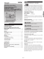
Part designations
3
2
14
5
1 Gas meter
2 Absolute ENCODER AE2
ACM M-BUS WIRE/ACM SCR+ WIRE
4 Retaining screw (at the rear of the ACM..WIRE)
5 Calibration seal (at the rear of the ACM..WIRE)
Wiring
WARNING
Electric shocks can be fatal! Before working on
possible live components ensure the unit is discon-
nected from the power supply.
▷
For the electrical connection between the
ACM..WIRE and the receiving unit, polarity is
inconsequential.
1 Wire the ACM..WIRE to the receiving unit.
▷
If a connection cable is already routed to the
receiving unit at the installation location, the pre-
fabricated connection cable on the ACM..WIRE
may be removed, as described below.
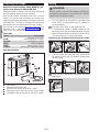
Removing the prefabricated connection cable
4 5 6
2 3
1
▷Use the connection plug from the ACM..WIRE
for further wiring with the already routed con-
nection cable.
456
2 3
1
7 Feed the new connection cable into the strain
relief facility.
4 5 6
2 3
1

GB-3
D
GB
F
NL
I
E
Installation
Installing the gas meter
▷
For installing the gas meter in the pipework, refer
to the operating instructions for diaphragm me-
ters BK-G1.6 to BK-G25T, see www.docuthek.
com → Elster-Instromet → Products → Gas
measuring devices → Diaphragm meters →
Diaphragm meters BK-G1.6 to BK-G25T op-
erating instructions.
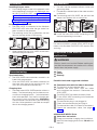
Attaching the ACM..WIRE
▷
The ACM..WIRE is connected to the Absolute
ENCODER AE2 index after the gas meter has
been installed in the pipework.
▷
The retaining screw and a calibration seal are
found at the rear of the ACM housing.
6
123
4 5
▷When connecting the ACM..WIRE to the index,
avoid bending the contacts.
6
123
4 5
Commissioning
Synchronization
▷The ACM..WIRE communications module is de-
livered fully programmed.
▷
Once the ACM..WIRE has been connected to
the index and wired to the receiving unit, the
units are synchronized automatically.
Charging time
▷
The cable-based ACM..WIRE operates without a
battery. The internal energy accumulator ensures
a minimum charging time of < 1 minute between
each valve operation. Only the first charging pro-
cess causes a start-up time of max. 20 minutes.
Communication with the index is possible during
this time. Valve operation is possible on comple-
tion of the charging process.
Replacement
▷
The units can be replaced without further pro-
gramming effort.
▷
The relevant calibrated part of the meter remains
unaffected.
1 For removing the ACM..WIRE, the seal must be
pierced and broken with a screwdriver.
32
4 Install the new ACM..WIRE according to the
enclosed operating instructions.
Maintenance
The communications module ACM..WIRE for gas
meters with Absolute ENCODER AE2 requires little
servicing.
Assistance in the event of
malfunction
WARNING
Electric shocks can be fatal! Before working on
possible live components ensure the unit is discon-
nected from the power supply.
? Fault
! Cause
• Remedy
Possible faults and suggested solutions
? Communication with the index is disturbed.
! The contacts on the index are bent.
• Remove the ACM..WIRE from the index
and straighten the contacts. Reconnect the
ACM..WIRE.
! The ACM..WIRE has been incorrectly fitted.
• Fit the ACM..WIRE according to the enclosed
operating instructions.
! The connection plug is not plugged in.
• Check the connection plug and plug in.
! The connection cable is incorrectly connected.
• Check the connection cable, see page 2
(Wiring).
ACM M-BUS WIRE V-Drive
? Valve does not switch.
! Energy accumulator charging time insufficient.
• Wait until the charging time of max. 20 min. has
elapsed.

GB-4
D
GB
F
NL
I
E
Elster GmbH
Postfach 129, D-55248 Mainz-Kastel
Steinern Straße 19-21, D-55252 Mainz-Kastel
T +49 6134 605-0
F +49 6134 605-390
www.elster-instromet.com
Elster Metering Ltd.
Tollgate Business Park
Beaconside
Stafford, Staffordshire ST16 3HS
T +44 1785 275200
F +44 1785 275305
We reserve the right to make technical modifications
in the interests of progress.
Contact
Technical data
Enclosure: IP 54.
Ambient temperature: -25 to +55°C.
M-BUS transfer of status and error messages in
accordance with EN13757.
Connection cable design: 2 m (other dimensions
on request), flexible, two-core cable LiYY, fireproof
pursuant to IEC 60332-1, Ø = 0.25 mm2.
The free cable end has 2 wire end ferrules.
Energy supply:
via M-BUS: 6 mA (4 M-Bus loads),
via SCR+: 3 mA.
ACM M-BUS WIRE V-Drive:
Waiting time between each valve movement: < 1 min.
Energy accumulator charging time: < 20 min.
Smart valve for M-BUS
Ambient temperature: -10 to +40°C.
Opening time from closed to open/released state:
≤ 4 s,
closing time: ≤ 0.5 s.
Min. inlet pressure: 17.5 mbar.
Allowed leakage flow in the customers’ piping:
valve released:
max. 13 l/h at 35 mbar ∆p,
valve closed: 5 l/h.
Declaration of conformity
We, the manufacturer, hereby declare that the ac-
cordingly labelled products Absolute ENCODER AE2
with communications module ACM M-BUS WIRE,
ACM M-BUS WIRE V-Drive and ACM SCR+ WIRE
for gas meters BK-G comply with the requirements
of the listed Directives and Standards:
Directives:
– 2004/108/EC.
Standards:
– EN 55022, EN 61000-4-5, EN 61000-4-6,
EN61000-6-2.
The production is subject to the stated Quality System
pursuant to DIN EN ISO 9001, TÜV NORD CERT.
Elster GmbH
Scan of the Declaration of conformity (D, GB) – see
www.docuthek.com
-
 1
1
-
 2
2
-
 3
3
-
 4
4


Elster ACM M-BUS WIRE, ACM SCR+ WIRE Operating instructions
- Type
- Operating instructions
Ask a question and I''ll find the answer in the document
Finding information in a document is now easier with AI
Related papers
-
Elster J48K & KC Operating instructions
-
-
-
-
-
-
-
-
-
Other documents
-
 Kromschroder VSBV, GIK, VGBF, JSAV, VAR Operating instructions
-
Danfoss VLT Decentral Servo Drive User guide
-
-
-
Comtech EF Data CDM-625A Operating instructions
-
Dodge 2004 Neon SX2 Diagnostic Manual
-
Jeep 2001 Wrangler TJ User manual
-
Alpha Genasys XM2 Conversion Kit Owner's manual
-
Honeywell IRM-3 DUO Operating instructions
-
