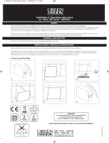
Page is loading ...

Part numbers:
Fixed:- VSWITCHC & VSWITCHF
It is recommended that luminaires are installed and fitted
by a qualified electrician ensuring the installation complies
to the current IET wiring regulation.
If replacing existing fitting, please ensure you follow these
instructions and the appropriate wiring regulations. This
product is designed for connection to a 230V AC Mains
supply.
Always switch off mains supply before servicing a fitting.
Special attention should be paid for any installations with
low ceiling voids.
This fitting is compatible with most leading and trailing
edge dimmers for best results use a dimmer designed for
LED drivers.
Please note that many dimmers have a minimum load
requirement which may mean multiple units have to be
connected for the dimmer to function correctly.
Please see GreenBrook website for compatible dimmers -
www.greenbrook.co.uk.
Do not stare directly in to the light fitting.
We recommend that a sample hole is cut in some scrap
material to familiarise yourself with the installation.
Once you are completely satisfied, locate the areas
suitable to install these luminaires. Cut a suitable round
hole in the ceiling 73mm and ensure there is sufficient
space in the ceiling void without infringing on joist, water
pipes or electrical cables.
Fit this product as illustrated. Connect this product to a
mains 230V supply only. Connect the Brown feed wire to
“L”, connect the Blue feed wire to “N”. Driver is class 1
and does require an earth connection. Also earth
connections are provided on the driver to maintain earth
circuit continuity.
Ensure cables are clamped in position and secured into
place with the supplied screw. See Dia.3.
Ensure there is adequate free air ventilation around the
fitting. The nearest illuminated surface must be at least
0.5m distance from the front of the fitting. Do not install
this product into new plaster or damp areas.
Stage 1 -
Read instructions and check
you have all the tools and
accessories to complete
installation correctly. These
luminaires are suitable for a
30, 60 or 90 minute fire rated
ceiling only.
Cut a suitable hole (73mm).
INSTALLATION INSTRUCTIONS
IMPORTANT INFORMATION
Installation Instructions for:-
‘Vela Switch’ Range
-LED 30, 60 & 90 Mins
Fire Rated Mains Voltage
Dimmable Downlights
Dia.1
Cut Out: 73mm
Stage 2 -
Wire as per installation instructions above . See Dia.2.
Dia.3
Dia.2
Vela Switch Ins Aug 18.qxp_LED FR 29/08/2018 10:51 Page 1

Issue no: 704962
WEST ROAD . HARLOW
ESSEX . CM20 2BG . UK
info@greenbrook.co.uk
www.greenbrook.co.uk
EMC
Additional Bezels:-
Fixed
ADVBEZG Gold
ADVBEZMB Matt Black
ADVBEZSC Satin Chrome
ADVBEZPC Polished Chrome
Rated Voltage: 230V~50Hz
Circuit Wattage: 7.5W
Ballast Type: LED driver
Class: I
CRI: >80
Operating Temperature: -20°C - +40°C
IP Rating (Front face): IP65
Hole Cut Out: 73mm
Life Span: 50,000 hours
Conforms To: Part B, C, E & L
VSWITCHC - Clear Diffuser
Beam Angle: 60°
Colour Temp: 3,000K
Luminaire Lumens Output: 580, 76 lm/W
Colour Temp: 4,000K
Luminaire Lumens Output: 610, 81 lm/W
VSWITCHF - Frosted Diffuser
Beam Angle: 95°
Colour Temp: 3,000K
Luminaire Lumens Output: 400, 52 lm/W
Colour Temp: 4,000K
Luminaire Lumens Output: 450, 62 lm/W
TECHNICAL INFORMATION
GUARANTEE
Your GreenBrook LED Fire Rated Downlight
is guaranteed for 3 years from the
date of purchase.
This is in addition to your statutory rights.
PLEASE KEEP THESE INSTRUCTIONS
SAFE FOR FUTURE REFERENCE
Dia.5 Dia.6
Air Circulation Information -
To prevent accidental damage to the luminaire and
to ensure good air flow around the fitting we
recommend the minimum clearances as shown.
A = 50 - 75mm
B = 25mm A
B
Stage 4 -
Press springs back and push luminaire body into aperture.
Connect wires as per instructions to fit.
Stage 3 -
To select the chosen colour temperature choice, move
the switch to either 3,000K or 4,000K. See Dia.4.
Selector switch for
3,000K or 4,000K
Dia.4
Vela Switch Ins Aug 18.qxp_LED FR 29/08/2018 10:51 Page 2
/


