
18-GAUGE 2-INCH
BRAD NAILER
Instruction Manual
IMPORTANT: Your new tool has been engineered and manufactured to WEN’s highest standards for dependability,
ease of operation, and operator safety. When properly cared for, this product will supply you years of rugged,
trouble-free performance. Pay close attention to the rules for safe operation, warnings, and cautions. If you use
your tool properly and for its intended purpose, you will enjoy years of safe, reliable service.
NEED HELP? CONTACT US!
Have product questions? Need technical support? Please feel free to contact us:
TECHSUPPOR[email protected]1-847-429-9263 (M-F 8AM-5PM CST)
For replacement parts and the most up-to-date instruction manuals, visit WENPRODUCTS.COM
MODEL 61721, 61723K

CONTENTS
WELCOME 3
Introduction ..................................................................................................... 3
Specifications ................................................................................................... 3
SAFETY 4
General Safety Rules ........................................................................................ 4
Brad Nailer Safety Warnings ............................................................................ 6
BEFORE OPERATING 7
Unpacking & Packing List .................................................................................7
Know Your Brad Nailer ..................................................................................... 7
Preparation & Adjustments .............................................................................. 8
OPERATION & MAINTENANCE 10
Operation ....................................................................................................... 10
Maintenance ....................................................................................................12
Troubleshooting Guide ................................................................................... 13
Exploded View & Parts List .............................................................................14
Warranty Statement ........................................................................................16
2
To purchase air compressors, air hoses, and other accessories, visit WENPRODUCTS.COM

SPECIFICATIONS
INTRODUCTION
Thanks for purchasing the WEN Brad Nailer. We know you are excited to put your tool to work, but first, please
take a moment to read through the manual. Safe operation of this tool requires that you read and understand this
operator’s manual and all the labels affixed to the tool. This manual provides information regarding potential safety
concerns, as well as helpful assembly and operating instructions for your tool.
NOTE: The following safety information is not meant to cover all possible conditions and situations that may occur.
WEN reserves the right to change this product and specifications at any time without prior notice.
At WEN, we are continuously improving our products. If you find that your tool does not exactly match this manual,
please visit wenproducts.com for the most up-to-date manual or contact our customer service at 1-847-429-9263.
Keep this manual available to all users during the entire life of the tool and review it frequently to maximize
safety for both yourself and others.
Indicates danger, warning, or caution. The safety symbols and the explanations with them deserve your
careful attention and understanding. Always follow the safety precautions to reduce the risk of fire, electric shock
or personal injury. However, please note that these instructions and warnings are not substitutes for proper ac-
cident prevention measures.
3
Model Number 61721, 61723K
Min. Operating Pressure 60 PSI
Max. Operating Pressure 115 PSI
Air Inlet 1/4" NPT
Nail Type 18-Gauge Brad Nails
Nail Length 3/8" to 2"
Magazine Capacity 100 Fasteners
Air Consumption (Cont.) 1.8 CFM at 80 PSI
Product Dimensions 10-1/8" x 10-3/4" x 2-5/8"
Product Weight 2.8 lbs

GENERAL SAFETY RULES
WORK AREA SAFETY
1. Keep work area clean and well lit. Cluttered or dark
areas invite accidents.
2. Do not operate power tools in explosive atmo-
spheres, such as in the presence of flammable liquids,
gases or dust. Power tools create sparks which may ig-
nite the dust or fumes.
3. Keep children and bystanders away while operating
a power tool. Distractions can cause you to lose control.
ELECTRICAL SAFETY
1. Power tool plugs must match the outlet. Never mod-
ify the plug in any way. Do not use any adapter plugs
with earthed (grounded) power tools. Unmodified plugs
and matching outlets will reduce risk of electric shock.
2. Avoid body contact with earthed or grounded surfac-
es such as pipes, radiators, ranges and refrigerators.
There is an increased risk of electric shock if your body
is earthed or grounded.
3. Do not expose power tools to rain or wet conditions.
Water entering a power tool will increase the risk of elec-
tric shock.
4. Do not abuse the cord. Never use the cord for car-
rying, pulling or unplugging the power tool. Keep cord
away from heat, oil, sharp edges or moving parts.
Damaged or entangled cords increase the risk of electric
shock.
5. When operating a power tool outdoors, use an ex-
tension cord suitable for outdoor use. Use of a cord
suitable for outdoor use reduces the risk of electric
shock.
6. If operating a power tool in a damp location is un-
avoidable, use a ground fault circuit interrupter (GFCI)
protected supply. Use of a GFCI reduces the risk of elec-
tric shock.
PERSONAL SAFETY
1. Stay alert, watch what you are doing and use com-
mon sense when operating a power tool. Do not use a
power tool while you are tired or under the influence
of drugs, alcohol or medication. A moment of inatten-
tion while operating power tools may result in serious
personal injury.
2. Use personal protective equipment. Always wear
eye protection. Protective equipment such as a respira-
tory mask, non-skid safety shoes and hearing protection
used for appropriate conditions will reduce the risk of
personal injury.
3. Prevent unintentional starting. Ensure the switch is
in the off-position before connecting to power source
and/or battery pack, picking up or carrying the tool.
Carrying power tools with your finger on the switch or
energizing power tools that have the switch on invites
accidents.
4. Remove any adjusting key or wrench before turning
the power tool on. A wrench or a key left attached to a
rotating part of the power tool may result in personal
injury.
5. Do not overreach. Keep proper footing and balance
at all times. This enables better control of the power
tool in unexpected situations.
6. Dress properly. Do not wear loose clothing or jew-
elry. Keep your hair and clothing away from moving
parts. Loose clothes, jewelry or long hair can be caught
in moving parts.
Safety is a combination of common sense, staying alert and knowing how your item works. The term “power tool”
in the warnings refers to your mains-operated (corded) power tool or battery-operated (cordless) power tool.
SAVE THESE SAFETY INSTRUCTIONS.
WARNING! Read all safety warnings and all instructions. Failure to follow the warnings and instructions may
result in electric shock, fire and/or serious injury.
4

GENERAL SAFETY RULES
7. If devices are provided for the connection of dust
extraction and collection facilities, ensure these are
connected and properly used. Use of dust collection
can reduce dust-related hazards.
POWER TOOL USE AND CARE
1. Do not force the power tool. Use the correct power
tool for your application. The correct power tool will
do the job better and safer at the rate for which it was
designed.
2. Do not use the power tool if the switch does not turn
it on and off. Any power tool that cannot be controlled
with the switch is dangerous and must be repaired.
3. Disconnect the plug from the power source and/or
the battery pack from the power tool before making
any adjustments, changing accessories, or storing
power tools. Such preventive safety measures reduce
the risk of starting the power tool accidentally.
4. Store idle power tools out of the reach of children
and do not allow persons unfamiliar with the power
tool or these instructions to operate the power tool.
Power tools are dangerous in the hands of untrained us-
ers.
5. Maintain power tools. Check for misalignment or
binding of moving parts, breakage of parts and any
other condition that may affect the power tool’s opera-
tion. If damaged, have the power tool repaired before
use. Many accidents are caused by poorly maintained
power tools.
6. Keep cutting tools sharp and clean. Properly main-
tained cutting tools with sharp cutting edges are less
likely to bind and are easier to control.
7. Use the power tool, accessories and tool bits, etc.
in accordance with these instructions, taking into ac-
count the working conditions and the work to be per-
formed. Use of the power tool for operations different
from those intended could result in a hazardous situa-
tion.
8. Use clamps to secure your workpiece to a stable
surface. Holding a workpiece by hand or using your
body to support it may lead to loss of control.
9. KEEP GUARDS IN PLACE and in working order.
SERVICE
1. Have your power tool serviced by a qualified repair
person using only identical replacement parts. This
will ensure that the safety of the power tool is main-
tained.
CALIFORNIA PROPOSITION 65 WARNING
Some dust created by power sanding, sawing, grinding,
drilling, and other construction activities may contain
chemicals, including lead, known to the State of Califor-
nia to cause cancer, birth defects, or other reproductive
harm. Wash hands after handling. Some examples of
these chemicals are:
• Lead from lead-based paints.
• Crystalline silica from bricks, cement, and other
masonry products.
• Arsenic and chromium from chemically treated
lumber.
Your risk from these exposures varies depending on
how often you do this type of work. To reduce your ex-
posure to these chemicals, work in a well-ventilated area
with approved safety equipment such as dust masks
specially designed to filter out microscopic particles.
5
Safety is a combination of common sense, staying alert and knowing how your item works. The term “power tool”
in the warnings refers to your mains-operated (corded) power tool or battery-operated (cordless) power tool.
SAVE THESE SAFETY INSTRUCTIONS.
WARNING! Read all safety warnings and all instructions. Failure to follow the warnings and instructions may
result in electric shock, fire and/or serious injury.

BRAD NAILER SAFETY WARNINGS
BRAD NAILER SAFETY
1. THIS TOOL IS DESIGNED for household use only, not
for industrial or professional purposes. Do not force the
tool to do a job for which it was not designed.
2. INSPECT TOOL BEFORE USE. Do not operate if any
portion of the tool, trigger, or safety bracket is damaged,
inoperable, disconnected, or altered. Leaking air,
damaged parts, or missing parts should be repaired or
replaced.
3. GRIP THE TOOL FIRMLY with both hands to maintain
control while still allowing it to recoil away from the work
surface as the fastener is driven.
4. KEEP FACE AND BODY PARTS AWAY from the back
of the tool cap when working in restricted areas. Sudden
recoil can result in impact to the body, especially when
nailing into hard or dense material.
5. DO NOT DISCHARGE fasteners into open air, concrete,
stone, extremely hard woods, knots or any material too
hard for the fastener to penetrate.
6. DO NOT DRIVE FASTENERS near the edge of your work
material. The workpiece may split, causing the fastener
to ricochet, injuring you or a bystander. Be aware that
the fastener may follow the grain of the wood, causing
it to protrude unexpectedly from the side of the work
material. Drive the fastener perpendicular to the grain to
reduce risk of injury.
7. DO NOT DRIVE FASTENERS onto the heads of other
fasteners. Do not use the tool at too steep of an angle.
Personal injury from strong recoil, jammed fasteners, or
ricochetted nails may result.
8. BE AWARE of material thickness when using the nailer.
A protruding nail may cause injury.
9. WHEN THE TOOL IS BEING UTILIZED AT PRESSURES
ON THE HIGH END of its operating range, fasteners can
be driven completely through thin or very soft work
material. Make sure the pressure in the compressor is
set so that fasteners are set into the material and not
pushed completely through.
10. REMOVE FINGER FROM TRIGGER when not driving
fasteners. Never carry the tool with your finger on the
trigger.
11. IF THE FASTENERS ARE JAMMED, disconnect
the tool from the air supply first before removing the
jammed fasteners.
12. DISCONNECT tool from air supply when not in use.
Remove fasteners from magazine before leaving the area
or passing the tool to another operator. Do not climb
ladders, stairs, scaffoldings, etc. without disconnecting
the tool. Do not carry a connected tool to another work
area. Do not make adjustments, remove magazine,
perform maintenance or clear jammed fasteners while
connected to the air supply.
13. DO NOT REMOVE, tamper with, or otherwise cause
the tool, trigger or safety bracket to become inoperable.
Do not tape or tie the trigger or safety bracket in the ON
position. Do not remove springs from the safety bracket.
Make daily inspections for free movement of the trigger
and safety bracket. Do not alter or modify the tool in any
way.
14. MAINTAIN TOOLS PROPERLY. Always keep tools
clean and in good working order. Follow instructions for
lubricating, changing accessories and storage.
WARNING! Do not let comfort or familiarity with the product replace strict adherence to product safety rules.
Failure to follow the safety instructions may result in serious personal injury.
6

7
UNPACKING
Carefully remove the brad nailer from the packaging and place it on a sturdy, flat surface. Make sure to take out all
contents and accessories. Do not discard the packaging until everything is removed. Check the packing list below
to make sure you have all of the parts and accessories. If any part is missing or broken, please contact customer
service at 1-847-429-9263 (M-F 8-5 CST), or email [email protected].
UNPACKING & PACKING LIST
61721 PACKING LIST
Description Quantity
Brad Nailer 1
3mm Hex Wrench 1
4mm Hex Wrench 1
Air Tool Oil 1
Manual 1
Description Quantity
Brad Nailer 1
3mm Hex Wrench 1
4mm Hex Wrench 1
Air Tool Oil 1
Manual 1
Case 1
18-Gauge 3/8-Inch Nails 500
18-Gauge 3/4-Inch Nails 500
18-Gauge 1-Inch Nails 500
18-Gauge 2-Inch Nails 500
61723K PACKING LIST
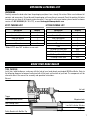
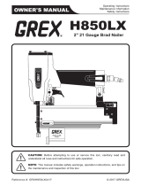
TOOL PURPOSE
Install trim, build birdhouses, and more with the help of your handy-dandy newfangled WEN Brad Nailer. Refer to
the following diagrams to become familiarized with all the parts and controls of your tool. The components will be
referred to later in the manual for assembly and operation instructions.
KNOW YOUR BRAD NAILER
Exhaust
Trigger
Depth Adjustment Wheel
Jam Clearing Latch
Safety Bracket with No-Mar Tip
Air Inlet
Magazine Lock
Low Nail Indicator Window
Magazine
*Model 61721 does NOT include a case or nails.

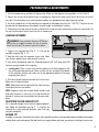
PREPARATIONS & ADJUSTMENTS
LUBRICATING THE TOOL
This tool requires lubrication before each use (especially the first use). If an inline oiler is used, manual lubrication
through the air inlet is not required. Proper lubrication is the owner’s responsibility. Failure to lubricate the tool
properly will dramatically shorten the life of the tool and void the warranty.
NOTE: The surface of the workpiece can be damaged by excessive lubrication.
1. Disconnect the tool from the air supply.
2. Turn the tool so the air inlet is facing up. Place 4 – 5 drops of air tool oil into the air inlet.
3. Connect the tool to the air supply as instructed below. Load fasteners as instructed below. Fire the tool 3 – 4 times
into a piece of scrap wood to lubricate the internal parts of the tool. Wipe off any excess oil from the exhaust cap
and the air inlet.
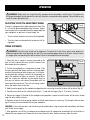
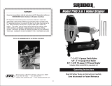
CONNECTING THE TOOL TO AN AIR SUPPLY
Your tool should be connected to a properly installed compressed air supply. The working pressure of the air com-
pressor must be regulated to fit the operating pressure of your nailer (60 – 100 PSI). Refer to (Fig. 1) for the recom-
mended accessories and connection configuration.
0
20
40
60 80 100
120
140
160
To Air Tool Quick Connector Quick Coupler
To Compressor
Regulator
Lubricator Filter
WARNING! Make sure the nailer magazine is empty and the tip of the nailer is pointed away from you when
connecting to the air supply. To reduce the risk of misfires, connect the air supply BEFORE loading fasteners.
Make sure the nailer magazine is empty when connecting the air supply. Never aim the tip of the nailer towards
yourself or others.
WARNING! Use only clean, dry, and regulated air. Do not use bottled gases to power this tool. There is a
risk of explosion, and serious personal injury may result. Do not operate when the air pressure is outside of the
recommended range (60 to 100 PSI).
Fig. 1
8

9
1. Turn the compressor on and allow it to pressurize. Make sure the tool pressure regulator is set to 0 (Fig. 2).
2. Connect the air hose to the outlet of your air compressor. Connect the other end of the air hose to the air inlet of
the nailer. The connections must click into place audibly. Use appropriate hose tape to prevent leaking.
3. On the air compressor, set the tool pressure regulator to the proper pressure (60 – 100 PSI). The pressure can
be adjusted later depending on firing depth, fastener length, and workpiece hardness.
4. To disconnect the tool from the air hose, pull back the ring on the quick connector to release the connection. Do
the same to disconnect the air hose from the air compressor.
PREPARATIONS & ADJUSTMENTS
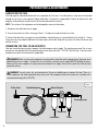
LOADING FASTENERS Fig. 2
2 1
1
Fig. 3
Fig. 4
1. Depress the magazine lock (Fig. 2 - 1). Pull out the
movable magazine (Fig. 2 - 2).
2. Hold the nailer with the magazine at your side. Make
sure the tip is pointed away from yourself or others.
WARNING! Always load the fasteners AFTER con-
necting the air supply to reduce the risk of misfires.
Never aim the tip of the nailer at yourself or others.
3. Your nailer is designed to work with 18-gauge brad nails 3/8” to 2” long. Up to 100
fasteners may be loaded in the magazine.
• Loading nails: Place a clip of nails into the grooves of the fixed magazine, with
the nail tips pointing downwards. Make sure the nail tips are against the bottom
of the magazine, and the nail heads rest on the appropriate groove of the fixed
magazine track (Fig. 3).
4. Push the movable magazine forward until it clicks shut.
Make sure it is locked in place.
NOTE: Some force may be required to fully close the mag-
azine when fasteners are loaded.
NOTE: Regularly check the fastener gauge window, and
load more fasteners as necessary. Dry-firing the tool can
damage it, and may leave unwanted marks on your work-
piece.
ADJUSTING THE AIR EXHAUST CAP
Air is released through the air exhaust cap during opera-
tion. Rotate the adjustable cap (Fig. 3 - 1) to direct the
released air in your preferred direction, away from you
and your workpiece.
NO-MAR TIP
A rubber no-mar tip is attached to your tool’s safety bracket to reduce marring and damage to workpiece during op-
eration. Make sure to disconnect the tool from the air supply before adjusting, removing or installing the no-mar tip.

10
OPERATION
WARNING! Before each use, check the nailer, compressed air connections, and air lines. If any parts are
missing or damaged, do not operate this tool until the parts are repaired and/or replaced. Failure to do so may
result in serious personal injury.
ADJUSTING THE DEPTH-ADJUSTMENT WHEEL
The tool is equipped with a depth-adjustment wheel (Fig.
5 - 1) to set the penetration depth of the fasteners. Experi-
ment on a piece of scrap wood to find the proper depth for
your workpiece, air pressure, fastener length, etc.
• Turn the wheel clockwise to increase the firing depth.
• Turn the wheel counterclockwise to decrease the fir-
ing depth.
1
WARNING! Using this type of tool can be dangerous. To reduce the risk of injury, always wear proper eye
and hearing protection when operating this tool. Stay alert and keep proper balance at all times. Always release
the trigger when not operating the tool to reduce the risk of unintended fastener discharge.
FIRING FASTENERS
1. Check that the air supply is securely connected to the
tool, set to the correct pressure, and the fasteners have
been loaded into the magazine.
2. Test the driving depth on a scrap piece of wood. If the
fasteners penetrate too deeply, decrease the firing depth,
or adjust the regulator to lower air pressure. If the fasten-
ers penetrate too shallowly, increase the firing depth, or
adjust the regulator to higher air pressure. Try to adjust
both the air pressure regulator and the depth wheel so
that you can achieve your desired firing depth with the
lowest possible air pressure. This will save energy, reduce
noise, and reduce wear on the tool.
3. Hold the nailer upright on the workpiece and position the no-mar tip where the fastener will be driven (Fig. 6).
4. Carefully press down on the safety bracket (Fig. 6 - 1) and pull the trigger (Fig. 6 - 2) to drive a fastener.
5. Release the trigger, lift the tool off the workpiece and reposition it where the next fastener will be driven. Repeat
step 4 to drive another fastener.
6. Regularly check the fastener gauge window, and load more fasteners as necessary. Dry-firing the tool can dam-
age it, and may leave unwanted marks on your workpiece.
WARNING: If the safety bracket is not functioning as described above, stop using the tool immediately and discon-
nect it from the air supply.
7. After operation, turn off the air compressor and depressurize the compressor according to the instructions in-
cluded with your compressor. Disconnect the air hose from the nailer. Remove fasteners from the nailer.
90°
1
2
Fig. 5
Fig. 6

11
OPERATION
DRIVING MODES
Your nailer has two driving modes: single-sequential and bump-fire. For details, see below.
Single-sequential:
1. Press the safety bracket against the workpiece.
2. Pull the trigger. A fastener is fired.
3. Remove the safety bracket from the workpiece. Re-position the tool. Repeat steps 1 – 3.
Bump-fire:
1. Pull the trigger.
2. Press the safety bracket against the workpiece. A fastener is fired.
3. Remove the safety backet from the workpiece. Re-position the tool. Repeat steps 1 - 3.
CLEARING JAMMED FASTENERS
WARNING! Disconnect air line from the tool and remove all other fasteners before removing jammed fasten-
ers, in order to avoid personal injury. Keep the tool pointed away from yourself and others.
1. Disconnect the tool from the air supply. Open the magazine and remove all other fasteners from the magazine.
2. Flip open the jam-clearing latch, and pull up to open the front plate. Remove the jammed fastener, using pliers or
another tool if necessary.
3. If the piston assembly is in the down position, insert a screwdriver or other rod into the nosepiece and push the
piston back in position.
4. Close the front plate. Push down latch cover to secure the front plate to the nosepiece. Make sure the trigger and
safety bracket move freely without sticking or binding.
5. Connect the nailer to the air supply. Load fasteners. Test-fire the nailer into a piece of scrap wood to make sure
it is operating properly.

MAINTENANCE
WARNING! Disconnect tool from air supply and empty fasteners from the magazine before performing any
cleaning or maintenance.
LUBRICATION
Routine lubrication of the tool is required for best performance. If the tool is used without an in-line oiler, place 3 – 4
drops of pneumatic tool oil into the air inlet of the tool at the beginning of each workday. This will ensure the moving
components, seals, and O-rings are properly lubricated.
COMPRESSOR
Follow the maintenance schedule recommended in your air compressor’s owner’s manual. Regularly check the air
filter and drain the tank at least weekly. This will help keep water and other contaminants from entering your nailer.
CLEANING
Keep tools clean for better and safer performance. Wipe the tool clean with a damp towel and mild soap. Blow the
tool clean using compressed air, then use non-flammable cleaning solutions to wipe exterior of the tool as neces-
sary. Do not soak tool with cleaning solutions. Such solutions can damage internal parts.
INSPECTION
1. Inspect trigger and safety mechanism to assure system is complete and functional (no loose or missing parts,
no binding or sticking parts). Do not operate if any portion of the tool, trigger, or safety bracket is damaged,
inoperable, disconnected, or altered. Leaking air, damaged parts, or missing parts should be repaired or replaced
before use.
2. Keep all screws tight. Loose screws can cause personal injury or damage the tool.
3. Dirt, water, and other contaminants in the air supply are major causes of pneumatic tool wear. Follow the com-
pressor instructions to check the compressor’s air filter and to drain the compressor’s tank regularly.
STORAGE
Place the tool and accessories inside the blow mold case to protect it from dust and moisture. Store the unit and
accessories in a dark, dry, frost-free and well ventilated place, out of the reach of children. The ideal storage tem-
perature is between 50 to 86 °F (10 and 30 °C).
PRODUCT DISPOSAL
Used pneumatic tools contain recyclable materials and should not be disposed with household waste. Please take
this product to your local recycling facility for responsible disposal and to minimize its environmental impact.
12

13
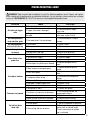
PROBLEM CAUSE SOLUTION
Air leaking at trigger
area
1. O-ring in trigger valve is damaged. 1. Check and replace O-ring.
2. Trigger valve head is damaged. 2. Check and replace trigger
valve head.
3. Trigger valve stem, seal or O-ring is
damaged.
3. Check and replace trigger
valve stem, seal or O-ring.
Air leaking between
body and drive guide 1. Damaged piston O-ring or bumper. 1. Check and replace O-ring or
bumper.
Air leaking between
body and cylinder cap
1. Screw loose. 1. Tighten screws.
2. Damaged gasket. 2. Check and replace seal.
Blade driving fastener
too deeply
1. Worn bumper. 1. Replace bumper.
2. Air pressure is too high. 2. Adjust the air pressure.
Runs slowly or has
power loss
1. Insufficient oil. 1. Lubricate as instructed.
2. Insufficient air supply. 2. Check air supply.
3. Broken spring in cylinder cap. 3. Replace spring.
4. Exhaust port in cylinder cap is blocked. 4. Replace damaged internal
parts.
Tool skips a fastener
1. Worn bumper or damaged spring. 1. Replace bumper or pusher
spring.
2. Dirt in drive guide. 2. Clean drive channel of front
plate.
3. Inadequate airflow to tool. 3. Check hose and compressor
fittings.
4. Worn or dry O-ring on piston. 4. Replace O-ring or lubricate.
5. Damaged O-ring on trigger valve. 5. Replace O-ring.
6. Cylinder cap seal leaking. 6. Replace seal.
Fasteners are jammed
1. Joint guider is worn. 1. Replace joint guider.
2. Fasteners are wrong size or damaged. 2. Use the recommended and
undamaged fasteners.
3. Magazine or front plate screws are loose. 3. Tighten screws.
4. Blade in piston assembly is damaged. 4. Replace piston assembly.
Tool will not drive
down tight
1. Worn blade in piston assembly. 1. Replace piston assembly.
2. Lack of power. 2 . Ad just to adequate air pressure.
3. Slow cycling and loss of power.
3. Check cylinder cap spring for
broken coils or reduced length.
Check if exhaust port of cylinder
cap is restricted.
TROUBLESHOOTING GUIDE
WARNING! Stop using the tool immediately if any of the following problems occur. Repairs and replace-
ments should only be performed by an authorized technician. For any questions, please contact our customer
service at 1-847-429-9263, M-F 8-5 CST or email us at [email protected].

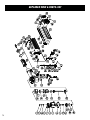
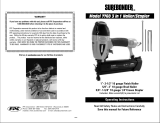
EXPLODED VIEW & PARTS LIST
14

15
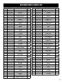
EXPLODED VIEW & PARTS LIST
No. Part No. Description Qty.
1 61720-001 Screw 1
2 61720-002 Bushing 1
3 61720-004 Washer 1
4 61721-004 Bushing Washer 1
5 61721-005 Screw 1
6 61721-006 Washer 1
7 61721-007 Cylinder Cap 1
8 61721-008 Gasket 1
9 61720-010 Seal 1
10 61721-010 Spring 1
11 61720-015 Valve 1
12 61720-012 O-Ring 1
13 61720-013 O-Ring 1
14 61720-014 O-Ring 1
15 61720-016 Stop Washer 1
16 61720-018 Collar 1
17 61720-017 O-Ring 1
18 61721-018 Cylinder 1
19 61720-021 O-Ring 1
20 61721-020 O-Ring 1
21 61720-019 O-Ring 1
22 61721-022 Piston Assembly 1
23 61721-023 Bumper 1
24 61721-024 Body 1
25 61720-025 Seal 1
26 61721-026 Safe Guide 1
27 61720-031 Spring Pin 1
28 61721-028 Spring 1
29 61721-029 Safety Bracket A 1
30 61721-030 Safety Bracket B 1
31 61721-031 Bushing 1
32 61721-032 Washer 1
33 61720-061 Screw 1
34 61721-034 Rubber Cover 1
35 61720-032 O-Ring 1
36 61720-033 Trigger Valve Head 1
37 61720-034 Spring 1
38 61720-035 O-Ring 1
39 61721-039 Trigger Valve Stem 1
No. Part No. Description Qty.
40 61720-038 Trigger Valve Guide 1
41 61720-037 O-Ring 1
42 61721-042 Spring 1
43 61720-044 Washer 1
44 61721-044 Trigger Assembly 1
45 61720-042 Trigger Pin 1
46 61721-046 Latch Assembly 1
47 61721-047 Latch Cover 1
48 61721-048 Pin 1
49 61721-049 Plate 1
50 61721-050 Pin 1
51 61721-051 Rail 1
52 61720-046 Screw 1
53 61721-053 Front Plate 1
54 61721-054 Drive Guide 1
55 61721-055 Fixed Magazine 1
56 61721-056 Feeder Shoe 1
57 61721-057 Feeder Set 1
58 61720-059 Spring 1
59 61721-059 Movable Magazine 1
60 61721-060 Stop Plate 1
61 61720-068 Screw 1
62 61721-062 Screw 1
63 61721-063 Joint Guide 1
64 61721-064 Bushing 1
65 61721-065 Spring 1
66 61721-066 Lock 1
67 61721-067 Nut 1
68 61721-068 Washer 1
69 61721-069 Screw 1
70 61721-070 Screw 1
71 61721-071 Support 1
72 61721-072 Nut 1
73 61721-073 Soft Grip Sleeve 1
74 61720-070 O-Ring 1
75 61721-075 End Cap 1
76 61720-072 Air Plug 1

WARRANTY STATEMENT
V. 2023.11.14
16
WEN Products is committed to building tools that are dependable for years. Our warranties are consistent with this
commitment and our dedication to qualit
y.
LIMITED WARRANTY OF WEN PRODUCTS FOR HOME USE
GRE
AT LAKES TECHNOLOGIES, LLC (“Seller”) warrants to the original purchaser only, that all WEN
consumer
power tools will be free from defects in material or workmanship during personal use for a period of two (2) years
used
for professional or commercial use. Purchaser has 30 days from the date of purchase to report missing or
damaged parts.
SELLER’S
SOLE OBLIGATION AND YOUR EXCLUSIVE REMEDY under this Limited Warranty and, to the extent per-
mitted
by law, any warranty or condition implied by law, shall be the replacement of parts, without charge, which a
re
defective
in material or workmanship and which have not been subjected to misuse, alteration, careless handling,
misrepai
r, abuse, neglect, normal wear and tear,
improper maintenance, or other conditions adversely affecting the
Product
or the component of the Product, whether by accident or intentionally, by persons other than Seller. To
make
a claim under this Limited Warranty, you must make sure to keep a copy of your proof of purchase that
clearly
-
dor
of Great Lakes Technologies, LLC. Purchasing through third party vendors, including but not limited to garage
sales,
pawn shops, resale shops, or any other secondhand merchant, voids the warranty included with this
product.
Contact [email protected] or 1-800-232-1195 with the following information to make arrangements:
your
shipping address, phone number, serial number, required part numbers, and proof of purchase. Damaged
or
defective parts and products may need to be sent to WEN before the replacements can be shipped out.
-
turning
a product for warranty service, the shipping charges must be prepaid by the purchaser. The product
must
be
shipped in its original container (or an equivalent), properly packed to withstand the hazards of shipment. The
product
must be fully insured with a copy of the proof of purchase enclosed. There must also be a description of
the
will be returned and shipped back to the pur
chaser at no charge for addresses within the contiguous United States.
THIS
LIMITED WARRANTY DOES NOT APPLY TO ITEMS THAT WEAR OUT FROM REGULAR USAGE OVER TIME,
INCLUDING
BELTS, BRUSHES, BLADES, BATTERIES, ETC. ANY IMPLIED WARRANTIES SHALL BE LIMITED IN
DUR
ATION TO TWO (2) YEARS FROM DATE OF PURCHASE. SOME STATES IN THE U.S. AND SOME CANADIAN
PROVINCES
DO NOT ALLOW LIMITATIONS ON HOW LONG AN IMPLIED WARRANTY LASTS, SO THE ABOVE LIMI-
TAT
ION MAY NOT APPLY TO YOU.
IN
NO EVENT SHALL SELLER BE LIABLE FOR ANY INCIDENTAL OR CONSEQUENTIAL DAMAGES (INCLUDING
BUT
NOT LIMITED TO LIABILITY FOR LOSS OF PROFITS) ARISING FROM THE SALE OR USE OF THIS PRODUCT.
SOME ST
ATES IN THE U.S. AND SOME CANADIAN PROVINCES DO NOT ALLOW THE EXCLUSION OR LIMITAT
ION
OF
INCIDENTAL OR CONSEQUENTIAL DAMAGES, SO THE ABOVE LIMITATION OR EXCLUSION MAY NOT APPLY
TO YOU.
THIS
LIMITED WARRANTY GIVES YOU SPECIFIC LEGAL RIGHTS, AND YOU MAY ALSO HAVE OTHER RIGHTS
WHICH
VARY FROM STATE TO STATE IN THE U.S., PROVINCE TO PROVINCE IN CANADA AND FROM COUNTRY
TO COUNT
RY.
THIS
LIMITED WARRANTY APPLIES ONLY TO ITEMS SOLD WITHIN THE UNITED STATES OF AMERICA, CANA-
DA
AND THE COMMONWEALTH OF PUERTO RICO. FOR WARRANTY COVERAGE WITHIN OTHER
COUNTRIES,
CONT
ACT THE WEN CUSTOMER SUPPORT LINE. FOR WARRANTY PARTS OR PRODUCTS REPAIRED UNDER
W
ARRANTY SHIPPING TO ADDRESSES OUTSIDE OF THE CONTIGUOUS UNITED STATES, ADDITIONAL
SHIPPING
CHARGES MAY APPLY.
-
 1
1
-
 2
2
-
 3
3
-
 4
4
-
 5
5
-
 6
6
-
 7
7
-
 8
8
-
 9
9
-
 10
10
-
 11
11
-
 12
12
-
 13
13
-
 14
14
-
 15
15
-
 16
16


Ask a question and I''ll find the answer in the document
Finding information in a document is now easier with AI
Related papers
Other documents
-
Global Machinery Company ATBR1650-3PK User manual
-
 Grex 1850GB User manual
-
 Grex H850LX User guide
-
 Surebonder 7760 Installation guide
-
 Surebonder 7760 Owner's manual
-
Husky H125BN User manual
-
 Fini PRO63PAK User guide
-
Central Pneumatic 61694 Owner's manual
-
PowerSmart PS6130 User manual
-


