Page is loading ...

HDZON
INSTRUCTION
MANUAL
DT-570
SOLDERING
IRON
CHECKER
Thank
you
for
purchasing
the
HOZAN
DT-570
SOLDERING
IRON
CHECKER.
With
proper
care
and
handling,
this
fine
instrument
will
provide
years
of
trouble-free
operation.
Please
read
this
entire
instruction
manual
carefully
before
attempting
to
place
this
instrument
in
service.
Please
keep
this
instruction
manual
available
for
reference.
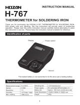
Identification
of
parts
and
contents
Power
switch
selector
Q
:
Ground
resistance
measurement
mV
:
し
eakage
current
voltage
measurement
Battery
lamp
Sensor
plate
Displ
Jack
The
battery
is
not
warranted
in
its
life
since
just
a
testing
battery.
Utilize
this
device
to
check
soldering
irons
1
condition
and
keep
it
good
always
through
measuring
leakage
current
voltage
and
ground
resistance
of
them.
This
is
applied
exclusively
to
soldering
irons
which
have
grounding
circuits.
Accessories
■2-pin
conversion
/
/\
adapter
X
/
\
9V
Laminated
(6F22)
battery
Specifications
し
eakage
voltage
Ground
resistance
Resolution
Measurement
range
Accuracy
Resolution
Measurement
range
Accuracy
Max.
readout
Sampling
rate
Power
supply
Battery
life
0.1
mV
Oto
199.9
mV
士
(5%rdg
+
1
dgt)
0.1
〇
0.1
to
199.9
Q
土
(5%rdg
+
1
dgt)
199.9
count
(Burnout:
1)
________________________
2
times/sec.
9V
Laminated
(6F22)
battery
x
1
Approx.
20
hours
(continuous
use)
(with
a
“
low
voltage
”
warning)
External
dimensions
71
(W)
x
31(H)
x
125(D)
mm
(not
including
the
protruding
part)
300g
Weight
1

Warning
and
caution
symbols
These
symbols
are
used
throughout
the
instruction
manual
to
alert
the
user
to
potential
safety
hazards
as
follows
:
Notice
when
incorrect
handling
could
cause
the
user's
death
or
serious
injury.
ICautioni
…
Notice
when
incorrect
handling
could
cause
injury
to
the
user
or
material
damage.
Even
if
the
instructions
do
not
have
|
ACautior^
mark,
there
are
some
possibilities
for
a
Precautions
--------------------------------------------
A
Caution
-----------------------------------------------
\
1.
The
sensor
plate
is
extremely
sensitive
to
shock.
Do
not
press
the
tip
of
the
soldering
iron
unnecessarily
against
the
sensor
plate
when
measuring.
2.
Precise
measurement
can
not
be
performed
if
the
sensor
plate
fixing
screws
are
loose.
Make
sure
that
the
sensor
plate
is
fixed
securely
prior
to
use.
Preparation
1
Load
a
battery.
Open
the
lid
of
the
battery
compartment
located
on
the
bottom
of
the
unit.
When
remove
the
lid,
binding
with
the
body
and
the
front
panel
could
be
loosened
together,
but
they
will
not
fall
apart
unless
loosen
the
other
screws.
Use
a
Phillips
screwdriver
No.1.
,
Connect
a
6F22
battery
to
the
terminals
correctly.
Return
the
lid
to
its
former
state.
2

Preparation
2
Soldering
irons
which
have
no
grounding
circuits
are
not
applicable.
Connecting
When
soldering
irons
which
have
power
plugs
type
A
(illustration
A
above)
:
Connect
the
power
plug
of
the
soldering
iron
to
be
measured
to
the
2-pin
adapter
provided,
and
connect
the
2-pin
adapter
5
to
the
wall
outlet.
--------
:
When
soldering
irons
which
have
power
plug
type
B
or
C
(illustration
B
or
C
above)
:
Connect
similarly
as
when
plugs
type
A
after
connect
ing
the
soldering
iron's
ground
terminal
and
the
2-pin
adapter
’
s
cavity
using
an
alligator
clip
and
such.
3
If
the
soldering
iron
to
be
measured
has
temperature
control
function,
set
it
to
maximum
temperature.
Operation
Connect
the
plug
of
one
side
of
the
ground
cord
with
plug
provided
to
the
jack
on
the
top
of
the
unit.
2
Select
the
desired
mode,
mV
(leakage
current
voltage
measurement)
or
Q(ground
resistance
measurement),
by
mode
selector.
Depress
the
power
switch.
Be
sure
that
the
BATTERY
lamp
does
not
illuminate.
If
it
illuminates
or
the
display
shows
no
letters,
change
the
battery
to
a
new
one.
4
Apply
the
plug
of
the
other
side
of
the
ground
cord
with
plug
connected
with
the
jack
to
the
sensor
plate.
The
numbers
indicated
on
the
display
will
get
closer
to
lower
value
gradually
and
be
stable.
Record
that
value.
When
mV
mode,
let
the
read
value...
[VJ
When
Q
mode,
let
the
read
value...
[RJ
These
values
are
the
basic
points
of
your
using
environment.
If
the
ground
cord
with
plug
is
not
connected,
strange
numbers
will
displayed.
But
this
in
not
malfunction.
3

Operation
5
6
7
8
9
Connect
the
plug
of
the
ground
cord
with
plug
which
is
connected
with
the
DT-570
to
the
socket
of
the
2-pin
adapter.
Turn
on
the
soldering
iron
and
wait
until
the
tip
is
heated.
Then
tin
the
tip
with
a
mall
amount
of
solder.
Apply
the
soldering
iron
’
s
tip
to
the
center
of
the
sensor
plate
and
heat
the
solder
on
the
sensor
plate
until
it
is
melted
enough.
Wait
until
the
displayed
value
is
stable,
and
record
it.
Read
the
value
when
the
temperature
of
the
soldering
iron
reaches
the
highest
temperature;
read
while
heating
enough
if
the
soldering
iron
has
no
temperature
control
function.
When
mV
mode,
let
the
read
value...
[V
2
]
When
Q
mode,
let
the
read
value...
[R
2
]
Find
the
leakage
current
voltage
(V)
and
the
ground
resistance
(R)
through
the
formula
below.
Leakage
current
voltage
V=V2-V1
(unit
:
mV)
Ground
resistance
R=R2-R1
(unit
:
Q)
Maintenance
and
Calibration
・
The
sensor
plate
is
a
consumable.
Replace
when
the
value
becomes
large.
[Replacement
part
:
DT-570-
1
Sensor
plate]
・
The
sensor
plate
will
be
worn
using
rather
lead-free
solder
than
lead
solder.
■
Wipe
gently
flux
and
such
stuck
on
the
painted
surface
of
the
unit
using
alcohol.
Do
not
use
thinner,
naphtha
or
such.
■
We
attach
a
calibration
certificate
to
DT-570-TA.
Please
ask
HOZAN
through
your
deal
er
to
re-calibrate
after
using
a
definite
period.
Refer
to
your
dealer
for
that
expense
and
details.
HOZAN
TOOL
INDUSTRIAL
CO.
LTD.
1-2-12
Saiwaicho,
Naniwa-ku,
Osaka
556-0021,
Japan
https://www.hozan.co.jP/E/
E-mail
:
th@hozan.co.jp
4
23.08
/