Dometic Caravan Roof Mount AC_Heat Pump_Model B3200-B3300_Type 3253.336-B3351.531-3254.341 Installation guide
- Category
- Split-system air conditioners
- Type
- Installation guide

1
REVISION:
Form No. 3311156.057 8/08
(Replaces 3311156.040)
©2008 Dometic, LLC
LaGrange, IN 46761
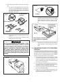
INSTALLATION
INSTRUCTIONS
Important: These Instructions
must stay with unit.
Owner read carefully.
This manual must be read and
understood before installation,
adjustment, service, or mainte-
nance is performed. This unit must
be installed by a qualifi ed service
technician. Modification of this
product can be extremely hazard-
ous and could result in personal
injury or property damage.
SERVICE OFFICE
Dometic, LLC
For Information
Contact:
www.dometic.com
CARAVAN ROOF MOUNT
AIR CONDITIONER
HEAT PUMP
MODELS B3200 OR B3300
used with one of the following:
3105007 Return Air Cover
3105935 Quick Cool Return Air Cover
and one of the following:
3310086 Analog Relay Kit Cool, Furnace, Heat Strip
3310137 Analog Relay Kit, Cool, Furnace, Heat Pump
This Unit Is Designed For Installation By
Original Equipment Manufacturers ONLY.
All Initial Installations Must Be Approved By Dometic
TYPE
3253.336
B3351.531
AIR CONDITIONER
3254.341
HEAT PUMP
RECORD THIS UNIT INFORMATION FOR
FUTURE REFERENCE:
Type Number
Product Number
Serial Number
Control Number
Control Serial Number
Date Purchased

2
SAFETY INSTRUCTIONS
This manual has safety information and instruc-
tions to help users eliminate or reduce the risk
of accidents and injuries.
RECOGNIZE SAFETY INFORMATION
This is the safety-alert symbol. When you see this
symbol in this manual, be alert to the potential
for personal injury.
Follow recommended precautions and safe op-
erating instructions.
UNDERSTAND SIGNAL WORDS
A signal word , WARNING OR CAUTION is used
with the safety-alert symbol. They give the level
of risk for potential injury.
indicates a potentially hazard-
ous situation which, if not avoided, could result
in death or serious injury.
indicates a potentially hazard-
ous situation which, if not avoided, may result in
minor or moderate injury.
used without the safety alert
symbol indicates, a potentially hazardous situa-
tion which, if not avoided, may result in property
damage.
Read and follow all safety information and in-
structions.
A. Product features or specifi cations as described or il-
lustrated are subject to change without notice.
The following are the basic requirements:
1. Installation opening. Cut through the roof and ceil-
ing.
2. Additional Wiring.
220-240 VAC, 50 Hz. 10 Amp.
3. Power with the air conditioner/heat pump on must
be above 209 VAC and the frequency must be at
50 HZ. at all times.
B. This air conditioner/heat pump Is designed for:
1. Installation on a caravan during the time
the vehicle is manufactured.
2. Mounting on the roof of a caravan.
3. Roof construction with rafters/joists on minimum
of 40.6 cm centers.
4. Minimum of 5 cm and maximum of 10 cm distance
between roof to ceiling of caravan.
C. The ability of the air conditioner/heat pump to maintain
the desired inside temperature depends on the heat
gain of the caravan.
Some preventative measures taken by the occupants of
the caravan can reduce the heat gain and improve the
performance of the air conditioner/heat pump. During
extremely high outdoor temperatures, the heat gain of
the vehicle may be reduced by:
1. Parking the caravan in a shaded area
2. Using window shades (blinds and/or curtains)
3. Keeping windows and doors shut or minimizing
usage
4. Avoiding the use of heat producing appliances
Operation on high fan/cooling mode will give optimum
or maximum effi ciency in high humidity or high outside
temperatures.
Starting the air conditioner/heat pump early in the
morning and giving it a "head start" on the expected
high outdoor ambient will greatly improve its ability to
maintain the desired indoor temperature.
For a more permanent solution to high heat gain, ac-
cessories like Dometic A&E outdoor patio and window
awnings will reduce heat gain by removing the direct
sun. They also add a nice area to enjoy company dur-
ing the cool of the evening.
D. Condensation
Note: The manufacturer of this air conditioner/heat pump
will not be responsible for damage caused by condensed
moisture on ceilings or other surfaces. Air contains mois-
ture and this moisture tends to condense on cold surfaces.
When air enters the caravan, condensed moisture may
appear on the ceiling, windows, metal parts, etc. The air
conditioner/heat pump removes this moisture from the
air during normal operation. Keeping doors and windows
closed when this air conditioner/heat pump is in operation
will minimize condensed moisture on cold surfaces.
1. GENERAL INFORMATION

3
The Manufacturer gives only general guidelines for Generator require-
ments. These generator requirements come from experiences consumers
have with our equipment in fi eld applications. When sizing generators, the
total electrical power consumption of the caravan must be considered.
Keep in mind that generators lose power because of altitude increase
above sea level, high outside temperatures and lack of maintenance.
2. INSTALLATION INSTRUCTIONS
A. PRECAUTIONS
Improper installation may damage equipment/
could endanger life, cause serious injury and/
or property damage.
B. CHOOSING PROPER LOCATION FOR THE
AIR CONDITIONER/HEAT PUMP
1 This air conditioner/heat pump is specifi cally
designed for installation on the roof of a caravan.
When determining your cooling requirements, the
following should be considered:
a. Size of caravan.
b. Window area (increases heat gain).
c. Amount of insulation in walls and roof;
d. Geographical location where the caravan will
be used.
e. Personal comfort level required.
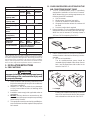
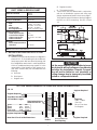
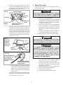
2. Normal Location-The air conditioner/heat pump is
designed to fi t over an existing roof vent opening.
When the vent is removed, it normally creates a
36.2 cm x 36.2 cm opening. See FIG. 1.
1. Read installation and operating instructions care-
fully before attempting to start your air conditioner/
heat pump installation.
2. Dometic, LLC will not be liable for any damages
or injury incurred due to failure in following these
instructions.
3. Installation must comply with applicable codes or
regulations.
4. DO NOT add any devices or accessories to this
air conditioner/heat pump except those specifi cally
authorized by Dometic.
5. This equipment must be serviced by qualifi ed per-
sonnel and some localities require these people to
be licensed.
FIG. 1
1/2L LL
1/3L
2/3L
FIG. 2
L = Length
3. Other Locations-When no roof vent is available or
another location is desired, the following is recom-
mended:
a. For one unit installation :
The air conditioner/heat pump should be
mounted slightly forward of the center (front to
back ) and centered from side to side on the
caravan. See FIG. 2.
b. For two unit installations:
Install one air conditioner/heat pump 1/3 and the
other 2/3's back from the front of the caravan
and centered from side to side. See FIG. 2.
SPECIFICATIONS
Type 3253.336 3254.341 B3351.531
Air Cond Heat
Pump Air Cond
Nominal Cooling
Capacity (KW) 3.2 3.2 3.2
Electrical Heat
Capacity (KW) 1.6 ---- 1.6
Electrical Rating 220 - 240 VAC 50 Hz. 1Ph.
FL Amps (Comp/
Motor) 5.2/1.1 5.2/1.1 5.3/0.9
LR Amps (Comp/
Motor) 26/3.8 26/3.8 22/4.4
Power (KW)
(Comp/Motor) 1.3 1.3 1.3
Power (KW)
(Heater) 1.5 ---- 1.5
Refrigerant
Grams/Oz. R407
496/17.5 R407
595/21.0 R22
510/18.0
Circuit Protection 10 Amp Time Delay Fuse
10 Amp Circuit Breaker
Generator Size 1 Unit 3.5 KW
2 Units 5.0 KW

4
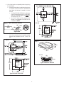
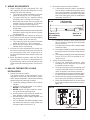
4. Check the location acceptability before beginning
the installation.
a. If possible mount the air conditioner/heat pump
in a section of the roof which is both fl at and
level when the caravan is parked on a level
surface
• On Type 3253.336 & 3254.341 a sideways
pitch or forward pitch up to 8° can be toler-
ated, but a backward pitch can never be
accepted. See FIG. 3.
• Up to a 15° slant to either side or front-
to-back is acceptable on B3351.531 air
conditioners ONLY.
b. Check on the roof to insure no obstructions
are in the area where the air conditioner/heat
pump will be installed. See FIG. 4, 4A, 5 &
5A.
FIG. 3 OK
Side Side
Good
8° With A/C Fac-
ing Forward
Types 3254.341 & 3253.336 FIG. 4A
Type B3351
FIG. 5
24 cm
73 cm
99 cm
43
cm
1.5 cm
43 cm
Types 3254.341 & 3253.336
FIG. 4
Types 3254.341 & 3253.336

5
Roof /Return Air Grill - Cross
Section
Light
36.2 cm
Prohibits Installation
Cabinet - Prohibits Use
FIG. 6
c. Check inside the caravan for return air cover
obstructions (i.e. door openings, room dividers,
curtains, ceiling fi xtures, etc.) See FIG. 6.
d. The roof must be designed to support 60 Kg.
when the caravan is in motion. Normally a 90
Kg. static load design will meet this require-
ment. See FIG. 7.
C. ROOF PREPARATIONS
The 36.2 cm x 36.2 cm opening is part of the return
air system of the air conditioner/heat pump and must
be fi nished in accordance with any national or local
codes.
1. Roof Vent Locations:
a. Remove all screws that secure the vent to the
roof and remove the vent from the opening.
b. Remove all sealing compound from around
the vent opening.
c. Seal all screw holes and all roof seams with a
quality all weather sealant. See FIG. 8.
FIG. 5A
Type B3351.531
43
cm
1.5 cm
43 cm
87 cm
32.5 cm
75 cm
FIG. 7 Force While Moving
Weight of A/C/HP Plus Service Personnel
d. If the opening is less than 36.2 cm x 36.2 cm,
it must be enlarged.
e. If the opening exceeds 36.5 cm x 36.5 cm, it
will be necessary to install spacers.
There may be electrical wiring between the
roof and the ceiling. Disconnect 220 - 240 volt
AC power cord and the positive (+) 12 volt DC
terminal at the supply battery. Failure to follow
this instruction may create a shock hazard
causing death or severe personal injury.
Seal All
Holes
And
Seams
Scrape
Sealant
Remove Screws & Remove VentFIG. 8

6
FIG. 12
2 cm 38 cm Min Wire
Length At Front
Of Opening
Frame Opening To Prevent Roof
collapse When Unit Tightened
Down
2. New Opening (installation other than vent open-
ing)
a. If a roof vent opening will not be used a 36.2
cm x 36.2 cm opening must be cut through the
roof and ceiling of the caravan. This opening
must be located between the roof reinforcing
members. See FIG. 9.
FIG. 9 Do Not Remove
Structure
No Blockages
Good
Depends On
Structure
d. The opening created must be framed to provide
adequate support and prevent air from being
drawn from the roof cavity. Lumber 2 cm or
more in thickness must be used. See FIG.
12.
FIG. 11
Cut Hole
Do Not Cut Electrical
Wires
FIG. 10
b. Mark a 36.2 cm x 36.2 cm square on the roof
and carefully cut the opening. See. FIG. 10,
11 & 12.
c. Using the roof opening as a guide, cut the
matching hole in the ceiling.
Remember to provide an entrance hole for
power supplies, furnace wiring, and control
cable.
D. AIR DISTRIBUTION DUCT SYSTEM SIZING
& DESIGN
The Installer of this air conditioner/heat pump system
must design the air distribution system for their particular
application. Several requirements for this system MUST
be met for the air conditioner/heat pump to operate
properly. These requirements are as follows:
1. All discharge air ducts must be properly insulated
to prevent condensation from forming on their
surfaces or adjacent surfaces during operation of
the air conditioner/heat pump. This insulation must
be value of R-7 minimum.
2. Ducts and their joints must be sealed to prevent con-
densation from forming on adjacent surfaces during
operation of the air conditioner/heat pump.
3. Return air openings must have 260 cm2 minimum
free area including the fi lter.
4. Return air to the air conditioner/heat pump must
be fi ltered to prevent dirt accumulation on air con-
ditioner/heat pump cooling surface.
It is the responsibility of the installer of this
air conditioner/heat pump system to ensure
structural integrity of the caravan roof. Never
create a low spot on the roof where water
will collect. Water standing around the air
conditioner/heat pump may leak into the in-
terior causing damage to the product and the
caravan.

7
It is the responsibility of the installer to insure
the ductwork will not collapse or bend during
and after the installation. Dometic Corpora-
tion will not be liable for roof structural or
ceiling damage due to improperly insulated,
sealed or collapsed ductwork.
FIG. 14 DUCT SIZE AND REQUIREMENTS FOR 3105007 AND 3105935 RETURN AIR COVER
Total Outlet Air Area
Minimum 144 cm2
Register Required
Register Required
Register Required
Register Required
Roof
Rafters
Note: Duct Size is Inside Dimensions
Short Duct Run Minimum
1/3 Total Duct Length
Ducts Min. Max.
Depth 4 cm 6.5 cm
Width 18 cm 25.5 cm
Total Length 4.6 M 12.2 M
36.2 cm x 36.2 cm
Roof Opening
Registers
4 Min.-- 8 Max.
(Per Unit)
90 cm2 Free Area
Per Register
E. AIR DISTRIBUTION DUCTED SYSTEM
INSTALLATION
1. Dometic, LLC recommends the basic confi guration
shown in FIG. 13, for installing this air conditioner/
heat pump system. We have found by testing, that
this confi guration works best in most applications
of this air conditioner/heat pump system. It is the
responsibility of the Installer of this system to re-
view each caravan fl oor plan and determine the
following:
a. Duct size
b. Duct layout
c. Register size
d. Register location
e. Thermostat location
2. These items must be determined in conjunction
with the air distribution system and sizing and
design requirements listed in the chart on page 7.
Terminate the start of the duct at the back edge of
the 36.2 cm x 36.2 cm opening. See FIG. 13 and
14.
FIG. 13
36.2 cm x 36.2 cm
36.2 cm x 36.2 cm
Thermostat Connector
Cable
AIR DISTRIBUTION
DUCT SIZING & DESIGN CHART
Return Air Cover Model 3105007
3105935
Roof Cavity Depth 5 cm Min. - 14 cm Max.
Duct Cross Sectional Area 144 cm2 Min.
Duct Size
Depth
Width
Total Duct Length
Duct Length (short run)
4 cm Min. - 6.5 cm Max.
18 cm Min. - 25 cm. Max.
4.6 M Min. - 12.2 M Max.
1/3 Min. Of Total Duct Length
Register Requirements
Number Required Per Run
Free Air Area Per Register
Distance From Duct End
Distance From Elbow
2 Min.
90 cm2 Min.
12.5 cm Min. - 20 cm Max.
4 cm
Duct Static
Blower at High Speed, Filter &
Grill In Place 30 - 160 Pa
Note: Duct sizes listed are inside dimensions.

8
FIG. 16
Screw Locations
HS
HP
+7.5 GND
COOL FUR FAN
FAN
HI
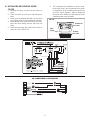
2. Thermostat Connector Cable Installation.
a. A thermostat connector cable is provided to
connect the air conditioner/heat pump control
box to the thermostat. The male end of this
connector goes to the thermostat. The female
end of the cable goes to the air conditioner/
heat pump. See FIG. 15.
F. WIRING REQUIREMENTS
1. Route a copper 1.5 mm2, with ground, 220 - 240
VAC supply line from the time delay fuse or circuit
breaker box to the roof opening.
a. This supply line must be located in the front
portion of the 36.2 cm x 36.2 cm opening.
b. The power MUST be on a separate 10 Amp
time delay fuse or 10 Amp circuit breaker.
c. Make sure that at least 38 cm of supply wire
extends into the roof opening. This ensures
an easy connection at the junction box.
d. Wiring must comply with all national and local
wiring codes.
e. Use a steel sleeve and a grommet or equivalent
methods to protect the wire where it passes
into the opening.
2. Route a dedicated 12 VDC supply line (0.50 mm2
to 0.75 mm2) from the caravan's converter (fi ltered
terminals) or battery to the roof opening.
a. This supply line must be located in the front
portion of the 36.2 cm x 36.2 cm opening.
b. Make sure that at least 38 cm of supply wire
extends into the roof opening.
3. If a furnace is to be controlled by the system, the
two furnace thermostat leads must be routed to
the roof opening. Make sure at least 38 cm of
the furnace thermostat wires extend into the roof
opening.
4. Route thermostat connector cable into the roof
opening. Make sure 38 cm of cable extends into
the roof opening, and 10 cm extends from the wall
at the thermostat mounting location. See Section
G-2.
G. ANALOG THERMOSTAT & CABLE
INSTALLATION
1. Analog Thermostat Location
The proper location of the thermostat is very
important to ensure that it will provide a comfort-
able Caravan temperature. Observe the following
general rules when selecting a location:
a. Locate the analog thermostat 140 cm above
the fl oor.
b. Install the analog thermostat on a partition,
NEVER on an outside wall.
c. NEVER expose it to direct heat from lamps,
sun or other heat producing items.
d. Avoid locations close to doors that lead out-
side, windows or adjoining outside walls.
e. Avoid locations close to supply registers and
the air from them.
f. A 2.5 cm diameter hole will be needed to route
the thermostat connector cable female end
through the wall. See Section F-4.
Female End To
Air conditioner/
heat pump
FIG. 15
Male End To
Thermostat
5 M Thermostat
Connector Cable
b. Choose the shortest, direct route from the
36.2 cm x 36.2 cm opening to the thermostat
location selected.
c. Consider where screws, nails or staples might
contact the cable.
d. Leave approximately 10 cm of cable extending
through the wall for connection to the thermo-
stat.
e. Leave approximately 38 cm of cable extending
into the 36.2 cm x 36.2 cm opening for con-
nection at unit.
3. Analog Thermostat Installation.
a. Connect the thermostat connector cable
protruding from the wall onto the pre-wired
thermostat connector cable.
b. Gently push the two connectors together until
a snap is heard and the lock on the male con-
nector is latched on the female connector.
c. Gently feed the connectors through the hole in
the wall until the thermostat can mount fl ush.
d. Remove the cover from the thermostat by start-
ing at one corner and lifting it off the base.
e. Mount the thermostat level on the wall using
the screws provided in the locations shown in
fi gure. 16.

9
f. Place the cover on the thermostat and push
until and audible click is heard.
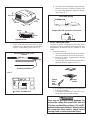
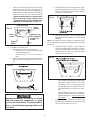
1. Installation Of Ceiling Template
a. Check gasket alignment of the air conditioner/
heat pump over the roof opening and adjust
if necessary. Unit may be moved from below
by slightly lifting and moving. See FIG. 20.
Do not slide the unit. This may damage the
roof gasket attached to the bottom and may
create a leaky installation.
FIG. 19 Divider Plate
Ceiling Template
Front Return Air
Cover Rear
Return Air
Grill
This unit weighs approximately 45 Kg. To
prevent back injury, use a mechanical hoist
to place Air conditioner/heat pump on roof.
FIG. 18
FRONT
I. INSTALLING THE AIR CONDITIONER/HEAT
PUMP
FIG. 20 Center Unit From Below
Roof
Gasket
FIG. 17
H. PLACING AIR CONDITIONER/HEAT PUMP
ON THE ROOF
1. Remove the air conditioner/heat pump from the
carton and recycle. See FIG. 17.
2. Place the air conditioner/heat pump on the roof.
3. Lift and place the unit over the prepared opening
using the gasket on the unit as a guide blunt end
goes to rear. See FIG. 18.
4. Place the return air kit inside the caravan. This box
contains mounting hardware for the air conditioner/
heat pump and will be used inside the caravan. See
FIG. 19.
This completes the outside work. Minor adjust-
ments can be done from the inside of the caravan
if required.
b. Remove return air cover and ceiling template
from the 3105007 or 3105935 carton.
c. Locate the four 20 cm long unit mounting bolts
packed inside the analog control kit box.
d. Pull down the unit's electrical cord into 36.2
cm x 36.2 cm opening. See FIG. 21.
Thermostat
Cable
Gasket
Pull Electrical
Cord Down
FIG. 21
AC Power
Supply
e. Hold the ceiling template up to the 36.2 cm x
36.2 cm opening. Be sure the large plate faces
the rear of the caravan.

10
f. Start each mounting bolt through the ceiling
template and up into the unit base pan by
hand. Install wood screws (not supplied) in
each end of the ceiling template. This insures
a tight fi t of the return air cover to ceiling.
Tighten mounting bolts to compress gas-
ket to 13 mm this will be a torque of 4.5
- 5.0 NM. The bolts are self locking so over
tightening is not necessary. See FIG. 22.
2. Installation of Divider Plate
a. Measure the ceiling to roof thickness:
• If distance is 5 - 9.5 cm, remove perforated
tab from divider plate.
• If distance is 9.6 - 14 cm, remove no
tabs.
b. Remove the backing paper from double sided
tape located on ceiling template. See FIG.
23.
c. Place divider plate up to bottom of air condi-
tioner/heat pump base pan fi rmly. The foam
tape on the divider plate must seal to bottom
of base pan. See FIG. 24.
d. With slight pressure push the divider plate
against the double sided tape on the ceiling
template.
Note: The adhesive on the insulation is extremely sticky.
Be sure the part is located where desired before pressing
into place.
e. Locate the 18 cm x 45.5 cm self -adhesive
insulation supplied with the return air kit. Re-
move the backing paper from the insulation
and carefully stick onto the ceiling template
divider panel. See FIG. 25.
FIG. 23
5 - 9.5 cm
Improper installation and sealing of divider
plate will cause the compressor to quick
cycle on the cold control. This may result in
fuse or circuit breaker opening and/or lack
of cooling.
FIG. 24
FIG. 25
FIG. 22
Finger
Tight
Front Of Vehicle
Tighten to com-
press gasket To
13 mm Or 4.5
-5.0 NM
Roof
Gasket
Wood
Screws
• Excess width is intended to seal the divider
plate to the sides of the 36.2 cm x 36.2
cm opening. This is to help prevent cold
air discharge from circulating into the air
conditioner/heat pump return air open-
ing.
• If the insulation is too high, stick excess
height of insulation to the air conditioner/
heat pump base pan. Do not cover up unit
rating plate.
f. Place the analog control box on the ceiling
template with the white 6 pin connector plug
on the side as shown in FIG. 26.

11
FIG. 26
Blunt Point
Screws
9 Pin Plug
9 Pin To 6 Pin
Adapter
Control
Box
Front Of Caravan
White 6 Pin Connector
On Control Box
Remove
Hang Tag Up
Through
Place Cold
Control In
Center Of
Coil On 2nd
Tube From
FIG. 27 Disconnect 220 - 240 volt AC. Failure to follow
these instructions could create a shock haz-
ard causing death or severe personal injury.
g. Connect the 9 pin plug from the unit to the 9
pin plug on the adapter cable, and the 6 pin to
the control box. The plugs are polarized and
will fi t only one way. See FIG. 26.
J. Wiring The System
Reach up into the return air opening and pull the re-
maining wires down.
1. Connection Of Low Voltage Wires
a. Connect the previously run 12 VDC to the red
and black wires protruding from the units return
air opening. Connect +12 VDC to the red wire;
–12 VDC to the black wire.
b. Connect the previously run furnace thermostat
wires (if applicable) to the blue/white wires
protruding from the units return air opening.
The polarity of these connections does not
matter.
c. Connect the thermostat connector cable into
the mating connector from the control box.
2. Connection of 220 - 240 Volt AC Power Supply
a. Route power supply line through strain relief
into junction box on side. Tighten connector,
being careful not to pinch or short wires.
b. Connect line to black; neutral to white; and
green/yellow to ground wire using appropriate
sized twist connectors.
c. Tape the twist wire connectors to the supply
wire to assure they don't vibrate off.
d. Push the wires into the box.
e. Install the cover onto the junction box.
Disconnect the positive (+) 12 volt DC terminal
at the supply battery. Damage to equipment
could occur if the 12 volt DC is not shut off.
FIG. 27A
Wrap Closed Cell Foam
Insulation Around Cold
Control Switch
Snap The Open Loop
Of Spring Clip On
Second Tube In
Center OF Evapora-
tor Coil
• Keep wires away from heat strip (if appli-
cable) and sharp edges to prevent damag-
ing the wires. Use wire ties if necessary.
• Remove installation notice hang tag from
freeze control.
i. Install two 10 mm blunt point screws provided
through the ceiling template and into the holes
in the control box. See FIG. 26.
This appliance is equipped with a 3-wire
(grounded) system for protection against
shock hazard. Make sure that the appliance
is wired into a properly grounded 220 volt AC
circuit and the polarity is correct. Failure to
do so could result in death, personal injury
or damage to the equipment.
h. Place the cold control (3310137 control not
equipped) switch up through the base pan and
on the second refrigerant tube from the bot-
tom in the center of the evaporator coil. Make
sure the spring clip is fastened securely to the
tubing and the cold control surface is making
contact with aluminum fi ns on evaporator coil.
See FIGS. 27 & 27A.

12
FIG. 28
Return Air
Cover
Hole
Plugs Return
Air Grill
K. INSTALLING DECORATIVE INSIDE
COVER
1. Remove the return air grill from the return air
cover.
2. Place the return air cover up to the ceiling tem-
plate.
3. Install cover to template with #8 x 10 mm blunt
point Phillips head screws provided (6 required).
4. Reinstall fi lter return air grill into return air cover.
Align tabs with mating notches and snap into
place
5. Install two hole plugs into screw holes in back of
return air cover. See FIG. 28.
AIR CONDITIONER 6-9 PIN ADAPTER
6. This completes the installation of the air condi-
tioner/heat pump. We recommend that power
be supplied to the air conditioner/heat pump and
check for proper operation. Refer to Operating
Manual or Users Guide for a description of the air
conditioner/heat pump operation.

13
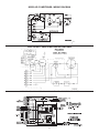
3253.336 AIR CONDITIONER WIRING DIAGRAM
WIRING DIAGRAM FOR 3310086 AIR CONDITIONER HEAT STRIP RELAY KIT
3309270.001
MOTOR
GRN/YEL
5
6
2
3
4
1
7
2
3
GRN/YEL
BLK
YEL
RED
CAP
FAN
BRN
WHT
BRN
WHT
BLU
GRN/YEL
WHT
PTCR
START
CAP CAP
RUN
COMPRESSOR
C
RS
O.L.
WHT WHT
RED RED
ELECTRICAL BOX
HEATING ELEMENT
HEATING ELEMENT
9 PIN
9 PIN
3 PIN
3 PIN
1BLK BLK
LIMIT SWITCH
FAN
B3351 AIR CONDITIONER- WIRING DIAGRAM

14
3254.341 HEAT PUMP WIRING DIAGRAM
WIRING DIAGRAM FOR 3310137 HEAT PUMP RELAY KIT
HEAT PUMP 6-9 PIN ADAPTER
-
 1
1
-
 2
2
-
 3
3
-
 4
4
-
 5
5
-
 6
6
-
 7
7
-
 8
8
-
 9
9
-
 10
10
-
 11
11
-
 12
12
-
 13
13
-
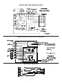 14
14


Dometic Caravan Roof Mount AC_Heat Pump_Model B3200-B3300_Type 3253.336-B3351.531-3254.341 Installation guide
- Category
- Split-system air conditioners
- Type
- Installation guide
Ask a question and I''ll find the answer in the document
Finding information in a document is now easier with AI
Related papers
-
Dometic Caravan Roof Mount AC_Heat Pump_Model B3200-B3300_Type 3253.336-3254.341 Installation guide
-
-
-
-
-
-
-
-
-