Page is loading ...

INSTALLATION &
OPERATION MANUAL
IPSi1200 Series
PURE-SINE INVERTER
8128 River Way, Delta B.C. V4G 1K5 Canada T. 604.946.9981 F. 604.946.9983 TF. 800.668.3884 (US/CANADA)
www.analyticsystems.com
An ISO9001 Registered Company Battery Chargers • Inverters • Power Supplies • Voltage Converters

2
1. SAVE THESE INSTRUCTIONS — This manual contains important safety and operating
instructions for the inverter.
2. Do not expose the inverter to rain or snow.
3. Use of an attachment not recommended or sold by the inverter manufacturer may result
in a risk of re, electric shock, or injury to persons.
4. Do not disassemble the inverter; take it to a qualied serviceman when service or repair
is required. Incorrect reassembly may result in a risk of electric shock or re.
5. To reduce risk of electric shock, disconnect the inverter from the input power before at-
tempting any maintenance or cleaning. Turning off controls will not reduce this risk.
6. Never place the inverter directly above a battery; gases from the battery will corrode and
damage the inverter.
7. Never allow battery acid to drip on the inverter.
HEAVY DEVICE - The IPSi1200 weighs approximately 30lbs. Please use appropriate safety
measures when lifting or moving this device.
Medical Equipment Notice
Analytic Systems does not recommend the use of their products in life support
applications where failure or malfunction of this product can be reasonably
expected to cause failure of the life support device or to signicantly affect its
safety or effectiveness. Analytic Systems does not recommend the use of any
of its products in direct patient care. Examples of devices considered to be life
support devices are neonatal oxygen analyzers, nerve stimulators (whether used
for anesthesia, pain relief, or other purposes), auto-transfusion devices, blood
pumps, debrillators, arrhythmia detectors and alarms, pacemakers, hemodialysis
systems, peritoneal dialysis systems, neonatal ventilator incubators, ventilators
for both adults and infants, anesthesia ventilators, and infusion pumps as well as
any other devices designated as “critical” by the U.S. FDA
GROUNDING AND AC POWER CORD CONNECTION INSTRUCTIONS — Inverters
should be grounded to reduce risk of electric shock. This inverter is equipped with a
chassis grounding stud, and electric receptacles capable of accepting an equipment-
grounding conductor and a grounding plug.
INVERTER
IMPORTANT SAFETY INSTRUCTIONS

32
TABLE OF CONTENTS
• Front Cover
• Product Warnings and Advisories
• Table of Contents
• Introduction
• Box Contents
• Main Parts
• Operation
• Installation
• Product Options
• Troubleshooting
• Specications
• Warranty
Revised - February 5, 2017
Copyright (2005-2017) Analytic Systems Ware (1993) Ltd.

4
The IPSi1200 series of Intelligent Pure Sinewave Inverters are designed specically for running
computers and other sensitive AC loads in rugged, mobile, off-grid environments. This unit
produces up to 1200 watts of pure sine wave AC power, identical to a conventional AC outlet.
The IPSi1200 Inverter is run by a sophisticated Digital Signal Processor (DSP) for optimal control
and the maximum operating efciency. The heavy-duty Toroidal Power Transformer steps up the
low voltage AC produced by the Power MOSFET Transistors to 110 or 220 VAC at 50 Hz or 60 Hz
and lters the AC output to reduce or eliminate electrical noise that can interfere with sensitive
communications equipment.
With the Ofine UPS option, this unit has an additional AC Input connection and can function
as a backup power supply. In the event of an AC power failure, the inverter will automatically
switch to using its DC power source to power the load until such time that power is restored.
Using the free-to-download InverterWizard software, you can customize the Inverter’s
capabilities, selecting output frequency and voltage as well as setting the unit’s low voltage
shutdown parameters from any PC through a standard USB interface.
FEATURES
• ‘Pure Sine Wave’ 110 VAC / 60 Hz or 220 VAC / 50 Hz fully regulated output, exactly the
same as commercial AC.
• Digitally-controlled for precision frequency (± 0.01 Hz) at either 50 or 60 Hz.
• 1200 Watts output power sufcient for a complete computer workstation and more.
• Proven MOSFET technology and sophisticated Digital Signal Processor for efcient and
reliable operation.
• Illuminated ON-OFF switch for positive indication of proper operation.
• Heavy input ltering to shield other devices sharing the same battery.
• Transformer type output to protect computers and other sensitive equipment from surges
and spikes.
• Low voltage warning, short circuit protection, and shutdown circuitry to protect the load.
• Over voltage and over temperature warning and shutdown circuitry to protect the inverter.
• LED indicators and a buzzer to bring attention to the cause of the shutdown.
• One circuit breaker protected AC receptacle plus a hard wire terminals for easy connec-
tion.
Introduction

54
Box Contents
The box you have received should contain the following:
• One IPSi1200 Series Pure-Sine Inverter
• One MicroUSB to USB cable
• This manual
• One Warranty Card
If anything is missing or damaged, please contact your dealer or Analytic Systems for a replacement
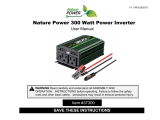
1. Remote Control Connection Port
2. MicroUSB Port
3. DC Input Connection: Marathon Power
Stud Block (1/4” studs)
4. Chassis Grounding Stud
5. Indicator LEDs
6. Lighted ON/OFF button
7. AC Output: Phoenix VDFK
Terminal Block
8. Thermal Carling 15 A
Circuit Breaker
9. AC Output: 5-15 NEMA Outlet
Main Parts
1
3
8
7
9
2
5
4
Front Panel
6

6
Operation
Controls and Indicators
Push the ON/OFF push button to energize the circuitry. The ON/OFF button and Invert LED will
start glowing to indicate the output terminals or receptacle are supplied with AC power. Then
either 50Hz or 60Hz LED glow depending on the unit’s output frequency setting.
The IPSi1200 Inverter has a lighted ON/OFF push button, microUSB port and eight LED
indicators. The ON/OFF button is used to turn the unit on and off. It lights up to indicate the
presence of AC power at the receptacles.
The microUSB port is used to connect the unit to a laptop computer running the InverterWizard
software which can be used to update the unit’s operating parameters and rmware. For more
information, see the InverterWizard section.
The eight LED indicators, labelled 1 through 8, are used to identify the operating condition
of the Inverter. Their functions are detailed below; for more information regarding alarm
conditions, see the Troubleshooting section.
1. Low Voltage: This LED blinks red when the input voltage is near the lower limit for
proper operation. It glows red when the input voltage is too low for proper operation The
Bypass LED will also glow Red and the On/Off button will not be lit up.
2. High Voltage: This LED blinks red when the input voltage is near the upper limit for
proper operation. It glows red when the input voltage is too high for proper operation.
The Bypass LED will also glow Red and the On/Off button will not be lit up. The inverter
can be damaged if the input voltage exceeds the maximum rating, excess voltage dam-
age is not covered under warranty.

76
3. Over Temp: This LED blinks red if the inverter’s internal temperature is approaching the
safe limit. The inverter will derate its maximum power rating to try to maintain a safe
operating temperature. The Bypass LED will also glow Red and the On/Off button will not
be lit up.
4. Over Load: This LED blinks red if the load on the inverter reaches the continuous rating.
It glows red if the load on the inverter reaches the maximum rating.
5. 50 Hz: This LED glows green if the inverter is set for 50 Hz output. This setting can be
changed using InverterWizard.
6. 60 Hz: This LED glows green if the inverter is set for 60 Hz output. This setting can be
changed using InverterWizard.
7. Bypass: This LED glows green if the inverter is in Bypass mode acting as UPS. For more
information on the UPS option, see the Ofine UPS section. This LED glows red if the
inverter experiencing an alarm condition
8. Invert: This LED glows green when the inverter is in normal operation.
InverterWizard Program
This Inverter is delivered preset for the input voltage, output voltage and frequency shown on
the label. If these parameters are satisfactory, the Inverter can be put directly into service.
The normal shutdown parameters are set for the lowest battery voltage the Inverter will
support are: 12 Volts for a -12 model, 24 Volts for a -20 model and 48 Volts for a -40 model.
If the Inverter is powered by alternate voltage such as 32 or 36 volts for a -20 model or 72 volt
rail (64 volt nominal) for a -40 model, then the low voltage shutdown parameters will need to
be adjusted. You can do so using the free-to-download InverterWizard software from
www.analyticsystems.com
Connect the Inverter to the laptop using the microUSB port on the front pane and supplied
cable then open InverterWizard. From InverterWizard, you can:
• Adjust the low voltage shutdown parameters (to match battery voltage)
• Adjust the Output Frequency (50 or 60 Hz)
• Adjust the Output Voltage (+/- 10 percent range at 1 VAC intervals)
• Update the Inverter’s rmware
• Graph Input Voltage, Input Current, Output Voltage and Output Current data.

8
Installation
MOUNTING
Mount the unit in a DRY location. Mount the unit in a ventilated area. Allow at least 1 inch of
clearance around the unit for adequate cooling. The unit must be mounted on a at horizontal
surface. The heavy-duty toroidal power transformer inside the inverter weighs 30+ pounds.
Under severe vibration, it could break free from its single mounting bolt unless the unit is
mounted horizontally.
WARNING: The case must be bonded appropriately to the grounding system
of the vehicle or marine vessel
The case of this Inverter is connected to AC Ground and AC Neutral to meet regulatory
requirements and to reduce the possibility of it generating any radio frequency interference.
On a vehicle, bond the case to the frame and on a marine vessel bond the case to the hull. A
chassis grounding stud is provided on the front panel. To ensure proper grounding, check the
connection with an ohmmeter. The case is isolated from the DC Input, so the DC power can be
on a different ground from the AC output.
WARNING: Do not mount the unit where explosive gases may accumulate
A slight arc may occur when the power leads are connected, and in the unlikely event of a
failure, sparks may be generated inside the unit.
DC INPUT CONNECTION
This unit is equipped with a Marathon Block connector with 4 1⁄4” studs to serve as a DC input
connection. An externally supplied circuit breaker or fuse is required for safe operation.
1. Prepare a circuit breaker protected power source for the IPSi1200 Series Inverter, making
sure the breaker is OFF.
2. Connect the positive terminal of input power to the upper terminal block studs using RED
AWG12 stranded wire.
3. Connect the positive terminal of input power to the lower terminal block studs using
BLACK AWG12 stranded wire.
4. Turn the circuit breaker ON, the ON/OFF button will start glowing indicating AC power at
the output receptacle. The Inverter is ready for operation.
TIP: Make sure the wire insulation butts tightly up to the terminal
For maximum safety, no non-insulated wire should be visible. Trim the length of non-insulated
wire if necessary.
CAUTION: Do not reverse connect the input wires.
This will cause serious Damage to the Inverter and will not be covered by Warranty.

98
AC OUTPUT CONNECTIONS
This unit is equipped with two possible AC Output connections.
• A standard NEMA 5-15 AC receptacle is provided for connection. This connection is
protected by a standard 15A circuit breaker.
• A 30 amp, 250V rated CSA/UL approved Phoenix VDFK terminal block is also provided for
wiring to a distribution panel. It is wired as follows:
This terminal block is NOT protected by a circuit breaker so each device wired to the
distribution panel must have its own breaker. Ensure that the total average load of all the
devices does not exceed the continuous current rating of the unit.
CAUTION: Do not apply AC voltage to either of these connection
This will damage the Inverter and is not be covered under warranty.
DISCONNECTION
If the unit must be disconnected for storage or service:
1. Turn off the unit by pressing the ON/OFF button.
2. Disconnect the DC input power.
3. Press the ON/OFF button and wait 30 seconds to unit to discharge the internal capacitors.
The unit is ready for storage or service.
Block Color Function
Grey AC Neutral
Green / Yellow AC Ground
Black AC Hot

10
Ofine UPS (Optional)
The Ofine UPS (Uninterrupted Power Source) Option allows the Inverter to work as a backup
power source in the event of external AC power failure.
To set up the Ofine UPS
1. Connect the external AC power source to the AC Input Connection.
2. Connect the batteries to the DC Output Connection.
3. Connect the load to the AC Output Connection. The Bypass LED will glow green
indicating the load is connected to external AC power.
In the event that external power fails, the Inverter will sense the malfunction, power up, and
take over supplying AC power to the load. It will continue to work until either time the external
AC power is restored or the batteries become discharged.
The external AC voltage thresholds for the Inverter to take over supplying AC Power or to
stop supplying AC power are all factory-preset to typical values. However, you can use the
InverterWizard software to adjust these values to t your specic needs.
Choose batteries with enough capacity to ensure that the Inverter can power the load for
the required amount of time in the event of AC power failure. For example, a 2000W Inverter
running from 24 VDC input will draw ~100 amps, so for 2 hours of runtime the minimum
required battery capacity is 280 amps hours of capacity at 24 volts.
Special Services & Options
A Line AC Detect & Autoswitch UPS
C
COTS
|
MIL461F, MIL810G (MIL Connectors) (Vibration Protection) (Wide temP {-40 to +55
o
c})
(in-house tested and rePort for each unit- aVailable as add on to m oPtion)
E European ROHS compliant (lead free manufactured)
I MIL461F (in-house tested and rePort for each unit- aVailable as add-on to m oPtion)
J MIL810G (in-house tested and rePort for each unit- aVailable as add-on to m oPtion)
M Military Rugged Package (MIL Connectors) (Vibration Protection) (Wide temP {-40 to +55
o
c})
U Safety Special Inspection (csa/ul) (bca/PWs 610/1000 = certified csa c22.2/no.107.1/ul 1012)
X Heavy Duty Ruggedization (Vibration Protection) (Wide temP {-40 to +55
o
c})
Z No Conformal Coating

1110
Remote Port (Optional)
This port is intended to be used with an Analytic Systems Digital Remote Control, but it can
also be used for as a Remote On/Off switch, Isolated RS232 Communications terminal and
Dry Contact Output Fail indicator. The remote port uses a standard RJ45 style connector with
proprietary connections. Do not connect this port to a computer. The wire colors described
below correspond to colors found in any standard T-568B network cable.
CAUTION: Do not connect this port to a computer
This will cause serious damage to the Inverter and the computer. This will not be covered
under warranty.
Pin Number Wire Color Function
1 White/Orange Stripe Remote ON/OFF
2 Orange Digital Ground
3 White/Green Stripe +12V Out
4 Blue RX RS232
5 White/Blue Stripe TX RS232
6 Green Gnd RS232
7 White/Brown Dry Contact Relay
8 Brown Dry Contact Relay
Remote On/Off
Pins 1 (White/Orange) and 2 (Orange) are used to turn the Inverter ON or OFF. Connect them
together through a switch or relay to turn the Inverter OFF and disconnect them to turn the
Inverter ON. The main power switch must be ON for this connection to function.
Isolated RS232 Communications
Pins 4 (Blue), 5 (White/Blue) and 6 (Green) are an isolated RS232 port that can be used for
communication to/from the Inverter. Information on the standard data structure or custom
programming is available from the factory. Pin 4 is RX, Pin 5 is TX and Pin 6 is Return.
Dry Contact Output Fail Relay
Pins 7 and 8 (White/Brown and Brown) connect to the contacts of an Output Fail relay
controlled by the processor. The contacts will be CLOSED if the Inverter is operating normally
and OPEN if the Inverter has failed.

12
Troubleshooting
This unit is equipped with eight LED indicators and an alarm buzzer to help diagnose any alarm
conditions. In the event of malfunction, the unit will sound the buzzer prior to shutting down.
You should immediately check the LED indicators to determine the cause of the shutdown.
LED Indicator
Meaning
LOW VOLTAGE
The input voltage is too low for normal operation.
Fix:
Check the rating of the input voltage. Check that the cables and
connections are not corroded or damage.
If using InverterWizard, make sure the Low Input threshold is set
properly for the battery voltage you are using, for example:
• ~21V for a 24V battery
• ~28V for a 32V battery
• ~31V for a 36V battery
HIGH VOLTAGE
The input voltage is too high for normal operation.
Fix:
Check the rating of the input voltage.
The Inverter can be damaged if the input voltage exceeds the
maximum rating. Over-voltage damage is not covered under warranty.
OVER TEMP
The internal temperature is too hot for normal operation.
Fix:
Check that the cooling fans are functioning. If the fans are still
running, remount the Inverter for improved ventilation.
If the fans are NOT running, the Inverter must be returned to the
manufacturer for repair.
OVER LOAD
The load is drawing too much current from the Inverter.
Fix:
Reduce the load by disconnecting some devices connected to the
Inverter’s AC output.

1312
Specications
Input
Nominal Voltage 12 VDC 24, 28, 32 or 36 VDC 48 or 72 (Rail) VDC
Actual Voltage 11 - 15 VDC 20 - 45 VDC 40 - 80 VDC
Input Amps (max) 120A 60A 30A
Input Fuse None, external fuse or breaker required
Output
Actual Voltage 110 +/- 2 VAC 220 +/- 4 VAC
Output Amps 10A (cont) / 12A (peak) 5A (cont) / 6A (peak)
Circuit Breaker NEMA 5-15 outlet protected by 15A Breaker; Phoenix Block unprotected
Output Frequency 50.00 or 60.00 Hz ± 0.01 Hz (user selectable)
Output Distortion <2% at 1200 Watts into resistive load
Regulation (Line & Load) < +/- 2.0%
Duty Cycle Continuous 100% for 24 hours per day
* Specications subjects to change without notice.
General
Efciency > 90% @ Maximum Output
Temp. Range -25°C to +40°C @ Maximum Output
Isolation Input-Output, Input-Case & Output-Case: 1500 VDC
Length 13.0 in / 33.0 cm
Width 9.0 in / 22.9 cm
Height 7.8 in / 19.8 cm
Clearance 1 Inch (2.5 cm) all around
Material Marine Grade Aluminum
Finish Black Powder Epoxy/Black Anodized
Fastenings 18-8 Stainless
Weight 30 lb / 13.6 kg
Connections
DC In – Marathon ST722B2502UH, 175 Amp, 300V Rating c/w Protective Snap
On Cover
AC Out (1) – 1 x NEMA 5-15 receptacle or 1 x 16A 250V CEE 7/7 receptacles
AC Out (2) – 1x Phoenix VDFK Terminal Block (Gray, Green-Yellow, Black)
AC In – 1x 30A hard wire connection (with Off-Line UPS Option)
Designed and manufactured by: ANALYTIC SYSTEMS WARE (1993) LTD.
8128 River Way
Delta, BC V4G 1K5 Canada
p. 604.946.9981 f. 604.946.9983
tf. 800.668.3884 US/Canada
www.analyticsystems.com [email protected]

14
Page intentionally left blank

15
Limited Warranty
1. The equipment manufactured by Analytic Systems Ware (1993) Ltd. (the “Warrantor”) is warranted to be free
from defects in workmanship and materials under normal use and service.
2. This warranty is in effect for 3 years from the date of purchase by the end user.
3. Analytic Systems will determine eligibility for warranty from the date of purchase shown on the warranty card
when returned within 30 days, or
a. The date of shipment by Analytic Systems, or
b. The date of manufacture coded in the serial number, or
c. From a copy of the original purchase receipt showing the date of purchase by the user.
4. In case any part of the equipment proves to be defective, the Purchaser should do the following:
a. Prepare a written statement of the nature of the defect to the best of the Purchasers knowledge, and
include the date of purchase, the place of purchase, and the Purchasers name, address and telephone
number.
b. Call Analytic Systems at 800-668-3884 or 604-946-9981 and request a return material authorization
number (RMA).
c. Return the defective part or unit along with the statement at the Purchasers expense to the Warrantor;
Analytic Systems Ware (1993) Ltd., 8128 River Way, Delta, B.C., V4G 1K5, Canada.
5. If upon the Warrantor’s examination the defect proves to be the result of defective material or workmanship,
the equipment will be repaired or replaced at the Warrantor’s option without charge, and returned to the
Purchaser at the Warrantor’s expense by the most economical means. Requests for a different method of return
or special handling will incur additional charges and are the responsibility of the Purchaser.
6. Analytic Systems reserves the right to void the warranty if:
a. Labels, identication marks or serial numbers are removed or altered in any way.
b. Our invoice is unpaid.
c. The defect is the result of misuse, neglect, improper installation, environmental conditions, non-authorized
repair, alteration or accident.
7. No refund of the purchase price will be granted to the Purchaser, unless the Warrantor is unable to remedy the
defect after having a reasonable number of opportunities to do so.
8. Only the Warrantor shall perform warranty service. Any attempt to remedy the defect by anyone else shall
render this warranty void.
9. There shall be no warranty for defects or damages caused by faulty installation or hook-up, abuse or misuse of
the equipment including exposure to excessive heat, salt or fresh water spray, or water immersion except for
equipment specically stated to be waterproof.
10. No other express warranty is hereby given and there are no warranties that extend beyond those described
herein. This warranty is expressly in lieu of any other expressed or implied warranties, including any implied
warranty of merchantability, tness for the ordinary purposes for which such goods are used, or tness for a
particular purpose, or any other obligations on the part of the Warrantor or its employees and representatives.
11. There shall be no responsibility or liability whatsoever on the part of the Warrantor or its employees and rep-
resentatives for injury to any person or persons, or damage to property, or loss of income or prot, or any other
consequential or resulting damage which may be claimed to have been incurred through the use or sale of the
equipment, including any possible failure of malfunction of the equipment, or part thereof.
12. The Warrantor assumes no liability for incidental or consequential damages of any kind.

Register Products Online | www.analyticsystems.com/support/warranty-registration
DESIGNED AND MANUFACTURED BY
800-668-3884
604-946-9983
www.AnalyticSystems.com
8128 River Way
Delta, BC V4G 1K5 | Canada
Battery Chargers • Inverters • Power Supplies • Voltage Converters
/