
Installation &
Operation Manual
BCA-PWS-480-36
Transit Power Supply/
Charger
8128 River Way, Delta B.C. V4G 1K5 Canada T. 604.946.9981 F. 604.946.9983 TF. 1.800.668.3884 (US/CANADA)
www.analyticsystems.com

2
Copyright (2005-2013) Analytic Systems Ware (1993) Ltd.

3
IMPORTANT & SAFETY INSTRUCTIONS
SAVE THESE INSTRUCTIONS — is manual contains important safety and operating instructions for the
converter.
1) CAUTION — To reduce risk of injury, charge only NiCd type rechargeable batteries. Other types of bat-
teries may burst causing personal injury and damage.
2) Use of an attachment not recommended or sold by the power supply/charger manufacturer may result in a
risk of re, electric shock, or injury to persons.
4) Do not disassemble converter; take it to a qualied serviceman when service or repair is required. Incor-
rect reassembly may result in a risk of electric shock or re.
5) To reduce risk of electric shock, disconnect power supply/charger from batteries or other DC supply
before attempting any maintenance or cleaning. Turning o controls will not reduce this risk.
Analytic Systems does not recommend the use of the BCA-PWS-480-36 power supply/charger in life support
applications where failure or malfunction of this product can be reasonably expected to cause failure of the
life support device or to signicantly aect its safety or eectiveness. Analytic Systems does not recommend
the use of any of its products in direct patient care.
Examples of devices considered to be life support devices are neonatal oxygen analyzers, nerve stimulators
(whether used for anaesthesia, pain relief, or other purposes), auto transfusion devices, blood pumps, de-
brillators, arrhythmia detectors and alarms, pacemakers, haemodialysis systems, peritoneal dialysis systems,
neonatal ventilator incubators, ventilators for both adults and infants, anaesthesia ventilators, and infusion
pumps as well as any other devices designated as “critical” by the U.S. FDA.
Introduction
power supply (BC/LVPS)’ system for commuter rail applications. Two identical converters are used for the
Battery charger and Low voltage power supply of the system. e converters rectify 480V AC 3 phase input
and convert it to a regulated lower voltage isolated output. Reliability features include two 10A input breaker,
input under/over voltage shut down, output short circuit shutdown…
Features
In a DC UPS ( Un-interruptible Power Supply ) , the charger simultaneously powers the DC load as well
as the battery. As long as the AC power to the charger is available and the charger is working normally,
the charger will supply the DC load as well as charge / oat the battery. In case the AC power fails or if the
charger stops working, the battery will automatically power the DC load. As soon as the AC power to the
charger is restored, the DC load will once again be fed by the charger and at the same time the battery will be
recharged. CAUTION! Please ensure that the sum of the current drawn by the DC load and the current de-
sired for charging the battery is less than the maximum current capacity of the charger. To use as a DC UPS,
rst switch o the DC load and connect it to the battery. Now connect the battery. Switch on the charger and
then switch on the DC load.

4
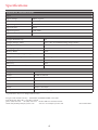
Specications
ELECTRICAL SPECIFICATIONS:
Input
Input Voltage 480Vac 3 phase
Actual (Vac) 432V-528V
Input Amps (max) 4Ax2
Input Breaker 10Ax2
Input Frequency 47Hz-63Hz
Input Power Factor >0.90
Output
Output Nominal (op) 32V
Output Voltage (Max) 41.5V (47V in commissioning charge mode)
Absorption Voltage (VDC) 38.125V
Charging Amps 60A
Battery Banks NiCd
Commissioning Charge Voltage (VDC) 47.5V
Temperature Compensation Coecient -3mV/
0
C per cell
Duty Cycle 100%
Eciency >92%
Regulation (Line & Load) <10mV; <100mV
MECHANICAL SPECIFICATIONS:
Length 34.187 in/868mm
Width 18.030 in/458mm
Height 23.500 in/597mm
Clearance 21.000 in/534mm
Material Stainless Steel
Finish Powder coat white
Weight 270 lbs/122.470kg (apprx.)
Designed and manufactured by: ANALYTIC SYSTEMS WARE (1993) LTD.
8128 River Way, Delta, B.C., V4G 1K5, Canada
phone (604) 946-9981 fax (604) 946-9983 toll free 800-668-3884 US/Canada
email: analyticinfo@analyticsystems.com web site: www.analyticsystems.com Revised Fed 2011
* Specications subjects to change without notice.

5
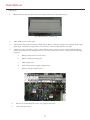
Fig.1: Mounting holes on unit’s top
Installation
◆ Hardware
1. Mount railway charger unit onto train using all four holes provided (Fig. 1).
1. Turn OFF power on the train.
2. Open unit’s door and feed wiring (480V input, Battery Charger output, Low Voltage Power Sup-
ply output, and battery temperature sensor wires) into unit through the rear hole.
3. Connect wiring according to Fig. 2 (from le to right). Wiring is to be routed underneath the
connector panel. Ensure wiring does not touch the converters. Connect wiring in the following
sequence :
a. Battery temperature sensor wires
b. RS232 communication port
c. 480V input wires
d. Low voltage power supply output wires
e. Battery charger output wires
5. Ensure all terminal block screws are properly fastened.
6. Close and lock door

6
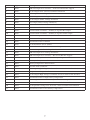
Fault and Error Condition Codes
Fault codes are conditions that cause a shutdown of the BC/LVPS. Error codes are conditions that are consid-
ered out of the normal operating range, but not signicant enough to cause a shutdown.
If a fault or error code is present it will cause the Digital Voltage / Amp-meter Display (DVAM) to alternate
between BC/LVPS voltage/current values and the last 5 error and fault codes.
Fault (F) and Error (E) condition codes (2 digits) are displayed via 2x3 digits, 7seg LCD and 13LED as an
alternate to the normal voltage and current values. However, not all of these directly correspond to a status
LED.
Fault codes are displayed using the format: FXX where XX represents the numerical fault codes range from
01 – 49.Error codes are displayed using the format: EXX where XX represents the numerical error codes
range from 50 – 99.
Troubleshooting
◆ PC Soware
Run the install program. It will install the Metra_LVPS_BC soware in the directory C:\Programming Files\
Metra. It will create a start icon on the desktop. It will install a new item ASW_Metra in the “All Program”
menu that has two entries. One entry is to start the application and the second is an uninstall option to
remove the application from the computer.
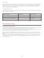
◆ Congurable Parameters
e following list of conguration parameters can be changed by the customer via the RS232 serial interface
and the GUI soware package.
Name/Description: Default Value: Allowable Range:
DVAM Display Alternate Rate 5 seconds 1 to 60 seconds
DVAM O during battery operation 100% ON 0 to 100% duty cycle
LVPS output over-current # of retries 3 0 to innity
LVPS output over-current retry interval 5 seconds 1 to 65535 seconds

7
Code: Type: Description:
1 Fault 480 VAC Input Over-Current – LVPS Circuit Breaker tripped
2 Fault LVPS Output Over-Current condition Shutdown
3 Fault BC Output Over-Voltage Shutdown
4 Fault LVPS Output Over-Voltage Shutdown
5 Fault LVPS Output Under-Voltage Shutdown
6 Fault BC Output Under-Voltage Shutdown
7 Fault BC Internal Fault condition – a shutdown results
8 Fault LVPS Internal Fault condition – a shutdown results
9 Fault Internal Fault condition – inability to regulate BC output
10 Fault Internal Fault condition – inability to regulate LVPS output
11 Fault BC Over Temperature Condition
12 Fault LVPS Over Temperature Condition
13 Fault BC Shutdown due to Failure
14 Fault LVPS Shutdown due to Failure
15 Fault MOV Alarm Fault Condition (not used at present)
16 Fault 480 VAC Input Under-Voltage Shutdown
17 Fault 480 VAC Input Over-Voltage Shutdown
18 Fault 480 VAC Input Over-Current – BC Circuit Breaker tripped
50 Error Remove Battery from Load (low battery voltage <= 22.5V)
51 Error Battery Polarity Reversal
52 Error Battery Temperature Probe Failure
53 Error Ground Fault Condition
54 Error BC Output High Voltage Condition (between 42VDC and 45VDC)
55 Error Output Low Voltage Condition
56 Error LVPS Output High Voltage Condition (between 42VDC and 45VDC)
57 Error BC Shutdown due to high battery temperature
58 Error LVPS High Current – No Battery Switch-Over attempted
59 Error LVPS Overload Retries consumed – Total Shutdown of LVPS
60 Error LVPS possible wiring error. Detected +Volts on LVPS load terminals
61 Error BC Shutdown due to low battery temperature

8
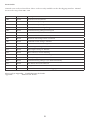
Event Codes
Normal event codes are listed here. ese codes are only available via the data logging interface. Normal
Event codes range from 100 – 199.
Code: Type: Description:
100 Event Transfer load to batteries
101 Event FLOAT Battery Charge Start
102 Event BOOST Battery Charge Start
103 Event Battery Commissioning Charge Start
104 Event Commissioning Charge Interrupted
105 Event 480VAC Restored
106 Event Remove LVPS load from Battery
107 Event BC Heat Sink Temperature is Normal
108 Event LVPS Heat Sink Temp is Normal
109 Event 480VAC is in Normal Range
110 Event LVPS output Voltage is Normal
111 Event BC Output Voltage is Normal
112 Event BC is NOT in current limiting
113 Event LVPS is NOT in current limiting
114 Event Battery Temperature is Normal
115 Event Commissioning Charge Cycle Ended Normally
116 Event AC Power has been removed
117 Event Output Current limit condition (BC or LVPS)
118 Event Start of Firmware; Start of Data logging
Please refer to Appendix… Troubleshooting for details.
Appendix … Firmware for details

9
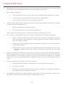
Limited Warranty
1. e equipment manufactured by Analytic Systems Ware (1993) Ltd. (the “Warrantor”) is warranted to be
free from defects in workmanship and materials under normal use and service.
2. is warranty is in eect for:
a. 3 Years from date of purchase by the end user for standard products oered in our catalog.
b. 2 Years from date of manufacture for non-standard or OEM products
c. 1 Year from date of manufacture for encapsulated products.
3. Analytic Systems will determine eligibility for warranty from the date of purchase shown on the warranty
card when returned within 30 days, or
a. e date of shipment by Analytic Systems, or
b. e date of manufacture coded in the serial number, or
From a copy of the original purchase receipt showing the date of purchase by the user.
4. In case any part of the equipment proves to be defective, the Purchaser should do the following:
a. Prepare a written statement of the nature of the defect to the best of the Purchasers knowl-
edge, and include the date of purchase, the place of purchase, and the Purchasers name, ad-
dress and telephone number.
b. Call Analytic Systems at 800-668-3884 or 604-946-9981 and request a return material autho-
rization number (RMA).
c. Return the defective part or unit along with the statement at the Purchasers expense to the
Warrantor; Analytic Systems Ware (1993) Ltd., 8128 River Way, Delta, B.C., V4G 1K5,
Canada.
5. If upon the Warrantor’s examination the defect proves to be the result of defective material or workman-
ship, the equipment will be repaired or replaced at the Warrantor’s option without charge, and returned
to the Purchaser at the Warrantor’s expense by the most economical means. Requests for a dierent
method of return or special handling will incur additional charges and are the responsibility of the Pur-
chaser.
6. Analytic Systems reserves the right to void the warranty if:
a. Labels, identication marks or serial numbers are removed or altered in any way.
b. Our invoice is unpaid.
c. e defect is the result of misuse, neglect, improper installation, environmental conditions,
non-authorized repair, alteration or accident.
7. No refund of the purchase price will be granted to the Purchaser, unless the Warrantor is unable to rem-
edy the defect aer having a reasonable number of opportunities to do so.

8. Only the Warrantor shall perform warranty service. Any attempt to remedy the defect by anyone else
shall render this warranty void.
9. ere shall be no warranty for defects or damages caused by faulty installation or hook-up, abuse or mis-
use of the equipment including exposure to excessive heat, salt or fresh water spray, or water immersion
except for equipment specically stated to be waterproof.
10. No other express warranty is hereby given and there are no warranties that extend beyond those de-
scribed herein. is warranty is expressly in lieu of any other expressed or implied warranties, including
any implied warranty of merchantability, tness for the ordinary purposes for which such goods are used,
or tness for a particular purpose, or any other obligations on the part of the Warrantor or its employees
and representatives.
11. ere shall be no responsibility or liability whatsoever on the part of the Warrantor or its employees and
representatives for injury to any person or persons, or damage to property, or loss of income or prot,
or any other consequential or resulting damage which may be claimed to have been incurred through
the use or sale of the equipment, including any possible failure of malfunction of the equipment, or part
thereof.
12. e Warrantor assumes no liability for incidental or consequential damages of any kind.
8128 River Way, Delta B.C. V4G 1K5 Canada T. 604.946.9981 F. 604.946.9983 TF. 1.800.668.3884 (US/CANADA)
www.analyticsystems.com
-
 1
1
-
 2
2
-
 3
3
-
 4
4
-
 5
5
-
 6
6
-
 7
7
-
 8
8
-
 9
9
-
 10
10


Analytic Systems BCA-PWS-480-36 Owner's manual
- Type
- Owner's manual
- This manual is also suitable for
Ask a question and I''ll find the answer in the document
Finding information in a document is now easier with AI
Related papers
-
 Analytic Systems PWS1510MS Installation & Operation Manual
-
 Analytic Systems BCD605 Installation & Operation Manual
-
 Analytic Systems PWS310 MS Installation & Operation Manual
-
 Analytic Systems FCA500 Operating instructions
-
 Analytic Systems BCA310-220-32 Owner's manual
-
Analytic Systems BCD1000-110-48 Owner's manual
-
 Analytic Systems BCA1000-110-72 Owner's manual
-
 Analytic Systems BCD615-24-12 Owner's manual
-
 Analytic Systems BCA1505M-48 Owner's manual
-
Analytic Systems BCD310-250-24 Owner's manual


