
R6GN - 150 / 180 Series High Efficiency
R6GN-150 Series Shown
Single Package Gas Heating / Electric Cooling Rooftop Units
DO NOT DESTROY THIS MANUAL. KEEP IN A SAFE PLACE FOR FUTURE REFERENCE.
FIRE OR EXPLOSION HAZARD
•Failure to follow safety warnings exactly
could result in serious injury or property
damage.
•Installationandservicemustbeperformed
byaqualiedinstaller,serviceagencyorthe
gassupplier.
•Do not store or use gasoline or other
ammablevaporsandliquidsinthevicinity
of this or any other appliance.
WHAT TO DO IF YOU SMELL GAS
•Donottrytolightanyappliance.
•Donottouchanyelectricalswitch;donot
useanyphoneinyourbuilding.
•Leavethebuildingimmediately.
•Immediatelycall your gassupplierfroma
neighbor’sphone.Followthegassupplier’s
instructions.
•Ifyoucannotreachyourgassupplier,call
theredepartment.
WARNING:
RISQUED’INCENDIEOUD’EXPLOSION
•Le non-respect des avertissements de
sécurité pourrait entraîner des blessures
graves,lamortoudesdommagesmatériels.
•L’installation et l’entretien doivent être
effectués par un installateur qualié, un
organismedeserviceoulefournisseur de
gazstaller,serviceagencyorthegassupplier.
•Nepasentreposerniutiliserdel’essenceni
d’autres vapeurs ou liquides inammables
danslevoisinagedecetappareil,nidetout
autreappareil.
QUEFAIRES’ILYAUNEODEURDEGAZ
•Nepastenterd’allumeraucunappareil.
•Netoucheràaucuninterrupteurélectrique;
n’utiliseraucuntéléphonedanslebâtiment.
•Évacuerl’immeubleimmédiatement.
•Appeler immédiatement le fournisseur de
gazenemployantletéléphoned’unvoisin.
Respecter à la lettre les instructions du
fournisseurdegaz.
•Sipersonnenerépond,appelerleservicedes
incendies.
AVERTISSEMENT
INSTALLATION INSTRUCTIONS

2
IMPORTANT SAFETY INFORMATION .......................3
REQUIREMENTS & CODES .......................................4
GENERAL INFORMATION ..........................................5
About the Rooftop Unit ..............................................5
Before You Install This Equipment .............................5
Locating the Unit .......................................................5
Heating Load .............................................................5
COMBUSTION AIR & VENTING REQUIREMENTS ....6
General Information ...................................................7
Vent Termination ........................................................7
CIRCULATING AIR SUPPLY .......................................8
Air Ducts ....................................................................8
Air Filter Requirements..............................................8
Unconditioned Spaces ..............................................9
Acoustical Ductwork ..................................................9
UNIT INSTALLATION ..................................................9
Packaging Removal ...................................................9
Rigging & Hoisting .....................................................9
Minimum Clearance Requirements .........................10
Rooftop Mounting ....................................................10
Ground Level ...........................................................10
Downflow to Horizontal Conversion ......................... 11
Condensate Drain ...................................................11
GAS SUPPLY & PIPING ............................................11
Leak Check .............................................................12
High Altitude Deration .............................................12
Conversion to LP/Propane ......................................13
ELECTRICAL WIRING ............................................... 14
Pre-Electrical Checklist ...........................................14
Line Voltage ............................................................. 14
Grounding................................................................14
Unbalanced 3-Phase Supply Voltage ......................15
Thermostat / Low Voltage Connections ................... 15
Blower Speed ..........................................................15
Heat Anticipator ....................................................... 16
STARTUP & ADJUSTMENTS ...................................16
Pre-Start Check List ................................................16
Startup Procedures .................................................16
Air Circulation ..........................................................17
System Cooling .......................................................17
System Heating .......................................................17
Verifying & Adjusting Temperature Rise ..................17
Verifying Burner Operation ......................................17
Verifying Operation of Over-Temperature
Limit Control ............................................................17
Verifying & Adjusting Firing Rate .............................18
Manifold Pressure Adjustment ................................18
Refrigerant Charging ...............................................18
OPERATING SEQUENCE .........................................19
Cooling Mode ..........................................................19
Blower Mode ...........................................................19
Heating Mode ..........................................................19
UNIT MAINTENANCE ................................................19
Routine Maintenance ..............................................20
Motor / Bearing Lubrication Requirements ..............20
Cleaning of Burners ................................................20
Cleaning the Heat Exchanger .................................21
Removal of Unit Top Pan .........................................21
REPLACEMENT PARTS ............................................21
COMPONENT FUNCTIONS ......................................22
TROUBLESHOOTING ...............................................22
FIGURES & TABLES .................................................23
Figure 11 - Location of Unit Components ............23
Physical Dimensions ...............................................24
Figure 12 - R6GN 150/180 Series .......................24
Table 3 - Unit Shipping Weights ...........................25
Blower Performance Data .......................................26
Table 4 - R6GN 150 Series ..................................26
Table 5 - R6GN 180 Series ..................................27
R6 Charging Charts ................................................28
Figure 13 - R6GN-150 Series ..............................28
Figure 14 - R6GN-180 Series ..............................29
Electrical Information ............................................... 30
Figure 15 - Ladder Diagram .................................30
Figure 16 - Wiring Diagram ..................................31
Table 6 - Electrical Data .......................................32
Gas Information ....................................................... 33
Table 7- Gas Flow Rates ......................................33
Table 8 - Gas Pipe Capacities .............................. 33
Table 9 - Orifice or Drill Sizes for Nat. Gas ...........34
Table 10 - Orifice or Drill Sizes for LP Gas ........... 34
Table 11- Heating Rise / Range ...........................34
Figure 17 - Gas Valve Label .................................35
INSTALLATION / PERFORMANCE CHECKLIST .....36
TABLE OF CONTENTS

3
IMPORTANT SAFETY INFORMATION
Please read all instructions before servicing this equipment.
Pay attention to all safety warnings and any other special
notes highlighted in the manual. Safety markings are used
frequently throughout this manual to designate a degree
or level of seriousness and should not be ignored.
WARNING indicates a potentially hazardous situation
that if not avoided, could result in personal injury or death.
CAUTION indicates a potentially hazardous situation that
if not avoided, may result in minor or moderate injury or
property damage.
ATTENTION INSTALLERS: It is your responsibility
to know this product better than your customer. This
includes being able to install the product according to
strict safety guidelines and instructing the customer on
how to operate and maintain the equipment for the life of
the product. Safety should always be the deciding factor
when installing this product and using common sense
plays an important role as well. Pay attention to all safety
warnings and any other special notes highlighted in the
manual. Improper installation of the unit or failure to follow
safety warnings could result in serious injury, death, or
property damage. These instructions are primarily intended
to assist qualified individuals experienced in the proper
installation of this appliance. Some local codes require
licensed installation/service personnel for this type of
equipment. After completing the installation, return these
instructions to the customer’s package for future reference.
WARNING:
Improper installation, service, adjustment,
or maintenance may cause explosion, re,
electricalshockorotherhazardousconditions
whichmayresultinpersonalinjuryorproperty
damage. Unless otherwise noted in these
instructions, only factory authorized kits or
accessoriesmaybeusedwiththisproduct.
WARNING:
Donotplacecombustiblematerialonoragainst
the unit cabinet. Do not place combustible
materials, including gasoline and any other
ammablevaporsandliquids, inthevicinity
oftheunit.
WARNING:
PROPOSITION 65 WARNING: This product
contains berglass wool, a product known
to the state of California to cause cancer.
Disturbingtheinsulationofthisproductduring
installation,maintenance,orrepairwillexpose
youtoberglasswool.
• Breathingthismaterialmaycauserespiratory
irritationsormaycauselungcancer.
•Fiberglass wool may also cause eye
irritation,skinsensitization,orotherallergic
responsesinsusceptibleindividuals.
• Always wear goggles, disposable gloves,
longsleevedshirt,andappropriatebreathing
protectionwhenworkingnearthisinsulation.
Ifcontactwithskinoccurs,washimmediately
withsoapandwater.Incaseofcontactwith
eyes, ush immediately with water for at
least15minutes.Contactaphysicianifneeded.
WARNING:
The information listed below and must be
followed during the installation, service,
and operation of this unit. Unqualified
individualsshouldnotattempttointerpretthese
instructionsorinstallthisequipment.Failure
tofollowsafetyrecommendationscouldresult
inpossibledamagetotheequipment,serious
per
sonalinjuryordeath
.
• Thisequipmentcontainsliquidandgaseousrefrigerant
under high pressure. Installation or servicing should only
be performed by qualified trained personnel thoroughly
familiar with this type equipment.
• Before beginning the installation, verify that the unit
model is correct for the job. The unit model number
is printed on the data label. Follow all precautions in
the literature, on tags, and on labels provided with
the equipment. Read and thoroughly understand
the instructions provided with the equipment prior to
performing the installation and operational checkout
of the equipment.
• Never test for gas leaks with an open ame. Use a
commercially available soap solution to check all
connections See pages 12 - 13.
• Follow all precautions in the literature, on tags, and
on labels provided with the equipment. Read and
thoroughly understand the instructions provided with
the equipment prior to performing the installation and
operational checkout of the equipment.
• Thisunitisdesignedonlyforoutdoorinstallationsand
should be located with consideration of minimizing the

4
Combustion&VentilationAir
• US: National Fuel Gas Code (NFGC), Air for
Combustion and Ventilation
• CANADA: Natural Gas and Propane Installation
Codes(NSCNGPIC),VentingSystemsandAirSupply
for Appliances
DuctSystems
• US and CANADA: Air Conditioning Contractors
Association (ACCA) Manual Q, Sheet Metal and
Air Conditioning Contractors National Association
(SMACNA), or American Society of Heating,
Refrigeration, and Air Conditioning Engineers
(ASHRAE)FundamentalsHandbook
Electrical Connections
• US:NationalElectricalCode(NEC)ANSI/NFPA70
• CANADA:CanadianElectricalCodeCSAC22.1
GasPiping&GasPipePressureTesting
• US:NFGCandNationalPlumbingCodes
• CANADA:NSCNGPIC
General Installation
• US:CurrenteditionoftheNFGCandtheNFPA90B.
For copies, contact the National Fire Protection
Association Inc., Batterymarch Park, Quincy, MA
02269; or American Gas Association, 400 N. Capitol,
N.W., Washington DC 20001 or www.NFPA.org.
• CANADA:NSCNGPIC.Foracopy,contactStandard
Sales, CSA International, 178 Rexdale Boulevard,
Etobicoke(Toronto),Ontario,M9W1R3Canada
Safety
• US:(NFGC)NFPA54–1999/ANSIZ223.1andthe
Installation Standards, Warm Air Heating and Air
Conditioning Systems ANSI/NFPA 90B.
• CANADA:CAN/CGA-B149.1–and.2–M00National
StandardofCanada.(NSCNGPIC)
REQUIREMENTS & CODES
• Thisequipmentmustbeinstalledinaccordancewith
instructionsoutlinedinthismanual,allapplicable
local buildingcodes, and the current revisionof
theNationalFuelGasCode(NFPA54/ANSIZ223.1)
ortheNaturalGasandPropaneInstallationCode,
CAN/CGA B149.1.
• Allelectricalwiringmustbecompletedinaccordance
with local, state and national codes and regulations and
withtheNationalElectricCode(ANSI/NFPA70)orin
Canada the Canadian Electric Code Part 1 CSA C.22.1.
• The installer must comply with all local codes and
regulations which govern the installation of this type
of equipment. Local codes and regulations take
precedence over any recommendations contained in
these instructions. Consult local building codes and the
NationalElectricalCode(ANSICI)forspecialinstallation
requirements.
• Air Ducts must be installed in accordance with the
standards of the National Fire Protection Association
“Standards for Installation of Air Conditioning and
Ventilation Systems” (NFPA 90A), “Standard for
Installation of Residence Type Warm Air Heating and Air
ConditioningSystems”(NFPA90B),theseinstructions,
and all applicable local codes.
• ConsultTable11(page34),andtheratingplateforthe
proper circulating air flow and temperature rise. It is
important that the duct system be designed to provide
the correct flow rates and external pressure rise. An
improperly designed duct system can result in nuisance
shutdowns, and comfort or noise issues.
• Thisunitisdesignedforoutdoorinstallationsonlyand
should be located as described on page 10.
• Use only with the type ofgas approvedforthisunit.
Refer to the unit rating plate.
• Provideadequatecombustionandventilationairtothe
unit. See pages 6 - 7.
• Provideadequateclearancesaroundtheairventintake
terminal as specified on pages 7 - 8.
• Combustion products must be discharged outdoors.
Connect this unit to an approved vent system only, as
specified on pages 6 - 7.
• Additionalcodeslistedbelowareforreferencepurposes
only and do not necessarily have jurisdiction over
local or state codes. Local codes and regulations take
precedence over any recommendations contained in
these instructions. Always consult with local authorities
before installing any gas appliance.
length of the supply and return ducts. Consideration
should also be given to the accessibility of fuel, electric
power, service access, noise, and shade.
• Theinstallershouldbecomefamiliarwiththeunitswiring
diagram before making any electrical connections to the
unit.SeetheunitwiringlabelorFigures15&16(pages
30-31).
• Usecautionwhenhandlingthisapplianceorremoving
components. Personal injury can occur from sharp metal
edges present in all sheet metal constructed equipment.

5
GENERAL INFORMATION
AbouttheRooftopUnit
Single Package Gas Heating / Electric Cooling Rooftop
Units are designed only for outdoor rooftop or ground level
installations and can be readily connected to the duct
system of a building. This unit has been tested for capacity
and efficiency in accordance with AHRI Standards and
will provide many years of safe and dependable comfort,
providing it is properly installed and maintained. With
regular maintenance, this unit will operate satisfactorily
year after year. Abuse, improper use, and/or improper
maintenance can shorten the life of the appliance and
create unsafe hazards.
To achieve optimum performance and minimize equipment
failure, it is recommended that periodic maintenance be
performed on this unit. The ability to properly perform
maintenance on this equipment requires certain tools
and mechanical skills.
BeforeYouInstallthisEquipment
√ The cooling load of the area to be conditioned must be
calculated and a system of the proper capacity selected.
It is recommended that the area to be conditioned be
completely insulated and vapor sealed.
√ Check the electrical supply and verify the power supply
is adequate for unit operation. Consideration should be
given to availability of electric power, service access,
noise, and shade. If there is any question concerning
the power supply, contact the local power company.
√ All units are securely packed at the time of shipment and
upon arrival should be carefully inspected for damage
prior to installing the equipment at the job site. Verify
coil fins are straight. If necessary, comb fins to remove
attenedorbentns.Claimsfordamage(apparentor
concealed)shouldbeledimmediatelywiththecarrier.
√ Please consult your dealer for maintenance information
and availability of maintenance contracts. Read all
instructions before installing the unit.
Locating the Unit
• Surveythejobsitetodeterminethebestlocationfor
the packaged unit. The unit should be located with
consideration of minimizing the length of the supply
and return ducts. If practical, place the equipment and
its ducts in an area where they will be shaded from
the afternoon sun, when the heat load is greatest.
Consideration should also be given to the accessibility
of fuel, electric power, service access, noise, and shade.
• Selectasolid,levelposition,preferablyonaconcrete
slab, slightly above the grade level, and parallel to the
building.
• Overhead obstructions, poorly ventilated areas, and
areas subject to accumulation of debris should be
avoided. Do not place the unit in a confined space or
recessed area where discharge air from the unit could
re-circulate back through the condenser coil.
• Sufcientclearanceforunobstructedairowthroughthe
louvered control access panel and outdoor coil must be
maintained in order to achieve rated performance. See
Figure5(page10)forminimum clearance requirements.
• A clearance of at least 48 inches from the blower
access panel and from the louvered burner access
panel is the required clearance to combustibles. Please
refertoFigure5(page10)forallrequirements.Where
accessibilitytocombustiblesclearancesaregreater
thanminimumclearances,accessibilityclearances
musttakepreference.
• Thehotcondenserairmustbedischargedupandaway
from the home.
• Ifpractical,placetheairconditioneranditsductsinan
area where they will be shaded from the afternoon sun,
when the heat load is greatest.
HeatingLoad
This unit should be sized to provide the design heating
load requirement. Heating load estimates can be made
using approved methods available from Air Conditioning
ContractorsofAmerica(ManualJ);AmericanSocietyof
Heating, Refrigerating, and Air Conditioning Engineers;
or other approved engineering methods. For installations
above 2,000 ft., the unit should have a sea level input
rating large enough that it will meet the heating load after
deration for altitude.

6
WARNING:
CARBON MONOXIDE POISONING HAZARD
Failure to follow the steps outlined below for
eachapplianceconnectedtotheventingsystem
beingplacedintooperationcouldresultincarbon
monoxidepoisoningordeath.Thefollowingsteps
shallbefollowedwitheachindividualappliance
connectedtotheventingsystembeingplacedin
operation,whileallotherappliancesconnectedto
theventingsystemarenotinoperation:
1.Seal any unused openings in the venting
system.
2.Inspecttheventingsystemforpropersizeand
horizontalpitch,asrequiredintheNationalFuel
GasCode,ANSIZ223.1/NFPA 54ortheCSA
B149.1,NaturalGasandPropaneInstallation
Codesandtheseinstructions.Determinethat
there is no blockage or restriction, leakage,
corrosionandotherdeciencieswhichcould
causeanunsafecondition.
3.Asfaraspractical,closeallbuildingdoorsand
windowsandalldoorsbetweenthespacein
whichtheappliance(s)connectedtotheventing
system are located and other spaces of the
building.
4.Closereplacedampers.
5.Turn on clothes dryers and any appliance
notconnectedtotheventingsystem.Turnon
anyexhaustfans, suchasrangehoodsand
bathroomexhausts,sotheyareoperatingat
maximum speed. Do not operate a summer
exhaustfan.
6.Follow the lighting instructions. Place the
appliance being inspected into operation.
Adjustthethermostatsoapplianceisoperating
continuously.
7.Test for spillage from draft hood equipped
appliances at the draft hood relief opening
after5minutesofmainburneroperation.Use
theameofamatchorcandle.
8.Ifimproperventingisobservedduringanyof
theabovetests,theventingsystemmustbe
correctedinaccordancewiththeNationalFuel
GasCode,ANSIZ223.1/NFPA54and/orCSA
B149.1,NaturalGasandPropaneInstallation
Codes.
9.Afterithasbeendeterminedthateachappliance
connectedtotheventingsystemproperlyvents
whentestedasoutlinedabove,returndoors,
windows,exhaustfans,replacedampersand
anyothergas-redburningappliancetotheir
previousconditionsofuse.
AVERTISSEMENT:
RISQUED’EMPOISONNEMENTAU
MONOXYDE DE CARBONED
Le non-respect des consignes suivantes portant
sur chacun des appareils raccordés au système
d’évacuation mis en service pourrait entraîner
l’empoisennement au monoxyde de carbone ou
la mort. Les consignes suivantes doivent être
observéespourchaqueappareilraccordéausystème
d’évacuationmisenservicesilesautresappareils
raccordésausystèmenesontpasenservice:
1.Scellertouteouverturenonutiliséedelasystéme
d’évacuation;
2.S’assurerquelasystémed’évacuationprésente
des dimensions et une pente horizontale
conformes à la norme ANSI Z223.1/NFPA
54, intitulée National Fuel Gas Code ou aux
codes d’installation CSA-B149.1, ainsi qu’aux
présentesinstructions.S’assurerquelasystéme
d’évacuation n’est pas bloquée, restreinte,
corrodée,qu’ellenefuitpasetqu’elleneprésente
aucunautredéfautpotentiellementdangereux;
3.Danslamesuredupossible,fermertoutesles
portesetfenêtresdubâtiment,ettouteslesportes
entrelapièceoùsetrouvel’appareilraccordéà
lasystémed’évacuationetlesautrespiècesdu
bâtiment.
4.Fermerlesregistresdesfoyers;
5.Mettre en service les sécheuses et tout autre
appareil qui n’est pas raccordé à la systéme
d’évacuation.Fairefonctionneràrégimemaximal
toutventilateurd’évacuation,telqueleshottesde
cuisinièreetlesventilateursdesallesdebains.
Nepasmettreenservicelesventilateursd’été.
6.Respecterlesinstructionsd’allumage.Mettreen
servicel’appareilàl’essai.Réglerlethermostat
demanièreàcequel’appareilfonctionnesans
interruption;
7.Vérifier s’il y a débordement à l’orifice
d’évacuationducoupetiragedesappareilsdotés
d’un coupe tirage 5 minutes après l’allumage
du brûleur principal. Utiliser la amme d’une
allumetteoud’unechandelle.
8.Si l’on constate, au cours de l’un des essais
quiprécèdent, que l’évacuationestdéciente,
corrigerlesystèmed’évacuationconformément
àla norm ANSIZ223.1/NFPA 54, NationalFuel
GasCode,et(ou)auxcodesd’installationCSA
B149.1.
9.Après avoir déterminé que tous les appareils
raccordésàlasystémed’évacuationévacuent
correctement tel que prescrit ci-dessus,
rouvrirlesportesetlesfenêtresetremettreles
ventilateursd’évacuation,lesregistresdefoyers
ettoutautreappareilfonctionnantaugazàleur
étatdefonctionnementinitial.
COMBUSTION AIR & VENTING REQUIREMENTS

7
VentTermination
This unit has been equipped with an integral venting
system and designed to operate only with this venting
system. No additional venting shall be used. Thisunit
mustbeventedtotheoutdoors.
WARNING:
Thisunitisintendedforoutdoorinstallation
only.Donotventtheunitthroughaconventional
ventingsystem.
A vent cover assembly has been supplied with the unit
and can be found secured to the gas controls within
the control area of this unit. Figure 1 shows the proper
installation of the vent cover assembly over the vent outlet
on the exterior of the corner panel. The fasteners used to
secure the vent cover assembly have been included in
the owner’s package. Theventcoverassemblymust
beinstalledtoassureproperoperationoftheunit.
The list below summarizes the location requirements for
theventingsystemtermination:
• The location of the vent termination must be consistent
withtheNationalFuelGasCode(ANSIZ223.1)orCAN/
CGA-B149 Installation Codes.
• Must be located at least 4 feet horizontally from any
electric meters, gas meters, regulators, and relief
equipment.
• Must be located at least 3 feet above any forced air inlet
located within 10 feet of unit.
• Must be located at least 4 feet below, 4 feet horizontally
from, or 1 foot above any door, window, or gravity air
inlet into any building.
• Must be located at least 1 foot above grade and installed
in such a manner as to prevent snow accumulation from
obstructing the vent termination.
• The vent termination must not be located above any
public walkways.
Figure1.VentCoverAssembly
GeneralInformation
WARNING:
Installationmethodsotherthanthosedescribed
inthefollowingsectionsmustcomplywiththe
NationalFuelGasCodeandallapplicablelocal
codesforprovidingsufcientcombustionair
tothefurnace.
Provisions must be made during the installation of this
unit that provide an adequate supply of air for combustion.
• Instructions for determining the adequacy of an
installation can be found in the current revision of the
NFGC(ANSIZ223.1/NFPA54).Consultlocalcodes
forspecialrequirements. These requirements are for
US installations as found in the NFGC.
• TherequirementsinCanada(B149.1)arestructured
differently. Consult with B149.1 and local code officials
for Canadian installations.
WARNING:
Combustible air must not be drawn from a
contaminatedatmosphere.Excessiveexposure
tocontaminatedcombustionairwillresultin
safetyandperformancerelatedproblems.
To maximize heat exchanger life, the combustion air
must be free of chemicals that can form corrosive acidic
compounds in the combustion gases. The recommended
source of combustion air is to use clean air from outside.
DONOTplaceanychemicalswithammableorcaustic
vaporsortheseothercorrosivechemicalsnearthe
venttermination:
• Gasoline/Kerosene
• Permanentwavesolutions
• Chlorinatedwaxesandcleaners
• Chlorinebasedswimmingpoolchemicals
• Watersofteningchemicals
• De-icingsaltsorchemicals
• Carbontetrachloride
• Halogentyperefrigerants
• Cleaningsolvents
• Cements,glues,paintremovers,varnishes,etc.
• Hydrochloricacid
• Masonryacidwashingmaterials
Air openings in the door of the unit, warm air registers, and
return air grilles must never be restricted. If the unit does
not receive an adequate supply of air for combustion, the
flame roll-out control located above the burners will open,
turning off the gas supply to the burners. This safety device
is a manually reset switch. IMPORTANT NOTE!:DO NOT
installjumperwiresacrossthiscontroltodefeatits
functionorresetthecontrolwithoutidentifyingand
correctingthefaultcondition.
If this control must be replaced, use only factory authorized
replacement parts. See the Replacement Parts List on
page 21.

8
• Make sure that the exhaust gases will not impinge
on windows or building surfaces, which may be
compromised or damaged by condensation.
• Do not install the unit in a location where exhaust from
the vent termination will be directed into windows,
stairwells, under decks, or other recessed areas.
CIRCULATING AIR SUPPLY
WARNING:
Donotallowcombustionproductstoenterthe
returnairductworkorthecirculatingairsupply.
Failuretopreventthecirculationofcombustion
products into the living space can create
potentially hazardous conditions including
carbonmonoxidepoisoningthatcouldresult
inpersonalinjuryordeath.
Allreturnductworkmustbesecuredtotheunit
withsheetmetalscrews.Allreturnductwork
mustbeadequatelysealedandalljointsmust
betaped.Whenreturnairisprovidedthrough
thebottomoftheunit,thejointbetweenthe
unitandthereturnairplenummustbeairtight.
Theroofcurborcementpadonwhichtheunitis
mountedmustprovidesoundphysicalsupport
of the unit with nogaps,cracks, orsagging
betweentheunitandthecurborpad.
Returnairandcirculatingairductworkmustnot
beconnectedtoanyotherheatproducingdevice
suchasareplaceinsert,stove,etc.Doingso
mayresultinre,explosion,carbonmonoxide
poisoning,personalinjury,orpropertydamage.
AirDucts
This unit is designed only for use with a supply and return
duct. Air ducts should be installed in accordance with the
standards of the National Fire Protection Association
“Standard for Installation of Air Conditioning Systems”
(NFPA90A),“StandardforInstallationofResidenceType
WarmAirHeatingandAirConditioningSystems”(NFPA
90B),andallapplicablelocalcodes.NFPApublicationsare
availablebywritingto:NationalFireProtectionAssociation,
BatterymarchPark,Quincy,ME02269orvisitwww.NFPA.
org on the web.
• DesigntheductworkaccordingtoManualQbytheAir
ConditioningContractorsofAmerica(ACCA).
• Theductsmustbeproperlysizedandnotexceed0.2”
W.C. pressure drop at 400 scfm per nominal ton of
cooling capacity.
• Duct work should be attached directly to the unit flanges
for horizontal applications.
• Ifroof curb is installed, the ducts must be attached to
the curb hangers, not the unit.
• It is recommended that the outlet duct be equipped
with a removable access panel. This opening should
be accessible when the unit is installed in service and
shall be of a size such that the smoke or reflected
light may be observed inside the casing to indicate the
presence of leaks in the heat exchanger. The cover for
the opening shall be attached in such a manner as to
prevent leaks.
• If outside air is utilized as return air to the unit for
ventilation or to improve indoor air quality, the system
must be designed so that the return air to the unit is not
lessthan50°F(10°C)duringheatingoperation.
• Ifacombinationofindoorandoutdoorairisused,the
ducts and damper system must be designed so that the
return air supply to the furnace is equal to the return air
supply under normal, indoor return air applications.
AirFilterRequirements
WARNING:
Neveroperatetheunitwithoutalterinplace.
Dust and lint could accumulate on internal
parts,resultinginlossofefciency,equipment
damageandpossiblere.
• Allreturnairmustpassthroughtheltersbeforeentering
the evaporator coil. It is important that all filters be kept
clean and replaced frequently to ensure proper operation
of unit. Dirty or clogged filters will reduce the efficiency
of the unit and result in unit shutdowns. Refer to Table
1 for recommended filter sizes.
• Airlterpressuredropmustnotexceed0.08inchesWC.
UNIT
FACTORY
FILTER SIZE
QTY
R6GN-150(C,D)-(180,270)C 16x20x2 8
R6GN-180(C,D)-(270,315)C 16x20x2 8
Table1.FilterSizes&Quantities

9
UnconditionedSpaces
All duct work passing through unconditioned space must
be properly insulated to minimize duct losses and prevent
condensation. Use insulation with an outer vapor barrier.
Refer to local codes for insulation material requirements.
AcousticalDuctWork
Certain installations may require the use of acoustical
lining inside the supply duct work.
• Acoustical insulation must be in accordance with the
current revision of the Sheet Metal and Air Conditioning
ContractorsNationalAssociation(SMACNA)application
standard for duct liners.
• Duct lining must be UL classified batts or blankets with
a fire hazard classification of FHC-25/50 or less.
• Fiber duct work may be used in place of internal duct
liners if the fiber duct work is in accordance with the
current revision of the SMACNA construction standard
on fibrous glass ducts. Fibrous duct work and internal
acoustical lining must be NFPA Class 1 air ducts when
tested per UL Standard 181 for Class 1 ducts.
UNIT INSTALLATION
PackagingRemoval
1. Remove top crate brackets and wooden cap assembly
fromtopofunit(Figure2).
2. Remove lower crate brackets, four side skids, and
two end skids from each side of unit. NOTE: DO NOT
remove base rails from unit.
3. Removecratebrackets(Figure3)securingfourbottom
boards to underside of unit. NOTE: Some screws are
located in fork slots.
4. Remove bottom boards from beneath unit.
5. Inspect unit thoroughly for shipping damage.
6. Carefully lower and position unit to it’s permanent
location.
Rigging & Hoisting
WARNING:
Toavoidtheriskofpropertydamage,personal
injury,ordeath,itistherigger’sresponsibility
toensurethatwhatevermeansareusedtohoist
theunitaresafeandadequate:
• Theliftingequipmentmustbeadequateforthe
load.RefertoTable3(page25)forunitweights.
• Theunitmustbeliftedfromtheholesinthe
baserailsusingcablesorchains.
• Spreaderbarsarerequiredtoprotecttheunit
andensureevenloading.SeeFigure4.
• Keeptheunitinanuprightpositionatalltimes.
Theriggingmustbelocatedoutsidetheunits
centerofgravity.RefertoFigure12(page24)
forlocatingthecenterofgravity.
• All panels mustbe securely in place during
riggingandhoisting.
Figure2.SideView
Wood Cap
Assembly
Top Crate
Brackets
Lower
Crate
Brackets
End Skid
Side Skids
Figure4.Rigging&Hoisting
LIFTING
BEAM
CABLE OR
CHAIN
SPREADER
BAR
SPREADER
BAR
BASE RAIL
Figure3.BottomView
Crate
Brackets
(x6)
Bottom
Boards
(x4)
No Fork slots this end
Unit Front End
Unit Right Side
Unit Left Side

10
Top of unit
to be
unobstructed
Recommended Clearances
for Servicibility
Minimum Required
Clearances to Combustibles
36"
36"
48"
36"
48"
72"
48"
48"
Figure5.UnitClearanceRequirements
RooftopMounting
Rooftop installations must be located according to local
buildingcodesorordinancesandtheserequirements:
• The roof must be capable of handling the weight of the
unit.Forunitweights,seeTable3(page25).Reinforce
the roof if necessary.
• Theappropriateaccessoryroofcurb(Figure6)mustbe
installed prior to unit installation. The roof curb must be
square and level to ensure proper condensate drainage.
Pleasefollowallinstructionsprovidedwiththekit.
WARNING:
Neverdrillorpunchholesinunitbasewheninstalling
downowunits.Leakagemayoccurifbottompan
ispunctured
.
• Onbottomdischargeapplications,thesupplyandreturn
air ducts must be attached to the roof curb duct supports,
not the unit. Install all ductwork before setting unit on
curb or frame.
Figure7.ConcreteMountingPad
3” min
Horizontal
Roof Curb
Horizontal Return
Air Opening
Horizontal Supply
Air Opening
3” min
Figure6.HorizontalRoofCurb
Horizontal Return
Air Opening
Horizontal Supply
Air Opening
Horizontal
Roof Curb
MinimumClearanceRequirements
R6GN units are certified as combination heating and
cooling equipment for outdoor installation only. Figure 5
displays the minimum clearances to combustible materials
for both downflow and horizontal discharge.
R6GN units may be installed on wood flooring or on
Class A, B, or C roof covering material when used with
bottom supply and return air ducts as long as the following
requirementsaremet:
• If using horizontal supply and return air ducts, the
horizontal roof curb kit and return air kit must be installed
prior to unit installation. Horizontal roof curb is required.
• Ifusingbottomdischargewithreturnairductsaroofcurb
must be installed prior to unit installation. See Rigging
andHoistingsection(page9)forsettingoftheunit.
• Frame support must be constructed using non-
combustible materials. Full perimeter support is required
under the unit. Supports must be made of steel or weather
resistant wooden materials. The unit must be square
and level to ensure proper condensate drainage.
• Theframemustbehighenoughtoensureprevention
of any moisture from entering the unit. Recommended
heighttounitbaseis8”(20cm)forbothDownowand
Horizontal installations.
• Secure roof curb or frame to roof using acceptable
mechanical methods per local codes.
GroundLevel
Ground level installations must be located according to
localbuildingcodesorordinancesandtheserequirements:
• Clearancesmustbeinaccordancewiththoseshown
in Figure 5.
• Aconcretemountingpad(Figure7)mustbeprovided
and separate from the building foundation. The pad
must be level to ensure proper condensate disposal
and strong enough to support the unit’s weight. The slab
heightmustbeaminimumof3”(8cm)abovegradeand
with adequate drainage.
• Unitsrequirehorizontalroofcurbandreturnairkitfor
horizontal installations.
• Ductwork should be attached directly to anges on
panels supplied in horizontal duct conversion kits.

11
3” Min.
2” Min.
Condensate Drain
Figure8.CondensateDrain
DownowtoHorizontalConversion
The unit is shipped ready for downflow duct connections. If
horizontal ducts are required, the unit must be converted
according to the directions in the conversion kit for both
the supply and return ducts.
CondensateDrain
The method for disposing of condensate varies according
to local codes. Consult your local code or authority having
jurisdiction.
Condensate is drained from the unit through one of two
3/4” (19mm) PVC female threaded ttings located on
eachsideoftheunit(Figure8).Oneinsidethebottomof
the filter access area and one at the bottom of the control
panel area. Both are accessible through the base rail
using a straight length of 3/4” pipe equipped with a 3/4”
threaded male fitting. When connecting rigid drain line,
hold any fittings with a wrench to prevent twisting. Do
notovertighten!
FIRE OR EXPLOSION HAZARD
•Failuretofollowsafetywarningsexactly
couldresultinseriousinjuryorproperty
damage.
•Installationandservicemustbeperformed
byaqualiedinstaller,serviceagencyor
thegassupplier.
•Donotstoreorusegasolineorother
ammablevaporsandliquidsinthe
vicinityofthisoranyotherappliance.
WHAT TO DO IF YOU SMELL GAS
•Donottrytolightanyappliance.
•Donottouchanyelectricalswitch;donot
useanyphoneinyourbuilding.
•Leavethebuildingimmediately.
•Immediatelycallyourgassupplierfrom
aneighbor’sphone.Followthegas
supplier’sinstructions.
•Ifyoucannotreachyourgassupplier,call
theredepartment.
WARNING:
RISQUED’INCENDIEOUD’EXPLOSION
• Lenon-respectdesavertissementsdesécurité
pourraitentraînerdesblessuresgraves,lamort
oudesdommagesmatériels.
• L’installationetl’entretiendoiventêtreeffectués
par un installateur qualié, un organisme de
serviceoulefournisseurdegazstaller,service
agencyorthegassupplier.
• Ne pas entreposer ni utiliser de l’essence ni
d’autresvapeursouliquidesinammablesdansle
voisinagedecetappareil,nidetoutautreappareil.
QUEFAIRES’ILYAUNEODEURDEGAZ
• Nepastenterd’allumeraucunappareil.
• Ne toucher à aucun interrupteur électrique;
n’utiliseraucuntéléphonedanslebâtiment.
• Évacuerl’immeubleimmédiatement.
• Appelerimmédiatementlefournisseurdegazen
employantletéléphoned’unvoisin.Respecterà
lalettrelesinstructionsdufournisseurdegaz.
• Si personne ne répond, appeler le service des
incendies.
AVERTISSEMENT:
GAS SUPPLY & PIPING

12
IMPORTANT NOTES:
• Allgaspipingmustbeinstalledincompliancewith
localcodesandutilityregulations.Intheabsence
oflocalcodesthegaslineinstallationmustcomply
withthelatesteditionoftheNationalFuelGasCode
ANSIZ223.1orCAN/CGAB149InstallationCodes.
• Some local codes require the installation of a
manualmainshut-offvalveandgroundjointunion
externaltothefurnace(Figure9,page13).Theshut-
offvalveshouldbereadilyaccessibleforservice
and/oremergencyuse.Consultthelocalutilityor
gassupplierforadditionalrequirementsregarding
placementofthemanualmaingasshut-off.
• Gaspipingmustneverruninorthroughairducts,
chimneys,gasvents,orelevatorshafts.
• Compoundsusedtosealjointsongaspipingmust
beresistanttotheactionsofLPpropanegas.
• Themaingasvalveandmainpowerdisconnectto
thefurnacemustbeproperlylabeledbytheinstaller
incaseemergencyshutdownisrequired.
• An1/8inchNPTpluggedtapmustbeinstalledin
thegaslineimmediatelyupstreamofthegassupply
connectiontothefurnaceforusewhenmeasuring
thegassupplypressure.Theplugshouldbereadily
accessibleforserviceuse.
• Adriplegshouldbeinstalledintheverticalpipe
runtotheunit(Figure9).
This unit is shipped from the factory for natural gas
operation at sea level elevation and is equipped with a
1/8orice/drillsizeateachburner.Table9(page33),lists
gas pipe capacities for standard pipe sizes as a function of
length in typical applications based on nominal pressure
drop in the line.
This unit only has right side gas entry. When connecting
the gas, provide clearance between the gas supply line
and the entry hole in the unit’s casing to avoid unwanted
noise and/or damage to the unit. A typical gas service
hookup is shown in Figure 9.
Leak Check
After the gas piping to the unit is complete, all connections
must be tested for gas leaks. This includes pipe connections
at the main gas valve, emergency shutoff valve and other
gas connectors.
The soap and water solution can be applied on each
joint or union using a small paintbrush. If any bubbling is
observed, the connection is not sealed adequately and
must be retightened. Repeat the tightening and soap
check process until bubbling ceases.
IMPORTANT NOTES!
• Ifpressuretestingthegassupplylinesatpressures
greaterthan1/2psig(14inchesWC),theunitmust
bedisconnectedfromthegassupplypipingsystem
topreventdamagetothegasvalve.
• Ifthetestpressureislessthanorequalto1/2psig
(14inchesWC),theunitmustbeisolatedfromthe
gassupplylinebyclosingthemanualshut-offvalve.
HighAltitudeDeration
High altitude application with this unit depends on the
installation altitude and the heating value of the gas. At
high altitudes, the heating value of natural gas is always
lower than the heating value at sea level.
All installations of this equipment must be made in
accordance with the National Fuel Gas Code or with local
jurisdiction codes. For installations at exactly 2,000 feet
in altitude or under, the installer does not need to derate
the heat exchanger performance. For any installation that
exceeds 2,000 feet, please use the following instructions
and example on page 13.
WARNING:
Thereductionofinputratingnecessaryforhigh
altitudeinstallationmayonlybeaccomplished
withfactorysuppliedorices.Donotattemptto
drilloutoricesintheeld.Improperlydrilled
orices may cause re, explosion, carbon
monoxidepoisoning,personalinjuryordeath.
RISQUED’INDENDIEOUD’EXPLOSION
Lenon-respectdesavertissementsdesécurité
pourraitd’entraînerdesblessuresgraves,lamort
oudesdommagesmatériels.
Ne jamais utiliser une flamme nue por
vérier la présence des fuites de gaz. Pour la
véricationdetouslesjoints,utiliserplutôtune
solution savonneuse commerciale fabriquée
spéciquementpurladétectiondesfuitesdegaz.
Unincendieouuneexplosionpeutentraînerdes
dommagesmatériels,desblessuresoulamort.
AVERTISSEMENT:
FIRE OR EXPLOSION HAZARD
Failuretofollowsafetywarningsexactlycould
resultinseriousinjuryorpropertydamage.
Nevertestforgasleakswithanopename.
Useacommerciallyavailablesoapsolution
madespecicallyforthedetectionofleaksto
checkallconnections.Areorexplosionmay
result causing property damage, personal
injuryorlossoflife.
WARNING:

13
Figure9.TypicalGasServiceConnection
1. All piping must comply with local codes, ordinances, and/or National Fuel Gas Codes.
2. A manual shutoff valve must be installed within 6 feet of this equipment.
3. Always include a drip leg in piping.
NOTES:
Gas Valve
Gas Valve
Riser
3 in.
Minimum
Horizontal
Drop
Piped Gas Supply
Tubing Gas Supply
3 in.
Minimum
Horizontal
Drop
Gas Valve
3 in.
Min.
Riser
Piped Gas Supply
• Ifinstallingthisunitabove2,000feet,theinputratemust
bereduced4%per1,000feetofaltitude(Example:12%
at3,000feet,16%at4,000feet,etc).Alwaysroundup
to the next highest value of 1,000. So an installation
at 3,120 feet is derated by 16% due to rounding up to
4,000.NOTE:Thisderationisnecessarytocompensate
for low atmospheric pressure at high altitudes. Generally
this will require obtaining the gas heating value from
the local gas utility and replacing the burner orifices.
• Tables9&10(page34)listthecorrectoricesizeand
high elevation conversion kit approved for this unit at
various altitudes. Use the Installation Example below
to determine the unit rating and orifice size.
• Afterchangingtheorices,itisrequiredthatyoumeasure
the gas input rate by clocking the gas meter and using
the local gas heating value. See Verifying & Adjusting
theFiringRate(page16).
IMPORTANT NOTE! Observe the action of the burners
to make sure there is no yellowing, lifting or flashback of
the flame.
ConversiontoLP/Propane
WARNING:
The furnace was shipped from the factory
equippedtooperateonnaturalgas.Conversion
to LP/propane gas must be performed by
qualied service personnel using a factory
supplied conversion kit. Failure to use the
properconversionkitcancausere,explosion,
propertydamage,carbonmonoxidepoisoning,
personalinjury,ordeath.
INSTALLATION EXAMPLE:
Elevation: ..................................................3,890 feet
Type of Gas: .................................................. Natural
UnitModel: ................................... R6GN-150C270C
At 4,000 feet, the unit needs to be derated by 4% for
each 1,000 feet of elevation. This equates to 16% or
less than the sea level rating of 270,000 Btu/h.
1. Determineunitinputrating:
[270kx(100-16)%]=226,800Btuh.Therequired
heating rate for 3,890 feet is 226,800 Btu/h.
2. Determineoricesize:
FromTable9(page34),ndtheUnitModelNumber.
Follow across the row and stop at the 2,000-4,000
elevation column. For this example, the orifice size
displayed is #31. Install one #31 orifice in every burner
and check firing rate. In this example, the firing rate
must not exceed 226,800 Btu/h.
In the U.S., if installing the unit above 2,000 ft., refer to
Table10(page34)todeterminethecorrectoricesize.
When conversion is complete, verify the input rate is correct
as listed in the table. Please followthe instructions
providedwitheachkit.
• TheUnitedStatesLP/PropaneGasSeaLevelandHigh
Altitude ConversionKit is for LP/propane conversion
in the United States at altitudes between 2,000 ft. and
7,000 ft. above sea level.
• TheCanadian LP/Propane Gas SeaLevel andHigh
AltitudeConversionKitisforLP/propaneconversions
in Canada at altitudes between zero and 4,500 ft. above
sea level.

14
Line Voltage
• Electricalconnectionsmustbeincompliancewithall
applicable local codes and ordinances, and with the
currentrevisionoftheNationalElectricCode(ANSI/
NFPA 70). For Canadian installations the electrical
connections and grounding shall comply with the current
Canadian Electrical Code (CSA C22.1 and/or local
codes).
• Providepowersupplyfortheunitinaccordancewiththe
unit wiring diagram and the unit rating plate. The line
voltage to the unit should be supplied from a dedicated
branch circuit containing the correct fuse or circuit
breaker for the unit.
• Anelectricaldisconnectmustbelocatedwithinsight
ofandreadilyaccessibletotheunit. This switch shall
be capable of electrically de-energizing the outdoor unit.
See unit data label for proper incoming field wiring. Any
other wiring methods must be acceptable to authority
having jurisdiction.
• Awiringdiagramislocatedontheinsidecoverofthe
control access panel of the outdoor unit. The installer
should become familiar with the wiring diagram before
making any electrical connections to the outdoor unit.
See Figures 15 & 16.
• Ifanyoftheoriginalwiressuppliedwiththeunitmust
be replaced, they must be replaced with material of the
same gauge and temperature rating.
• Connecttheline-voltageleadstotheterminalsonthe
contactor inside the control compartment.
• Useonlycopperwireforthelinevoltagepowersupply
to this unit. Use proper code agency listed conduit and
connector for connecting the supply wires. Use of rain
tight conduit is recommended.
• Unitsareshippedfromthefactorywiredfor230or460
volt operation. On 208-230V units being placed into 208
volt operation, remove the lead from the transformer
terminal marked 240V and connect it to the terminal
marked 208V.
• Overcurrentprotectionmustbeprovidedatthebranch
circuit distribution panel and sized as shown on the
unit rating label and according to the National Electric
Code and applicable local codes. NOTE: See the unit
rating plate for maximum circuit ampacity and maximum
overcurrent protection limits.
Grounding
WARNING:
Theunitcabinetmusthaveanuninterruptedor
unbrokenelectricalgroundtominimizepersonal
injuryifanelectricalfaultshouldoccur.Do not
usegaspipingasanelectricalground
!
This unit must be electrically grounded in accordance
with local codes or, in the absence of local codes, with
theNationalElectricalCode(ANSI/NFPA70)ortheCSA
C22.1 Electrical Code. Use the grounding lug provided in
the control box for grounding the unit.
ELECTRICALSHOCK,FIREOREXPLOSION
HAZARD
Failuretofollowsafetywarningsexactlycould
resultinseriousinjuryorpropertydamage.
Improperservicingcouldresultindangerous
operation, serious injury, death or property
damage.
• Before servicing, disconnect all electrical
powertofurnace.
• Whenservicingcontrols,labelallwiresprior
todisconnecting.Reconnectwirescorrectly.
• Verifyproperoperationafterservicing.
WARNING:
RISQUEDECHOCÉLECTRIQUE,D’INCENDIE
OUD’EXPLOSION
Le non-respect des avertissements de sécurité
pourraitentraîner
unfonctionnementdangereux
del’appareil,
desblessuresgraves,lamortou
desdommagesmatériels.
Unentreteinincorrectpourraitentraînerun
fonctionnementdangereuxdel’appareil,des
blessuresgraves,lamortoudesdommages
matériels
• Couper toute alimentation électrique au
générateurd’airchaudavantdeprodéder
auxtravauxd’entretein.
• Aumomentdel’entretiendescommandes,
étiqueteztousleslsavantdelesdébrancher.
S’assurerdelesraccordercorrectement.
•S’assurer que l’appareil fonctionne
adéquatementaprésl’entretien.
AVERTISSEMENT:
ELECTRICAL WIRING
Pre-Electrical Checklist
√ Verify that the voltage, frequency, and phase of the
supply source match the specifications on the unit rating
plate.
√ Verify that the service provided by the utility is sufficient
to handle the additional load imposed by this equipment.
SeeTable6(page32)ortheunitwiringlabelforproper
high and low voltage wiring.
√ Verify factory wiring is in accordance with the unit wiring
diagram(Figures15&16,pages30&31).Inspectfor
loose connections.
√ For 3 phase units always check the phase balance
(page15).

15
Example:
AB=451V
BC=460V
AC=453V
2. Determine the average voltage in the power supply.
3.Determinethemaximumdeviation:
4. Determine percent of voltage
imbalance by using the results
from steps 2 & 3 in the following
equation.
maxvoltage deviation
fromaverage voltage
=100 x
averagevoltage
% Voltage Imbalance
6
454
100
x
=1.32%
Example:
1. Measure the line voltages
of your 3-phase power
supply where it enters the
building and at a location
that will only be dedicated
totheunitinstallation(at
the units circuit protection
ordisconnect).
Unbalanced3-PhaseSupplyVoltage
Voltage unbalance occurs when the voltages of all phases
of a 3-phase power supply are no longer equal. This
unbalance reduces motor efficiency and performance.
Someunderlyingcausesofvoltageunbalancemayinclude:
Lack of symmetry in transmission lines, large single-phase
loads, and unbalanced or overloaded transformers. A
motor should never be operated when a phase imbalance
in supply is greater than 2%. Perform the following steps
todeterminethepercentageofvoltageimbalance:
In this example, the measured line voltages were
451, 460, and 453. The average would be 454 volts
(451+460+453=1,364/3=454).
Theamountofphaseimbalance(1.32%)issatisfactory
since the amount is lower than the maximum allowable
2%. Please contact your local electric utility company if
your voltage imbalance is more than 2%.
Example:
Fromthevaluesgiveninstep1,theBCvoltage(460V)
isthegreatestdifferenceinvaluefromtheaverage:
460-454=6
454-451=3
454-453=1
Highest Value
• A two-stage heating/cooling thermostat is required
for R6GN series units. Select a thermostat which
operates in conjunction with the installed accessories.
The thermostat should be mounted about 5 feet above
the floor on an inside wall. See Figure 10 for proper
wire gauge and their recommended lengths for typical
thermostat connections.
• The low voltage wires must be properly connected
to the units low voltage terminal block. Route 24V
control wires through the gas furnace side of the unit.
Recommended wire gauge and wire lengths for typical
thermostat connections are shown in Figure 10.
• Thethermostatshouldbemountedabout5feetabovethe
floor on an inside wall. DO NOT install the thermostat on
an outside wall or any other location where its operation
may be adversely affected by radiant heat from fireplaces,
sunlight, or lighting fixtures, and convective heat from
warm air registers or electrical appliances. Refer to the
thermostat manufacturer’s instruction sheet for detailed
mounting information.
Thermostat/LowVoltageConnections
• SinglePackageGasHeating/ElectricCoolingRooftop
Units are designed to operate with a 24 VAC Class II
control circuit. The control circuit wiring must comply
with the current provisions of the NEC (ANSI/NFPA
70)andwithapplicablelocalcodeshavingjurisdiction.
Thermostat connections should be made in accordance
with the instructions supplied with the thermostat and
the indoor equipment.
Figure10.Typical2-StageHeat/Cool
ThermostatConnection
Y1
Y2
W2
W1
G
RH
RC
Y1
Y2
W2
W1
G
R
Indoor
Thermostat
Sub-Base
Unit Low Voltage
Terminal
A1
Economizer
OCC/UNOCC
T-Stat Wire
Gauge
RecommendedT-StatWire
Length-Ft.(UnittoT-Stat)
18 Ga. 0 - 60
16 Ga. 61 - 130
Field Supplied Wiring - - - - - Use Solid Class II Copper Wire
BlowerSpeed
The blower speed is preset at the factory but must
be verified at each installation. For optimum system
performance and comfort, it may be necessary to change
the factory set speed. Refer to the Blower Performance
Data(Tables5&6,pages26&27)forproperoperating
range. Always inspect variable pitch sheaves for proper
tightness and set screws
CAUTION:
Toavoidpersonalinjuryorpropertydamage,
makesurethemotorleadsdonotmakecontact
withanyuninsulatedmetalcomponentsofthe
unit.

16
STARTUP & ADJUSTMENTS
Pre-Start Check List
√ Verify unit is properly supported.
√ Verify unit is level for proper condensate drainage.
√ Verify all clearance requirements are met. Airflow to
and from the outdoor coil must be unrestricted.
√ Verify the ductwork is adequately sealed to prevent air
leakage. Insulate if necessary.
√ Verify the line voltage power leads are securely
connected and the unit is properly grounded.
√ Verify low voltage wires are securely connected to the
correct leads in the control box.
√ Verify gas line pressure. For natural gas, the line pressure
mustnotexceed10.0inchesWC(0.36psig),orbeless
than5.5inchesWC(0.20psig).ForLPgas,theline
pressuremustnotexceed14inchesWC(0.51psig)
andmustnotbelessthan11.0inchesWC(0.40psig).
√ Verify the flame roll-out control is closed.
IMPORTANT NOTE! This safety device is a manually
reset switch. If necessary, press the red button to reset
the control. DO NOT install a jumper wire across the
control to defeat its function. If the control reopens upon
start-up, DO NOT reset the control without identifying
and correcting the fault condition which caused the
control to trip.
√ Verify the gas line has been purged and all connections
are adequately sealed. To check for gas leakage, see
Leak Check section on page 12.
√ Verify the indoor blower is properly set for the installation.
√ Verify the outdoor fan turns freely.
√ Verify the power supply branch circuit overcurrent
protection is properly sized.
√ Verify all exterior panels have been reinstalled and
securely fastened.
√ Verify the thermostat is wired correctly and preset for
initial operation. Set the thermostat system switch to
OFF and the fan switch to AUTO.
StartupProcedures
WARNING:
Thisunitisequippedwithcrankcaseheaters.
Allow 24 hrs for heating of the refrigerant
compressor crankcase prior to start up and
anytimethepowerhasbeenremovedformore
than12 hrs. Failureto complymayresult in
damage or cause premature failure of the
system.
• Checkall electricalwiring forloose connectionsand
tighten as required.
• Checkunitforreturnairltersandcondensatetrap.
• Closeallelectricaldisconnectstoenergizethesystem.
Tochangetheblowerspeed:
1. Disconnect all electrical power to the unit.
2. Open the motor access panel.
3. Loosen the 4 motor mounting nuts. Turn the belt
tensioning nut until belt can be removed from the sheave
or pulley.
4. Loosen front set screw on the motor sheave.
NOTE:Turningthesetscrewclockwise(close)increases
theblowerspeed,orcounterclockwise(open)decreases
blower speed.
5. Replace belt on pulleys and position motor mounting
platetocorrectpositionforproperbelttension.Note:
Make sure the pulley, belt, and motor sheave are properly
aligned.
6. Tighten the four motor mounting nuts. Verify the drive
belt is secure and tensioned properly.
Heat Anticipator
Verify if the thermostat being used for the installation has a
heat anticipator setting. This function allows the thermostat
to anticipate the space heating rate and time the burner
to shutoff accordingly. Always refer to the thermostat
manufacturers instructions for the correct settings.

17
AirCirculation
1. Set the thermostat switch to OFF and the fan switch to
ON.
2. Verify the blower motor runs continuously. Check for
airdeliveryattheregister(s).Ensurethatthereareno
obstructions at the registers or in the ductwork.
3. Set thermostat fan switch to AUTO and verify the blower
shuts down immediately.
NOTE: If blower is turning opposite of arrow direction, shut
off main power to the unit and switch any two field wires
at the disconnect. DO NOT alter unit wiring.
SystemCooling
1. Set the thermostat system switch to COOL and the fan
switch to AUTO.
2. Lower the thermostat temperature switch below
room temperature and observe that the blower, both
compressors and fans energize.
3. Verify blower is turning in direction indicated by arrow
and air discharged at the register is cooler than room
temperature.
4. Verify HI & LO refrigerant pressures.
NOTE: If refrigerant pressures are abnormal and blower
is rotating in the opposite direction of the arrow, shut off
main power to the unit and switch any two field wires at
the disconnect. Ensure proper rotation of the blower. DO
NOT alter unit wiring. Listen for any unusual noises. Locate
the source and correct as needed.
5. Allow the unit to run for several minutes. Set the
temperature selector above room temperature and
verify that the fan, blower, and compressors cycle off
with the thermostat.
System Heating
1. Set the thermostat to the lowest setting.
2. Follow the startup procedures on this page or the
operating instruction label inside the louvered control
access panel.
3. Set the thermostat above room temperature and verify
theOperatingSequence(page19).
4. Verify that the compressor and outdoor fan motor are
not energized.
5. Run the unit and after approximately five minutes, set the
thermostat below room temperature. Verify the shutdown
sequence(steps7-8oftheOperatingSequence).
Verifying&AdjustingTemperatureRise
Verify the temperature rise through the unit is within the
range specified on the unit data label. Temperature rises
outside the specified range could result in premature heat
exchanger failure.
1. Place thermometers in the return and supply air stream
as close to the unit as possible. The thermometer on the
supply air side must be shielded against direct radiation
from the heat exchanger to avoid false readings.
2. Adjust all registers and duct dampers to the desired
position. Run the unit for 10 to 15 minutes before
taking any temperature readings. The temperature
rise is the difference between the supply and return
air temperatures.
NOTE: For typical duct systems, the temperature rise will
fallwithintherangespeciedonthedatalabel(withthe
blowerspeedatthefactoryrecommendedsetting)shown
in Table 11, page 34. If the measured temperature rise falls
outside the specified range, it may be necessary to change
the blower speed. Lowering the blower speed increases
the temperature rise and a higher speed decreases the
temperature rise.
The unit is equipped with a belt driven blower and variable
pitch motor sheave. The selection of a sheave setting
should be based on the desired CFM and the duct system
parameters.RefertotheACCA’sManualQforacomplete
description of how to determine these parameters and
Manual N for determination of the commercial load
requirements. The blower performance data can be found
inTables4&5(pages26&27).
The integrated control is designed to start the circulating
air blower approximately 40 seconds after the gas valve
opens and turn the blower motor off approximately 150
seconds after the gas valve is closed.
VerifyingBurnerOperation
WARNING:
Uninsulatedlivecomponentsareexposedwhen
thelouveredcontrolaccesspanelisremoved.
1. Remove the louvered control access panel to ensure
there is power to the unit.
2. Set the thermostat above room temperature and observe
the ignition sequence. The burner flame should carry
over immediately between all burners and should extend
from each burner without lifting off, curling, or floating.
The flames should be blue, without yellow tips.
3. After verifying flame characteristics, set the thermostat
below room temperature and verify that the burner flame
extinguishes completely.
VerifyingOperationofOver-Temperature
LimitControl
To verify operation of the over-temperature limit control,
make sure the louvered control access panel is in place
and that there is power to the unit.
1. Block the return airflow to the unit by installing a close-
off plate in place of or upstream of the filter.
2. Set the thermostat above room temperature and verify
the unit operates with the correct sequence of operation,
See Operating Sequence on page 19.
NOTE: The over-temperature limit control should function
to turn off the gas valve within approximately four minutes
(exacttimedependsontheefciencyoftheclose-offwhen
blockingthereturnair).Thecirculatingairandcombustion

18
blowers should continue to run when the over-temperature
limit control switch opens.
3. Remove the close-off plate immediately after the over-
temperature limit control opens. If the unit operates
for more than four minutes with no return air, set the
thermostat below room temperature, shut off power to
the unit, and replace the over-temperature limit control.
NOTE: On some low static/high airflow applications, the
Over-Temperature limit control may not function. To ensure
the limit is functioning properly, the outlet may also have to
be slightly restricted to achieve higher outlet temperatures.
Verifying&AdjustingFiringRate
The firing rate must be verified for each installation to
prevent over-firing of the unit.
CAUTION:
Donotre-drilltheburnerorices.Iftheorice
sizemustbechanged,useonlyneworices.
IMPORTANT NOTE: The firing rate must not exceed the
rate shown on the unit data label. At altitudes above 2,000
ft., it must not exceed that on the data label less 4% for
each 1,000 ft.
Followthestepsbelowtodeterminetheunitringrate:
• Forinstallationsat2,000feetandless,theringrateis
the same as shown on the unit rating label.
• Forinstallationsabove2,000feet,computethecorrect
firing rate as shown in the example on page 13.
1. Obtain the gas heating value from the gas supplier
(HHV).
2. Shut off all other gas fired appliances.
3. Start the unit in heating mode and allow it to run for at
least three minutes.
4.Measure the time (in seconds) required for the gas
meter to complete one revolution.
5. Convert the time per revolution to cubic feet of gas per
hourusingTable7(page33).
6. Multiply the gas flow rate in cubic feet per hour by the
heating value of the gas in Btu per cubic foot to obtain
theringrateinBtuperhour.Seeexample:
ManifoldPressureAdjustment
The manifold pressure must be set to the appropriate
valueforyourinstallation.Toadjustthemanifoldpressure:
1. Obtain the required manifold pressure setting. Refer to
either Table 9 for natural gas or Table 10 for LP/propane
gas(page34).NOTE: The values listed in the tables
are based on sea level values. At higher altitudes, the
heating value of gas is lower than the sea level heating
value.
2. Remove the regulator cap. Turn the high fire
adjusting screw clockwise to increase the pressure or
counterclockwise to reduce the pressure.
3. Replace the regulator cap after adjustments are
complete.
Refrigerant Charging
WARNING:
Ifrepairsmakeitnecessaryforevacuationand
charging,itshouldonlybedonebyqualied,
trainedpersonnelthoroughlyfamiliarwiththis
equipment.Somelocalcodesrequirelicensed
installation/service personnel to service this
type of equipment. Under no circumstances
should the owner attempt to install and/or
servicethisequipment.
Failuretocomplywiththiswarningcouldresult
inpropertydamage,personalinjury,ordeath.
This Single Package Gas Heating / Electric Cooling unit
is fully charged at the factory and requires no charging
when installed accordingly. Units should be operating
with liquid sub-cooling readings between 13° F - 15° F.
If measurements indicate a lower or higher sub-cooling
reading, refrigerant levels must be adjusted to achieve
maximum system performance. The refrigerant charge
can be checked and adjusted through the service ports
located behind the service panel. Use only gauge lines
which have a “Schrader” depression device to actuate
the valve.
Refrigerant charging charts for 12.5 and 15 ton units
are included in these instructions. To identify proper unit
chargeoperationseeFigure13(page28)for12.5tonor
Figure14(page29)for15ton.NOTE: Both refrigeration
stages must be operating when taking liquid temperature
and pressure measurements.
Refrigerant charging must be done by qualified personnel
familiar with safe and environmentally responsible
refrigerant handling procedures. See Unit Rating Plate
for proper amount of refrigerant.
Example:
• Timefor1revolutionofagasmeterwitha1cubic
footdial=40seconds.
• FromTable7,read90cubicfeetgasperhour.
• Localheatingvalueofthegas(obtainedfromgas
supplier)=1,040Btupercubicfoot.
• Inputrate=1,040x90=93,600Btuh.
7. Adjustments to the firing rate can be made by adjusting
the gas manifold pressure. See the High Altitude Deration
section (pages 12 - 13) for additional information of
firing rate at elevations above 2000 ft.

19
UNIT MAINTENANCE
OPERATING SEQUENCE
The operating sequences for the heating, cooling, and
fan modes are described below. Refer to the wiring
diagrams(Figures15&16,pages30&31).
CoolingMode
1. On a call for cooling the thermostat closes, applying 24
VAC to Y1, G, & Y2 if Stage 2 cooling is calling.
2. G applies 24VAC to the main circulating blower circuit.
3. Y1 & Y2 apply 24VAC through all safety switches before
energizing their respective contactors.
4. When the thermostat is satisfied the contactors are
de-energized.
5. The circulating blower motor de-energizes immediately.
BlowerMode
1. On a call for fan operation, the thermostat applies 24
VAC directly to the blower contactor.
2. The circulating blower is energized immediately.
HeatingMode
1. On a call for heat, the thermostat closes, applying 24
VAC to the W1terminal(andW2 terminal if Stage 2
heatisrequired).
2. The integrated control monitors the safety circuit at all
times. If either the roll-out switch or the over-temperature
limit controls open, the gas valve will not energize.
The main blower continues to operate until the over-
temperature limits close, the flame roll-out switch is
manually reset, or the thermostat is satisfied.
3. The integrated control checks all safety switches at
the beginning of each heating cycle. If closed, the
combustion blower performs a 15 second pre-purge.
4. The integrated control will then supply power to the
direct spark ignitor and immediately energizes the gas
valve. NOTE: Burner operation begins in high fire mode
with both Stage 1 and Stage 2 gas valve energized,
independent of the thermostat call for Stage 2 heat. If
after 30 seconds of operation with no call for Stage 2
heat, the integrated control will resume heating operation
in low fire mode of operation and Stage 2 gas valve is
de-energized.
5. The flame must be proven through the flame sensor in
7 seconds to hold the gas valve open. The integrated
control will monitor the gas flame with the flame sensor
for the entire time the gas valve is open. If for any reason
the gas flame drops out, the gas valve will immediately
close. After 30 second purge, the integrated control will
try to ignite 14 more times.
6. The main air blower will start and continue to run 40
seconds after the gas valve opens.
7. When the thermostat is satisfied, the integrated
control is de-energized. The gas valve and combustion
blower de-energize immediately while the main air
blower continues to run through the blower off delay
of approximately 150 seconds.
8. If the unit fails to prove flame after fifteen ignition
attempts, it will go into a soft lockout. The unit will re-
ELECTRICALSHOCK,FIREOREXPLOSION
HAZARD
Failuretofollowsafetywarningsexactlycould
resultinseriousinjuryorpropertydamage.
Improperservicingcouldresultindangerous
operation, serious injury, death or property
damage.
• Before servicing, disconnect all electrical
powertofurnace.
• Whenservicingcontrols,labelallwiresprior
todisconnecting.Reconnectwirescorrectly.
• Verifyproperoperationafterservicing.”
WARNING:
RISQUEDECHOCÉLECTRIQUE,D’INCENDIE
OUD’EXPLOSION
Le non-respect des avertissements de sécurité
pourraitentraîner
unfonctionnementdangereux
del’appareil,
desblessuresgraves,lamortou
desdommagesmatériels.
Unentreteinincorrectpourraitentraînerun
fonctionnementdangereuxdel’appareil,des
blessuresgraves,lamortoudesdommages
matériels
• Couper toute alimentation électrique au
générateurd’airchaudavantdeprodéder
auxtravauxd’entretein.
• Aumomentdel’entretiendescommandes,
étiqueteztousleslsavantdelesdébrancher.
S’assurerdelesraccordercorrectement.
•S’assurer que l’appareil fonctionne
adéquatementaprésl’entretien.
AVERTISSEMENT:
NOTE: These maintenance instructions are primarily
intended to assist qualified technicians experienced in
the proper maintenance and operation of this appliance.
To achieve optimum performance from the air conditioner
and minimize equipment failure, it is recommended that
annual maintenance be performed on this unit. The ability to
properly perform maintenance on this equipment requires
certain mechanical skills and tools.
attempt the start-up procedure every hour until the
thermostat is satisfied or 24 VAC power is removed
from the unit for a minimum period of 5 seconds.
NOTE: For a complete list of heating operation fault
codes, seeTroubleshooting (page 22) or Figure 15
(pg30)

20
RoutineMaintenance
Please consult your dealer for maintenance information
and availability of maintenance contracts.At a minimum,
routinemaintenanceshouldincludethefollowingitems:
WARNING:
Neveroperatetheunitwithoutltersinplace.
Dust and lint in the return air can build up
on internal components, resulting in loss of
efciency,equipmentdamage,andpossiblere.
• Inspectthecondensatedrainandoutdoorcoilatthe
beginning of each cooling season. Remove any debris.
Clean the outdoor coil and louvers as necessary using
a mild detergent and water. Rinse thoroughly with water.
• Theblowercompartmentshouldbecleanedmonthly
during the heating and cooling seasons to remove any dirt
and lint that may have accumulated in the compartment
or on the blower and motor. Buildup of dirt and lint on
the blower and motor can create excessive loads on
the motor resulting in higher than normal operating
temperatures and possible shortened service life.
• Itisrecommendedthattheairltersbeinspectedand
cleaned or replaced every 3 to 4 weeks using filters of
likesizeandkind.Table1(page8)liststhecorrectlter
sizes and quantities for each unit.
• Inspecttheelectricalconnectionsfortightnessatthe
beginning of each heating and cooling season.
• Inspectandcleanthescreenoftheventcoverassembly
at the beginning of each heating and cooling season.
WARNING:
Holesintheheatexchangercancauseproducts
ofcombustiontoenterthestructure.Replace
theheatexchangerifleaksarefound.Failure
topreventproductsofcombustionfrombeing
circulatedintotheoccupiedspacecancreate
potentially hazardous conditions including
carbonmonoxidepoisoningthatcouldresult
inpersonalinjuryordeath.
• Maintainheat exchanger and burners. The unit should
operate for many years without excessive scale buildup
in the heat exchanger, however, the heat exchanger, the
vent system, and the burners should be inspected and
cleaned(ifrequired)byaqualiedservicemanannually
to ensure continued safe operation. Particular attention
must be given to identify deterioration from corrosion
or other sources.
Motor/BearingLubricationRequirements
• Theblowerassemblyinthisunitisequippedwiththree
support bearings and one pillow block drive bearing. The
support bearings are sealed cartridge units and require
no further lubrication. The drive bearing is equipped for
futurelubrication(eldsuppliedttingrequired)since
it is capable of more severe duty. The drive bearing
should be checked annually for lubrication requirements
based on application and operating conditions or as
maintenance experience dictates. Extreme care is
important to prevent overfilling or introduction of dirt
into the bearing.
• Theindoorblowermotorispre-lubricatedatthefactory
and does not require additional lubrication under normal
application of this equipment. The motor is equipped with
grease fittings if you chose to re-lubricate the bearings
based on abnormal conditions or applications. Refer to
the motor manufacturers Installation, Operation, and
Maintenance Instructions supplied in the owners packet
for suggested amounts and type based on the bearing
model number listed on the motor nameplate.
• Thecombustionairblowermotorandoutdoorfanmotors
are equipped with pre-lubricated sealed ball bearings.
No further oiling is required for the life of this product.
CleaningtheBurners
It is recommended that the burners be inspected and
cleanedannually(ifrequired)byaqualiedtechnicianto
ensure continued safe operation. Particular attention must
be given to identify deterioration from corrosion or other
sources.Iftheburnersmustbecleaned,followthesesteps:
1. Shut off the gas supply to the unit either at the meter
or at a manual valve in the supply piping.
IMPORTANT NOTE! See gas valve label on the unit or
Figure17(page35)forpropergasshutdowninstructions.
2. Turn off all power to the unit and set the thermostat to
the lowest temperature setting.
3. Remove the louvered access panel from the unit.
4. Turn the gas control knob to the “OFF” position.
CAUTION:
Label all wires prior to disconnection when
servicing controls. Wiring errors can cause
improperanddangerousoperation.
5. Disconnect the wires from the gas valve, ignitor, flame
sensor, and rollout switch.
6. Using two wrenches, separate the ground-joint union
in the gas supply piping at the unit.
7. Remove the piping between the gas valve and the
ground-joint union.
8. Remove four screws securing the burner assembly to
the unit.
9. Carefully remove the burner assembly from the unit.
DO NOT DAMAGE THE IGNITOR WHILE REMOVING
THE BURNER ASSEMBLY.
10. Inspect the burners for accumulated dust or debris.
If necessary, carefully clean them with a soft wire
brush and/or the nozzle of a vacuum cleaner. DO
NOT DAMAGE THE IGNITOR OR FLAME SENSOR
WHILE CLEANING THE BURNER.
11. Replace all the parts in reverse order from which they
were removed.
Page is loading ...
Page is loading ...
Page is loading ...
Page is loading ...
Page is loading ...
Page is loading ...
Page is loading ...
Page is loading ...
Page is loading ...
Page is loading ...
Page is loading ...
Page is loading ...
Page is loading ...
Page is loading ...
Page is loading ...
Page is loading ...
-
 1
1
-
 2
2
-
 3
3
-
 4
4
-
 5
5
-
 6
6
-
 7
7
-
 8
8
-
 9
9
-
 10
10
-
 11
11
-
 12
12
-
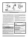 13
13
-
 14
14
-
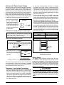 15
15
-
 16
16
-
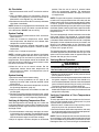 17
17
-
 18
18
-
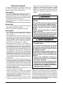 19
19
-
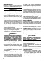 20
20
-
 21
21
-
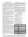 22
22
-
 23
23
-
 24
24
-
 25
25
-
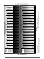 26
26
-
 27
27
-
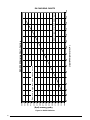 28
28
-
 29
29
-
 30
30
-
 31
31
-
 32
32
-
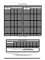 33
33
-
 34
34
-
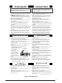 35
35
-
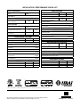 36
36


Unbranded R6GN 12.5 - 15 Ton Installation guide
- Type
- Installation guide
- This manual is also suitable for
Ask a question and I''ll find the answer in the document
Finding information in a document is now easier with AI
in other languages
Related papers
-
Unbranded PPG2GF-A Installation guide
-
-
-
Broan PPG2GF-B Installation guide
-
-
Broan R8GE, Single Phase Installation guide
-
-
-
Broan R6GI User manual
-
Other documents
-
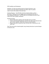 Web WPAD Operating instructions
-
Lennox 15GCSX User manual
-
 GOODMAN Gas Heater GPG13 User manual
-
Reznor R6GD Installation guide
-
Mammoth R8GE, Single Phase Installation guide
-
Reznor R6GP User manual
-
Allied Commercial BV474 Installation, Operation & Maintenance Manual
-
Amana APD14M Owner's manual
-
GOODMAN Heating System PG 15 User manual
-
ICP PDX348120K00A1 Installation guide

