iNSTALLATiON AND SERVICE MUST BE PERFORMED BY A QUALiFiED iNSTALLER.
iMPORTANT: SAVE FOR LOCAL ELECTRICAL iNSPECTOR'S USE.
READ AND SAVE THESE iNSTRUCTiONS FOR FUTURE REFERENCE.
_r_ If the information in this manual is not followed exactly, a fire or explosion may result
causing property damage, personal injury or death.
FOR YOUR SAFETY:
-- Do not store or use gasoline or other flammable vapors and liquids in
the vicinity of this or any other appliance.
-- WHAT TO DO IF YOU SMELL GAS:
• Do not try to light any appliance.
• Do not touch any electrical switch; do not use any phone in your building.
• Immediately call your gas supplier from a neighbor's phone.
Follow the gas supplier's instructions.
• If you cannot reach your gas supplier, call the fire department.
-- Installation and service must be performed by a qualified installer,
service agency orthe gas supplier.
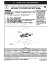
30" Min. *
(76.2 cm)
C
Gas Cooktop
Dimensions
Gas Cooktop
Cutout Dimensions
Figure I
30"GasCooktop
36"GasCooktop
30(76,2)
36(91,4)
21Y4(55,2)
21Y4(55,2)
4 h (10,8)
4 V4(10,8)
27 (68,6)
33 1/4(84,5)
19 (48,3)
19 (48,3)
30"GasCooktop 27 1/4(69,2) 28 1/2(72,4) 19_/8(48,6) 193/4(50,2) 8 (20,3)
36"GasCooktop 33 7/8(86,1) 34 1/4(87) 19_/8(48,6) 193/4(50,2) 8 (20,3)
All dimensions are stated in inches and (cm).
DimensionH includesa 5" (12,7 cm) spaceunderneaththe cooktop for connectionto gassupplyline.
NOTE: Wiring diagrams for this cooktop are enclosed in this booklet
Printedin China
318205458 (1307) Rev.A
English - pages 1-9
Espaflol - p_iginas 10-18
Fran_ais - pages 19-27
Wiring Diagram 28

important Notes to the Installer
1. Read all instructions contained in these installation
instructions before installing the cooktop.
2. Remove all packing material before connecting the
electrical supply to the cooktop.
3. Observe all governing codes and ordinances.
4. Besure to leave these instructions with the consumer.
5. Note: For operation at 2000 ft. elevations above see
level, appliance rating shall be reduced by 4 percent
for each additional 1000 ft.
important Note to the Consumer
Keep these instructions with your Use and Care Guide for
future reference.
IMPORTANT SAFETY
INSTRUCTION
Installation of this cooktop must conform with local
codes or, in the absence of local codes, with the National
Fuel Gas Code ANSI Z223.1/NFPA 54 in the United
States, or in Canada, with the Canadian Fuel Gas Code,
CAN/CGA B149 and CAN/CGA B149.2.
• When installed in a manufactured (mobile) home
installation must conform with the Manufactured
Home Construction and Safety Standard, title 24 CFR,
part 3280 [Formerly the Federal Standard for Mobile
Home Construction and Safety, title 24, HUD (part
280)] or, when such standard is not applicable, the
Standard for Manufactured Home Installation, ANSI/
NCSBCSA225.1 or with local codes where applicable.
This cooktop has been design certified by CSA
International. As with any appliance using gas and
generating heat, there are certain safety precautions you
should follow. You will find them in the Use and Care
Guide., read it carefully.
• Air curtain or other overhead hoods, which operate
by blowing a downward air flow on to a range, shall
not be used in conjunction with gas ranges other
than when the hood and range have been designed,
tested and listen by an independent test laboratory
for use in combination with each other,
Be sure your cooktop is installed and grounded
properly by a qualified installer or service
technician.
This cooktop must be electrically grounded in
accordance with local codes or, in their absence,
with the National Electrical Code ANSI/NFPA
No. 70--latest edition in the United States, or in
Canada, with the Canadian Electrical Code, CSA
C22.1 Part 1.
The burners can be lit manually during an
electrical power outage. To light a burner, hold a
lit match to the burner head, then slowly turn the
Surface Control knob to LITE. Use caution when
lighting burners manually.
Do not store items of interest to children in
cabinets above the cooktop. Children could be
seriously burned climbing on the cooktop to reach
items.
To eliminate the need to reach over the surface
burners, cabinet storage space above the burners
should be avoided.
Adjust surface burner flame size so it does not
extend beyond the edge of the cooking utensil.
Excessiveflame is hazardous.
Never use your cooktop for warming or heating
the room, Prolonged use of the cooktop without
adequate ventilation can be hazardous.
Do not store or use gasoline or other flammable
vapors and liquids near this or any other
appliance, Explosions or fires could result.
The electrical power to the cooktop
must be shut off while gas line connections are
being made. Failure to do so could result in serious
injury or death.

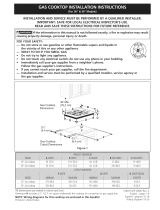
13" (33cm)
Max.Depth
ForCabinet
InstalledAbove
Cooktop.
18"Min.
(45,7cm)
B MinimumDistanceBetween
RearEdgeofCutoutandNearest
CombustibleSurfaceAbove
Countertop.
24"(6!cm)
--T!
Clearance
C
30" (76,2 cm)
Min. Clearance
Between
the Top of
the Cooking
Platform and
Unprotected
Wood or Metal
Cabinet
To eliminate
the risk of burns or fire from
reaching over heated surfaces,
cabinet storage space located
above the cooktop should be
avoided. If cabinet storage is
provided, risk can be reduced
by installing a range hood
that projects horizontally a
minimum of 5" (12,7 cm)
beyond the bottom of the
cabinets.
Allow a minimum of 61/2"(16,5 cm) below
the countertop for drawer. Make sure
there will be no interference with gas or
electrical connection.
30" Cooktop
36" Cooktop
30"(76,2cm)
36"(91,4cm)
a ::
2Y2"(6,4cm)
23/4"(7cm)
aii ft
ia
9"(22,9cm)
9"(22,9cm)
Figure 2 - CABINET DESIGN
3

Typical Under
Oven
Counter Installation of an Electric Built-in
with a Cooktop Mounted Above
All mounting hardware must be
used to secure the built-in oven to
the cabinets. Refer to the built-in
oven installation instructions.
Junction box must
be located approx.
3" (7,6 cm) to the
left of the built-in
oven cutout.
This cooktop may be
installed over certain
built-in electric oven
models.
Side filler panels are necessary to isolate
the unit from adjoining cabinets. Panel
height should allow for installation of
approved cooktop models. See "Typical
GasCooktop Installation Over an
Electric Built-in Oven Installed Under the
Counter" on next page.
208/240 Volt
grounded junction
box for built-in oven.
Cut an opening in wood base minimum 4"
(10,2 cm) x 4" (10,2 cm) to route armored
cable to junction box.
Unit will
overlap
cutout
(minimum)
edges by
1" (2.5cm)
36 "
(91,4 cm)
Min.
Use 3/4" (1,9 cm)
plywood, installed on
two runners, flush with
toe plate. Base must be
capable of supporting
150 pounds (68 kg) for
27" models and 200
pounds (90 kg) for 30"
models.
4 1/2" (11,4 cm)
Max.*
If no cooktop is installed
directly over the oven unit,
5" (12,7 cm) maximum is
allowed.
E F
OVENSIZE
Min. Max. Min. I Max.
30" 27 ¼" 28 ¼" 28 F2" 29" 23 F2"
(76,2 cm) (69,2cm) (71,8 cm) (72,4cm) (73,7cm) (59,7 cm)
27" 27 ¼" 28 ¼" 24 %" 25 ¼" 23 F2"
(68,6 cm) (69,2cm) (71,8 cm) (63,2cm) (64,1cm) (59,7 cm)
Figure 3

Typical Gas Cooktop Installation Over an Electric Built-in
Oven Installed Under the Counter
Manifold Pi
Flexible Connector
I I18" (45,7 cm) Max.-----_ I
I
Wall Oven Cabinet
IFlare
Union
Cabinet sides or
filler panel
61/2 "
5 cm)(16,5 cm)
(12,7 Min.
Flare
Union
120V/6OHz
Grounded
Outlet
Pressure
Regulator
Manual Shutoff Valve
(Tobe accessible
for shut-off valve
÷
4" (10,2 cm)
Right Side
of Cabinet
operation)
r "" k' I
,-, uoo _op
Front
Wall Oven
Side view
Figure 4

Wall Outlet Location
, 12,,_
;
I 10"
i
I Recommended area for |
120Vgrounded outlet |
i on rear wall.
/
t_oFRu_N_ET 22 "
',NOTE: If an outlet
I is not available, I
have one installed by
i a qualified technician,
tt OF UNIT
Figure 5
Cooktop Installation
1. Visually inspect the cooktop for damage.
2. Set the cooktop into the countertop cutout.
NOTE: Do not use caulking compound; cooktop should
be removable for service when needed.
To clamp down, insert an angle bracket into the slot
on each side of the unit as shown. Run thumb screw
up through the bracket, up against the bottom of the
counter. Tighten until the unit draws down and is secure.
Provide an Adequate Gas Supply
This cooktop is designed to operate on natural gas at 4"
of manifold pressure only.
A pressure regulator is connected in series with the
manifold on the cooktop and must remain in series with
the supply line.
For proper operation, the maximum inlet pressure
to the regulator must be no more than 14" of water
column (W.C.) pressure.
For checking the regulator, the inlet pressure must be at
least 1" (or 2,5 kPa) greater than the regulator manifold
pressure setting. The regulator is set for 4" of manifold
pressure, the inlet pressure must be at least 5".
The gas supply line to the range should be 1/2" or 3/4"
pipe.
LP/Propane Gas Conversion
This appliance can be used with Natural gas or LP/
Propane gas. It is shipped from the factory for use with
natural gas.
A kit for converting to LPgas is supplied with your
cooktop. The kit is marked "FOR LP/PROPANEGAS
CONVERSION".
Granite countertop Installation Kit
A Granite Countertop Installation kit # 903103-9010 can
be ordered through a Service Center or by phone at 1-877-
ELECTROLUX (1-877-435-3287).
Clamp Down Information
Once the cooktop is installed in the counter opening,
you must clamp the unit down as shown.
Cooktop
I
Angle
Bracket14"/
Seal
Countertop
Figure 6
Thumb
Screw
The conversion must be performed by a qualified service
technician in accordance with the kit instructions and
all local codes and requirements. Failure to follow
instructions could result in serious injury or property
damage. The qualified agency performing this work
assumes responsibility for the conversion.
Failure to make the appropriate
conversion can result in serious personal injury and
property damage.
Important: Remove all packing material and literature
from cooktop before connecting gas and electrical
supply to cooktop.

Install Pressure Regulator
Install the pressure regulator with the arrow on the
regulator pointing up toward the unit in a position
where you can reach the access cap.
Do not make the connection too tight.
The regulator is die cast. Overtightening may crack the
regulator resulting in a gas leak and possible fire or
explosion.
Manual GAS FLOW Pressure
Shutoff Flare _1_ Flare Regulator
Valve Union Union
On, ltr/ t t ....
Nipple Flexible Nipple
Access
Off Connector
Cap
All connections must be wrench-tightened
Figure 7
Assemble the flexible connector from the gas supply pipe
to the pressure regulator in the following order:
1. manual shutoff valve
2. 1/2" (1.3 cm) nipple
3. 1/2" (1.3 cm) flare union adapter
4. flexible connector
5. 1/2" (1.3 cm) flare union adapter
6. 1/2" (1.3 cm) nipple
7. pressure regulator
Use pipe-joint compound made for use with Natural and
LP/Propane gas to seal all gas connections. If flexible
connectors are used, be certain connectors are not
kinked.
The supply line must be equipped with an approved
manual shutoff valve. This valve should be located in the
same room as the cooktop and should be in a location
that allows ease of opening and closing. Do not block
access to the shutoff valve. The valve isfor turning on or
shutting off gas to the appliance.
Shutoff Valve -
Open position
Figure 8
Once regulator is in place, open the shutoff valve in the
gas supply line. Wait a few minutes for gas to move
through the gas line.
Check for leaks. After connecting the cooktop to the
gas supply, check the system for leaks with a manometer.
if a manometer is not available, turn on the gas supply
and use a liquid leak detector (or soap and water) at all
joints and connections to check for leaks.
Do not use a flame to check for leaks
from gas connections. Checking for leaks with a flame
may result in a fire or explosion.
Tighten all connections if necessary to prevent gas
leakage in the cooktop or supply line.
Check alignment of control knob valves after
connecting the cooktop to the gas supply to be sure the
cooktop manifold pipe has not moved. A misalignment
could cause the valve stems to rub on the control panel,
resulting in a gas leak at the valve.
Disconnect this cooktop and its individual manual
shutoff valve from the gas supply piping system during
any pressure testing of that system at test pressures
greater than 1/2 psig (3.5 kPa or 14" water column).
Isolate the cooktop from the gas supply piping
system by closing its individual manual shutoff valve
during any pressure testing of the gas supply piping
system at test pressures equal to or less than 1/2 psig
(3.5 kPa or 14" water column).
Electrical Requirements
120 volt, 60 Hertz, properly grounded branch circuit
protected by a 15 amp circuit breaker or time delay fuse.
Do not use an extension cord with this cooktop,
Grounding Instructions
IMPORTANT Pleaseread carefully.
For personal safety, this appliance must be properly
grounded,
The power cord of this appliance isequipped with a
3-prong (grounding) plug which mates with a standard
3-prong grounding wall receptacle (see Figure 9) to
minimize the possibility of electric shock hazard from the
appliance.
The wall receptacle and circuit should be checked by
a qualified electrician to make sure the receptacle is
properly grounded.
Where a standard 2-prong wall receptacle is installed,
it is the personal responsibility and obligation of the
consumer to have it replaced by a properly grounded
3-prong wall receptacle.
7

Donot,underanycircumstances,cutor removethe
third (ground)prongfromthepowercord,
Disconnectelectricalsupplycordfrom
wallreceptaclebeforeservicingcooktop.
Preferred Method
Grounding type
wall receptacle
not, under any
circumstances, cut,
remove, or bypass
the grounding
prong,
note that the burner heads are secured to the cooktop.
The cooktop is not removable. Do not attempt to remove
or lift the cooktop.
_To prevent flare-ups and avoid creation
of harmful by-products, do not use the cooktop without
all burner caps properly installed to insure proper ignition
and gas flame size.
Always keep the burner caps and burner grates in place
whenever the surface burners are in use. DO not allow
spills, food, cleaning agents or any other material to
enter the gas orifice holder openings.
Power supply cord with
3-prong grounding plug.
Figure 9
Model and Serial Number Location
The serial plate is located on the underside of the
cooktop (see Figure 10).
When ordering parts for or making inquires about your
range, always be sure to include the model and serial
numbers and a lot number or letter from the serial plate
of your cooktop.
Your serial plate also tells you the rating of the burners,
the type of fuel and the pressure the cooktop was
adjusted for when it left the factory.
Check and be sure the size of each burner cap matches
the size of the burner head. Check and be sure that all
round style burner caps are correctly in place on round
burner heads.
Check and be sure that all oval style burner caps are
correctly in place on oval burner heads (if equipped).
Check and be sure that all dual or twin style burner caps
are correctly in place on dual or twin heads (if equipped).
On round style burners, the burner cap lip (Figure 11)
should fit snug into the center of burner head and be
level. Refer to figures 12 & 13 for correct and incorrect
burner cap placement.
Once in place, you may check the fit by gently sliding
the burner cap from side to side (Figure 14) to be sure it
is centered and firmly seated. When the burner cap lip
makes contact inside the center of the burner head you
will be able to hear the burner cap click. Pleasenote that
the burner cap should NOT move off the center of the
burner head when sliding from side to side.
Serial plate is
located under
the burner box.
Figure 10
Check Operation
Refer to the Use and Care Guide packaged with the
appliance for operating instructions and for care and
cleaning of your cooktop.
Do not touch the burners. They may be
hot enough to cause burns.
1, Check Burner Cap Placement
Regular burner
It is very important to be sure that all surface burner
caps and burner grates are properly installed and in the
correct locations before operating the appliance. Please
Burner _ _x,,, Burner
Head
Cap Lip
Fig, 11
Correct Incorrect
Burner Cap Burner Cap
Placement Placement
Fig. 12 Fig. 13

Fig,14
DualFlameburner(If equipped)
RemovealltapesfromburnercapBesurethatthedual
flameburnercapsarecorrectlyplacedBEFOREusing
yourcooktop.
Note:Therearenoburneradjustmentsnecessaryonthis
cooktop.
4.Adjustthe"LOW"Settingof SurfaceBurnerValves
(linearflow)
TesttoverifyifLOWsettingshouldbeadjusted:
a. PushinandturncontroltoLITEuntilburnerignites.
b. Push in and quickly turn knob to lowest position.
c. If burner goes out, reset control to OFF.
d. Remove the surface burner control knob.
e. Insert a thin-bladed screwdriver into the hollow valve
stem and engage the slotted screw inside. Flame size
can be increased or decreased with the turn of screw.
Turn counterclockwise to increase flame size. Turn
clockwise to decrease flame size (Figure 16).
Adjust flame until you can quickly turn knob from
LITEto lowest position without extinguishing the
flame. Flame should be as small as possible without
extinguishing.
Burner
Burner Simmer
Precision Flame
Figure 15
Burner
Head
2. Turn on Electrical Power and Open Main Shutoff
Gas Valve
3. Check the Igniters
Operation of electric igniters should be checked after
range and supply line connectors have been carefully
checked for leaks and range has been connected to
electric power.
a. To check for proper lighting, push in and turn a surface
burner knob to the LITE position. You will hear the
igniter sparking.
b. The surface burner should ignite when gas is available to
the burner. Purge air from supply lines by leaving knob
in the LITE position until burner ignites. Each burner
should light within four (4) seconds in normal operation
after air has been purged from supply lines.
c. Visually check that burner has a flame, Once the
burner ignites, the control knob should be turned out
of the LITEposition.
d. Try each surface control knob separately until all
burner valves have been checked. Each burner
location is equipped with a separate electrode.
Valve
Stem
Figure 16
When All Hookups are Complete
Make sure all controls are left in the OFFposition.
Make sure the flow of combustion and ventilation air to
the cooktop is unobstructed.
Before You Call for Service
Read the Before You Call for Service Checklist and
operating instructions in your Use and Care Guide.
It may save you time and expense. The list includes
common occurrences that are not the result of defective
workmanship or materials in this appliance.
Refer to the warranty in your Use and Care Guide for
our service phone number and address, Pleasecall or
write if you have inquiries about your product and/or
need to order parts,
9
Page is loading ...
Page is loading ...
Page is loading ...
Page is loading ...
Page is loading ...
Page is loading ...
Page is loading ...
Page is loading ...
Page is loading ...
Page is loading ...
Page is loading ...
Page is loading ...
Page is loading ...

Tubeenm_talflexible
conduitd'alimentationengaz
MurdeI'armoiregauche
oumurdes_paration
Armoire
5" Max.
18"Max.
(45,7cm) _'
I
6 1/2"Min.
5 cm)
Manchon
_vas_
Prisede
120V/6OHz
mise _ la terre
R_gulateur
de pression
4" (10,2 cm)
i
Mur de
droite de
I'armoire
Robinet d'arr_t manuel
(l'acc_s au robinet d'arr_t
dolt _tre facile)
TABLE DE CUISSON A GAZ
-\,
\ ...........................................................................................................................................................................................................J
Vue de face
Vue de c6te du
four encastre
Figure 4- INSTALLATION TYPIQUE D'UNE TABLE DE CUISSON A GAZ AU-DESSUS D'UN FOUR ENCASTRt_
leLECTRIQUE INSTALLIe SOUS LE COMPTOIR
23
Page is loading ...
Page is loading ...
Page is loading ...
Page is loading ...

roP BU_N'=R ]GNI rER
OPT I ONA[
aUEM,_CORDE ENCEND_DO SLr'ER_rJ_
0PC IONAL
Boua _E D' ALLUM,qGE_ULEU_
TOP 8UrgER IGN]TF'R
apT ] ONAL
QUEMADOROE ENCENOlO0 SUPERIOR
OPC] ONAL
BOUa IE D"ALLC_A_-BRULEUR
TOP BURNER IGNITER
CUEMAD0_ DE ENCEN43100 SUPERIOR
BOUG]E D'ALLUHAGE_RULEUR
TOP BURNER IGNITER
QUEMAUOR DE ENCE_3JOO SLJt_ER_OR
BOUG_E D'ALLUMAGE _ULEUR
E-
F
BKI _ m<_,
Z
RIGHT REAR
_GNS_
INrEb, E:TRASERO
DEREC_D
_N_ER _LLUM
D AR
LEF_ REA_
IGN S_
INT _NC TRASERO
IZ_J_ERO0
INTERALLU_
GAR
lEFT FRONT
JGN SW
]NT ENC DE
FREN_E _ZOU_ERBO
]NTERALLUM
GAY
E i_]c_d_ _RONr
IGNSW
FRENTE OERECHQ
R O INTERRLLUM
DAV
BK E
CONNECF_:_
EmPALME
CCNNECTEUR
GnOUNO
PUESrA A TICRnA
MISE A LA TERn8
PARA TRANSPORTE
W_N Nr DE F_RZA
DISCONNECT POWER BEFORE SERVICING UNiT CABLE
O "ALIHENrA_[ON
DESCONECTE LA ENERG_A ANTES DE REALIZAR
_L MANTENIMIENTO DEL ELECTRQOOMEST_CO
AVFRTISSEMENT
_RANT AVANT D'EFFECTUER LA
REPARA11ON
...._ BLACK 7 _7 _:iSF_.............................................................................................................
...............2..... .......
CAUTION:
LABEL ALL WIRES PRIOR TO D]SCONNECTION WHEN SERVICING C0NT_OLS
#IRING ERROR CAN CAUSE IMF_ROPER A]x_J DANGEROUS OPERATION
VERIly pROPER OPERATION AFIER SERVICING
AV_SO:
ET[QUETE TOD_ LOS ALAP!B,qES ANTES DE OESCONI CTAR PAR
REAL_ZAR El MANT_NIM_EN]O DE LDS CONIROLES ER_)R DE
IILAMB_A_ PUEOE CAUSAR UN PUNC [ONAMIENTO INCOR_ECTO
Y PELIGR_SO VERIOUE $1 EL FUNC[ONAM_ENTO ESTA
CORRECTO DESPUES DEL MANTEN_MIENTD
AVE_T!#SQMQH!_
ET[QUETER CHAQUE FJL AVANT LE DEBRANCHEMENT DE CEUX_C[ UNE ERRbL_q DE
BRANCHEMENT _UT CAU_R UNE OPERATION DANGP_USE VEmFIER LE BOW
FONC_IO_E_NI a_ L'_:'F:'A_EJL _PRES rOUTE REPARATION
RIGHT FREJNT _EFT FRONT
_GNS_ IbN SW
_NT ENID DE _NTENC DE
PREN]E OERECHO P_EN_E _Z_IE_DO
INTERAttUM _NTERALLUM
DAV G AV
[EFT _AR RIGHT REAR
ION SW [GN S_
INT E_:TRASERO [NT_NCTRA_RO
[ZOUIERO0 DERECH0
[NTERALLUM INTE_ALLUM
G AR D AR
TOP BURNER IGNITER
QUEMAOOQ DE ENCENDIDO SU_RIOR
BOUGIE D'ALLUMAGE _RULEU_ _
lOP BURNER IGN[]ER
OUEMADO_ [IE ENCENQIDO SUgERIOR
BC_GIE O'ALLUMnGE _R_EUR _ _>
TOP BURNER IGNITER
OUEMADOR LYE ENCENDIOO SUPERIOR
_UGIE D_ALLL,PIAOE_BRL_EUR _ ...................................
TOP BURNIR _GN[TER
OUENADOR DE ENC_ND]OO SUPERIOR
$18047111 REV.B
TOP F_( RN R IGNI T R
OUEMADOR DE ENCE_[DO SUER OR
II]]/
TOP [RN R ]GN T R
OU['MADOR DE ENCEND DO SUPERIOR
OP BURN_:R ION]lEA _I_I!
OU _ADOR DE ENCENDI©O SUFER]OR
BOUC IE D"ALL_AaE _ULEUR
TOP BURNER GN[TER
QUEMADOR C_ ENCENDIDO SLJPE qI OR
L
t _4[GHI IREA_
]GN sw
]N[ ENC IRAS RO
U_REC _:)
]N_ER ALLUM
D AR
R_
I LE_¸1 R_AR
6N SW
I_T ENC TRASERO
ZQU_EAP£_
_NIER A_UM
G A_
I EFT FRONT
_GN SW
_NI ENC DE
iNTER _ LUM
U RIGHT FRO_T
GN S_
F_NT_ DERECHO
_NTER A _
CENtrE RE£R
IaN SW
INT _NC CENT_O
IN _ER ALLUM
C /_R
ION TER MODUL£ BOARD r_-- CONNEC OR
CUADRO DE HODULO DE ENCEN©IDO
80C X)NNC _C)N AlUM I# MpA PI
CONN_ CTE_ JR
UROUNb
W/_:_N _ NG UESTA A T [ ERdA
)IS[ON_'CI ROW R E OR SE_V CING t,N MISE A LA TERRE
rWlSO
Y{/C@q:t A NRGIA AN_', I) RA IZAR
I MANTENll _ NTO F) I ECTRODO[_ _T ICO POWE_ CO_D
DlSCON_CT POb/ER @EFORE SERV ClNG _ T PARA TRANSPO_TE
AVERT 1SSE_NT DE FUERZA
_L_E_ EE _OORANT AVANT D'EFFEFTUER LA CABLE
E_ARAT [ ON D" AL] MENTAT O_X _
4 .........20 5o" c . :'iS2 ....
L1
CAUTION:
LABEL ALL W _S PRIOR TO D_SCONNECT_ON WHEN SERV C]NG CONTROLS
g2IR]NG ERROR CAN CAUSE M_ROR R AN{:} DA%_DEROUS OPERAT ON
VERIFY PROPER OP RATI{;N AFTER SERVICING
AvlsO:
Er Qur_ For)@, I0'1 At AMF_Rr S ANTq D f?I_CON_C1AR PA_
_/xt ZaR _ MANr NIM NO D OS ;ONIR(X R_OR )
/X /_,M_9_/_,J PLJ _) CAJ_/Vq UN f'LJNCIONA NIO INCOR_R CrO
Y PLI{)ROSOV R(? SI L _UNCIONA N[O S X
:o_r? era os,_s _-L MaN_N MIN
AVERT I S_MENT :
ET QUETER CHAQUE FIL AVANT LE DEBRANC IEMENT DE CEUX C UNE ERREUR Ct-
_ANC EMENT _UT CAUSER U_ O_ERATJON ©ANGEREUSE VER FIER LE B©N
FONCTIONNEMENT DE L'APpAREIL ApRES TOUTE REpARAT ON
....!............................!_!_!?£:E 2_£J EJ2E2 (E2L?(.22_1s_........................................
SAGE UI STYLE COLOR CODE / C@ aDS DE COLOr_ /
_]_BRE )lT)# TEMP _C HOOD O
CN/R R AR R IGI4T FRONT LEFT FRONT _ EFT REAR alGHT I_EA_,_
]GNSW _ON SW ION SW laNS_ IONS_
INT ENC CENTRO _NI¸ ENC _ INr _N_: 0£ INT ENC II_ASERO _NT ENC TRABERO
IRASEnO F_N1E D_RECHO _NTE IZQUJERC_a IZOUIERDO OERECHO
INTER ALLUH _NTER ALUM¸ ]NTE_ ALLUM INTER ALLUM _NrER _LL_ml
C AR E) fW _ AV G A_ D _R
fOP BtJRNFR IONIfER
QLJ MADOR DE _NC N{J :£} SUP{:RI(_ -J
BO'£:; E )" AL i t;HAG BAMLEUR
OTE :
r_ RV IC : IF _ _1 /xr:r h4 :N [ O _[_1 NA r} H C(}M[:<> N_ C ::35AIRY, ;OMPARA _ r W I_ I YPE AND
GAGE AND COMPARABLE TERM1 ALS MUST BE USED
_OT A :
_ C_I_SO QUE A NECESAR O DE RE M_ AZA_ EOS B(_NES. ES _CESAIRIO DE UF _ [ZAR
EL MlSMO T PO DE ALAMEJRE Y DE t4EDI©OR Y EL MOMO TIPO DE 8ORNES
NOE :
_Y_'iCE:SI DES F]LS OU DES COSSES DO VENT ETRE REMTSLACES UT_L]SEZ DES PIECES
CA IBA_ E1 DE TYPES EQ IVA :N/S
318047112 REV.A
N
28
/