Page is loading ...

MITSUBISHI
THE BIG SCREENCOMPANY TM

RISK OF ELECTRIC SHOCK
DO NOT OPEN
CAUTION:
TO REDUCE THE RISK OF ELECTRIC SHOCK,
DO NOT REMOVE COVER (OR BACK).
NO USED SERVICEABLE PARTS INSIDE.
REFER SERVICING TO QUALIFIED SERVICE PERSONNEL
/_The lightning flash with arrowhead symbol within an equilateral triangle is intended to alert theuser of the presence of uninsulated "dangerous voltage" within the product's enclosure that
may be sufficient magnitude to constitute a risk of electric shock.
The exclamation point within an equilateral triangle is intended to alert the user to the
presence of important operating and maintenance (servicing) instructions in the literature
\accompanying the appliance.
Warning: To avoid permanently imprinting a fixed image onto your TV screen, please do not display the
same stationary images on the screen for more that 15% of your total TV viewing in one week. Examples
of stationary images are letterbox top/bottom bars from DVD disk or other video sources, side bars when
showing standard TV pictures on widescreen TV's, stock market reports, video game patterns, station
Iogos, web sites or stationary computer images. Such patterns can unevenly age the picture tubes causing
3ermanent damage to the TV. Please see pages 23 and 68 for a detailed explanation.
Note: This equipment has been tested and found to comply with the limits for a Class B digital device,
pursuant to part 15 of the FCC Rules. These limits are designed to provide reasonable protection
against harmful interference in a residential installation. This equipment generates, uses and can radiate
radio frequency energy and, if not installed and used in accordance with the instructions, may cause
harmful interference to radio communications. However, there is no guarantee that interference will not
occur in a particular installation. If this equipment does cause harmful interference to radio or television
reception, which can be determined by turning the equipment off and on, the user is encouraged to try
to correct the interference by one or more of the following measures:
• Reorient or relocate the receiving antenna.
• Increase the separation between the equipment and the receiver.
• Connect the equipment into an outlet on a circuit different from that to which the receiver is
connected.
• Consult the dealer or an experienced radio/TV technician for help.
Changes or modifications not expressly approved by Mitsubishi could void the user's authority to operate
this equipment.
WARNING:
TO REDUCE THE RISK OF FIRE OR ELECTRIC SHOCK, DO NOT EXPOSE THIS APPLIANCE TO RAIN
OR MOISTURE.
CAUTION:
TO PREVENT ELECTRIC SHOCK, MATCH WIDE BLADE OF PLUG TO WIDE SLOT, FULLY INSERT.
NOTE TO CATV SYSTEM INSTALLER:
THIS REMINDER IS PROVIDED TO CALL THE CATV SYSTEM INSTALLER'S ATTENTION TO ARTICLE
820-40 OF THE NEC THAT PROVIDES GUIDELINES FOR THE PROPER GROUNDING AND, IN PAR-
TICULAR, SPECIFIES THAT THE CABLE GROUND SHALL BE CONNECTED TO THE GROUNDING
SYSTEM OF THE BUILDING, AS CLOSE TO THE POINT OF CABLE ENTRY AS PRACTICAL.

Table of Contents
MPORTANT SAFEGUARDS ............................................................................ 4-5
_.ppendix A: Bypassing the V-Chip Lock ........................................................................................................... 59
_.ppendix B: High De d tim Input sConnect im Corrp at il_ lity ....................................................................... 61
_.ppendix C: Remote Control Programing Codes ............................................................................................. 62
_.ppendix D: Cleaning and Service ..................................................................................................................... 63
_.ppendix E: Troubleshooting .............................................................................................................................. 64
ndex ................................................................................................................................................................. 65-66
_itsubishi Projection TV Limited Warranty ....................................................................................................... 67

1.
=
3.
Read, Retain and Follow All Instructions
Read all safety and operating instructions before operating the TV. Retain the safety and operating instructions
for future reference. Follow all operating and use instructions.
Heed Warnings
Adhere to all warnings on the appliance and in the operating instructions.
Cleaning
Unplug the TV from the walt outlet before cleaning. Do not use liquid, abrasive, or aerosol cleaners. Cleaners
can permanently damage the cabinet and screen. Use a lightly dampened cloth for cleaning.
4, Attachments and Equipment
Never add any attachments and/or equipment without approval of the manufacturer as such additions may
result in the risk of r_ d e_tricshock or ct her personal ir_u_y.
5, Water and Moisture
Do not use the TV where contact with or immersion in water is possible. Do not use near bath tubs, wash
bowls, kitchen sinks, laundry tubs, swimming pools, etc.
6. Accessories
Do not place the TV on an unstable cart, stand, tripod, or table. The TV may fall, causing
serious injury to a child or adult and serious damage to the TV. Use only with a cart, stand,
tripod, bracket, or table recommended by the manufacturer, or sold with the TV. Any mounting
of the TV should follow the manufacturer's instructions, and should use mounting accessories
recommended by the manufacturer.
An appliance and cart combination should be moved with care. Quick stops, excessive force,
and uneven surfaces may cause the appliance and cart combination to overturn.
=
Ventilation
Slots and openings in the cabinet are provided for ventilation and to ensure reliable operation of the TV and
to protect it from overheating. Do not block these openings or allow them to be obstructed by placing the TV
on a bed, sofa, rug, or other similar surface. Nor should it be placed over a radiator or heat register. If the
TV is to be placed in a rack or bookcase, ensure that there is adequate ventilation and that the manufacturer's
instructions have been adhered to.
8, Power Source
This TV should be operated only from the type of power source indicated on the marking label. If you are not
sure of the type of power supplied to your home, consult your appliance dealer or local power company.
g.
Grounding or Polarization
This TV is equipped with a polarized alternating current line plug having one blade wider than the other. This
plug wilt t irt ot hepower cut I_ ml yone way. If _ouar eunabl et oi r$er t the pl _gf d lyi _ ot heout I_, try
reversing the plug. If the plug should still fail to t, _nt act y_ur d e:t d_ ant or epl _e your d_sol _ eout l_.
not defeat the safety purpose of the polarized plug.
10, Power-Cord Protection
Power-supply cords should be routed so that they are not likely to be walked on or pinched by items placed
upon or against them, paying particular attention to cords at plugs, convenience receptacles, and the point
where they exit from the TV.
11.
Lightning
For added protection for this TV during a lightning storm, or when it is left unattended and unused for long
periods of time, unplug itfrom the wall outlet and disconnect the antenna or cable system. This will prevent
damage to the TV due to lightning and power-line surges.

IMPORTANT SAFEGUARDS Continued
12.
13.
Power Lines
An outside antenna system should not be located in the vicinity of overhead power lines or other electric light
or power circuits, or where it can fall into such power lines or circuits. When installing an outside antenna
system, extreme care should be taken to keep from touching such power lines or circuits as contact with
them might be fatal.
Overloading
Do not overload walt outlets and extension cords as this can result in a risk of reor d e:t dcshock.
14.
15.
16.
17.
Object and Liquid Entry
Never push objects of any kind intothis TV through openings as they may touch dangerous voltage points or
short-out parts that could result in reor d e:t dcshock, h_ver spi 1tli_i dof any ki _ on or i_ ot heTV.
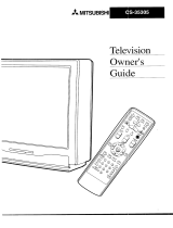
Outdoor Antenna Grounding
If an outside antenna or cable system is connected to the TV, be
sure the antenna or cable system is grounded so as to provide
some protection against voltage surges and built-up static charges.
Section 810 of the National Electric Code, ANSI/NFPA No.
70-1984, provides information with respect to proper grounding of
the mast and supporting structure, grounding of the lead in wire to
an antenna discharge unit, size of grounding conductors, location
of antenna discharge unit, connection to grounding electrodes, and
requirements for the grounding electrode.
EXAMPLE OF ANTENNA GROUNDING
.ANTENNA
(NEC SECTION 810-20)
GROUNDING
CONDUCTORS
}
_GROUND CLAMPS
_POWER SERVICE GROUNDING
ELECTRODE SYSTEM
NEC _-- NATIONAL ELECTRICAL CODE INEC ART 250 PART HI
Servicing
Do not attempt to service this TV yourself as opening or removing covers may expose you to dangerous
voltage or other hazards. Refer all servicing to quail edser vi _ per sonnel.
Damage Requiring Service
Unplug the TV from the wall outlet and refer servicing to quail edser vi _ per sonnel under thef d_l_
conditions:
18.
(a) When the power-supply cord or plug is damaged.
(b) If liquid has been spilled, or objects have fallen into the TV.
(c) If the TV has been exposed to rain or water.
(d) If the TV does not operate normally by following the operating instructions, adjust only those controls that
are covered by the operating instructions as an improper adjustment of other controls may result in damage
and will often require extensive work by a quail edt echni _ ant or est • et heTV t oi tsnor ra 1 q_er_tiun.
(e) If the TV has been dropped or the cabinet has been damaged.
(f) When the TV exhibits a distinct change in performance - this indicates a need for service.
Replacement Parts
When replacement parts are required, be sure the service technician has used replacement parts speci ed
by the manufacturer or have the same characteristics as the original part. Unauthorized substitutions may
resultin r_ de:tdcshockor ether hazards.
19. Safety Check
Upon completion of any service or repair to the TV, ask the service technician to perform safety checks to
determine that the TV is in safe operating condition.
20. Heat
The product should be situated away from heat sources such as radiators, heat registers, stoves, or other
products (including ampli e s) that p"educe heat.


Part I: Thank You
e at Mitsubishi Would Like to Thank You
To the Mitsubishi Consumer:
Thank you for choosing Mitsubishi as your premier home
entertainment partner. Whether this is your rst M tsubi s_i
consumer electronics product or an addition to your growing
Mitsubishi family, you should be proud and delighted for
choosing one of the most technologically advanced bigscreens
available today.
Unlike typical television manufacturers, we have based our
primary design and engineering capabilities in North America
at our California headquarters. As a result, the engineers who
design our television products live in the same communities
as our customers. They know how our customers think and
what their goals and desires are. They know that today's
consumer has never been more sophisticated and that the
way to reach that consumer is to deliver technically advanced
products at prices that our competition simply can't match.
When you look at your new Mitsubishi bigscreen television,
please see all of us who built it, because when we build it, we
see you.
Thank You Again,
The Mitsubishi Team

Partl:Thank You
Unpacking Your New TV
Please take a moment to review the follow-
ing list of items to ensure that you have
received everything included:
[] Remote Control
[] (2) AAA Batteries
[] (3) IR Emitter Cables
[] Product Registration Card
[] Owner's Guide
[] Quick Reference Card
Q®Q ....
QQ
[] Remote Control [] (2) AAA Batteries
[] (3) IR Emitter Cables
Send this
cald in
registeryour
pulchase
Special Features
Your new HD-Upgradeable bigscreen televi-
sion has many special features that make it
the perfect addition to your home entertain-
ment system. Below we have highlighted a
handful.
HD-Upgradeable
With the use of an optional HDTV receiver
like the Mitsubishi SR-HD500 or similar
model, your Mitsubishi bigscreen can dis-
p,ayhighde.U pi Seepages,O, ,.
Wide Screen Picture Format
You will be able to view pictures as the
directors intended you to see them. Both
DTV and DVD's supporting the widescreen
formatwillenableyoutoenjoyatheaterfee,
in the comfort of your home.
Seepages 56-57.
PIP/POPViewing Option
usingPicture-in-PictureandPicture-outside-
Picturewillgiveyouexcitingoptionsforview-
ing yourfavorite programs.
Seepages,,-55.
V-Chip Technology
Mitsubishiunderstandsthatyoumaywantto
shield certain viewersfrom speci cpregran
content. Your Mitsubishi bigscreen will allow
youtorestrictProgrammingbygeneralcon-
tents, speci ccontmts ar e/en by tire.
See pages 36-38.
Multibrand Remote Control
Your Mitsubishi remote control can be pro-
grammed to control many other audio/video
components.
See page 26 & 27.
[] Product Registration Card


Part I1: Installation
Front Control Panel
(M_NO)
S V_EO VIDEO L-AUblO
INPor 4
Figure 1. Front Control Panel.
......Oo
@
ENrEI_ •
u- AbJUSq _
IRIS TM
Intelligent Room Illumination (light) Sensor. Turn this feature on or off using the VIDEO
button on your remote control. When the IRIS is on, your TV will automatically adjust
picture contrast and brightness for the best picture based on your room lighting. When on,
do not block the sensor to ensure an optimum picture.
Pow%,Power (used for Timer function)
During normal operation, the power light will glow steady green when the TV is on, and
not glow when the TV is off. When the TV is set to turn on at a speci cti re, the green
power light will blink while the TV is off. Please see Timer, page 39, for timer setup
instructions.
AN_SE[
@ A/V Reset
Press this button to reset the A/V memory on all eleven inputs to the factory default settings.
Please see A/V Memory Reset, page 42, for instructions.
(MONO)
S VID£O V_DE0 L-AUDIO -_
L ........ J Input 4
This input can be used for convenient connection of a camcorder or other video device to
the TV. Please note that if you connect to the S-VIDEO terminal, the VIDEO terminal is
deactivated. The VIDEO terminal is active when there is no S-Video connection.

Part I1: Installation
Back Panel
mm
@
®
®
B-
®®
®®
® ®®
® ®®
®
®®"
®
®
_R E_TTER HOME THEATER
®®®_
J
[] STB (Set-Top-Box)
This input can be used for the connection of any device with an S-Video output.
[] Inputs 1-3
These inputs can be used for the connection of a VCR, Super VHS (S-VHS) VCR, laser
disc player, or other A/V device to the TV. Please note that if you connect to the S-VIDEO
terminal, the VIDEO terminal is deactivated. The VIDEO terminal is active when there is
no S-Video connection.
[] Output (Monitor and PIP)
The Monitor Output sends the TV audio and video signals, excluding component video,
VGA, or DTV video, to an A/V receiver or other equipment. The PIP output sends the
PIP's or POP's audio signal to an ampli • or wiEI _s headphones. If noPI Por P(]? is
displayed, the PIP output will send the main picture audio signal.
[] Antenna (ANT-A, LOOP OUT, and ANT-B)
ANT-A and ANT-B receive signals from VHF/UHF antennas or a cable system. LOOP OUT
sends the ANT-A signal out to another component, such as a cable box orVCR.
[] IR Emitter Home Theater (System 4 Home Theater IR Control)
Connecting IR emitters here allowthe TV to automaticallychange a digital A/V receiver's
inputina home theater setup, and pass IR commands to other A/V devices.
[] VGA
This inputcan be used for the connectionof a computer. Please see Appendix B, page
61, for signal compatibility.
[] Component Inputs 1-2
These inputs can be used for the connection of A/V equipment with component video
outputs, such as a DVD player. Please see Appendix B, page 61, for signal compatibility.
[] DTV Input
This input is used to connect a DTV receiver, and can be con _r edfar I-DTV corrp orient,
RGB sync on green, and RGB plus H&V. Please see Appendix B, page 61, for signal
compatibility.

Part I1: Installation
How Connections Affect the PIP and POP
To see a picture in the PIP or POP inset, you
may need to select an input source. If the
only input connected is ANT-A, then both oK No_oP ox oK oK oK
the main picture and the PIP/POP insert
OK OK* OK OK OK OK
will be from that input source. If other
video equipment is connected, you may be oK oK oK oK oK oK
able to view these input sources as the oK* oKPoP
PIP/POP insert. When connecting your new oK oK oK Nop_P oK
Mitsubishi bigscreen, it is important to under- V oK oK oK oK oK,* oK
stand which main picture and PIP/POP input oK oK oK oK oK oK,,
sources can and cannot be used together. .............................................
Table 1 shows which inputs can and cannot No_,,_
be used together and the limitations they Table1. *NoSide-by-Sidewiththesame channel.
may require. To see if 480i, DTV 480p, **NoSide-by-Sidewiththesame input.
1080i, Conponent-1 or Component-2 480p is Pip cannotdisplayVGA.
being displayed as the main picture, press
INFO on the TV remote control. The on- _ _* 1
screen display, _r e 1, * II li_ zB0i, zB0p or / DTV3_.**
1080i when those signals are being received. _.. _
See Operation of PIP and POP, pages or
54-55, for operating instructions. An aster- 4:_AM
Tuesday
isk (*) displayed after the signal type indi-
cates that the signal being received is
a non-standard format. A non-standard -- s_9o_,s_e_
format signal may or may not display prop-
Figure 1. On-screen display will show 480i, 480p, or
erly in a PIP/POP inset, lo8oi when those signalsarebeingreceived.
How Connections Affect the System 4 Home Theater IR Control
The Mitsubishi System 4 Home Theater IR to change inputs. You will automatically
Control is a special feature that makes it hear the high quality digital surround sound
easier to use your TV with a digital surround from digital products like your DTV receiver
sound A/V receiver. Once your equipment and DVD player, and high quality analog
is properly connected and set up, your TV stereo or surround sound from non-digital
and digital A/V receiver will change inputs products like your VCR.
together, to match high resolution pictures
with the proper surround sound. Additionally, all IR remote signals from your
Mitsubishi remote or other manufacturers
...........................When you change inputs on your TV to remote will be passed through your TV to
watch different video products, your TV will your A/V devices. Your A/V devices can
send signals via your remote control and the be hidden or behind cabinet doors and con-
infrared emitters to your digital A/V receiver trolled by pointing the remote at the TV.

Part I1: Installation
Special Setups: A/V Equipment (For System 4 Home Theater IR Control)
VCR: Connect the cables to the TV as
directed on page 17, with one exception.
Connect the audio output connection to the
appropriate input on the back of the A/V
receiver (as shown in table 1).
DVD: Connect the cables as directed on
page 19 (using the COMPONENT-1 input),
with one exception. Connect the digital
audio output connection on the DVD player
to the appropriate digital input on the back
of the digital A/V receiver (as shown in table
1).
•Auto Standby: ON (See your A/V receiver's
Owner's Guide for this procedure). For all TV
use, the sound will come from the A/V receiver.
Not available with all A/V receivers.
•Digital Input Assignment for DVD: Assign the
digital input you used for your DVD player to the
A/V receiver's DVD input selector. This proce-
dure is explained in your A/V receiver's Owner's
Guide.
•Digital Assignment for DTV: Assign the digital
input you used for DTV to the A/V receiver's DTV
input selector.
Infrared Emitter: Connect as shown on
page 22.
DTV: Connect the cables as directed on
pages 20-21, with one exception. Connect
the digital audio output connection on the
DTV receiver to the appropriate digital input
on the back of the digital A/V receiver (as
shown in table 1).
A/V Receiver: Connect as directed on
page 18, with two additions. Use a S-Video
cable in step 1 if you have a S-Video VCR.
The TV outputs should be connected to the
A/V receivers input marked TV.
Special Setups: TV
Menu selection for A/V connections, page 32.
•TV Speakers: OFF
•Audio Output: Fixed
•TV Inputs Appropriately Named: See Assign
Input Menu, page 33.
Remote Control, pages 26-27.
•Set the slide switch to the TV position and follow
the programming instructions using the A/V
receiver code appropriate for your A/V receiver,
page 27 (_re5).
Brand Model
The products listed at_he tDp of_his column connectlD _he belowlist_d
inputs on _he back of_he
TV/Cable
appropfiae AN receiver.
SAT/DBS/DTV VCR
DVD
IVHtsubishi M-VRIO00/M-VRSO0 TV VCR2 VCR1 DVD
IVHtsubsihi M-VR£O0/M-VR700 TV CABLE/DBS VCR DVD
Denon AVR2800 TV/DBS VCR2 VCR1 DVD/LD
JVC RX-888V TV VIDEO 2 VCR 1 DVD
Kenwood VR-2080 AV AUX LD VIDEO 1 DVD
Onkyo TX-DS575 VIDEO 3 VIDEO 2 VIDEO 1 DVD
Pioneer VSX-21 TV/SAT VIDEO 2 VCR 1 DVD/LD
Sony STR-DE825 TV/DBS VIDEO 2 VIDEO 1 DVD/LD
Yamaha RX-V2095 TV/DBS VCR 2 VCR1 DVD/LD
Table I. A/V receiver back panel input table

Part I1: Installation
Connecting an Antenna, Wall Outlet Cable, or Cable Box
Separate UHF and VHF Antennas
(Figure 1)
[] Connect the UHF and VHF antenna
leads to the UHF/VHF combiner.
[] Push the combiner onto ANT-A on the
TV back panel.
[] UHF/VHF combiners are not provided
with the TV. They should be available at
most electronic stores.
VHF A_l_lr_ UH_ A_r _la
G _8_GG_i ® g _ _1_
_og_GD _ e_ _m
sa_ Side
Figure 1. Connecting separate UHF and VHF antennas.
Twin Lead Antenna, Coaxial Lead
Antenna, or Wall Outlet Cable
For antenna with twin _t Imds (Fi gpre2)
[] Connect the 300ohm twin leads to the
transformer.
[] Push the 75ohm side of the transformer
onto ANT-A on the TV back panel.
[] 300ohm to 75ohm matching transform-
ers are not provided with the TV. They
should be available at most electronic
stores.
For cable or antenna with coaxial lead (Figure 2)
[] Connect the incoming cable to ANT-A on
the TV back panel.
op_on_l_ot_ _ 7_ohm
Figure 2. Connecting twin lead antenna, coaxial lead
antenna, or wall outlet cable.
TV back paI_l
Cable Box
(Figure 3)
[] Connect the incoming cable to ANT-A on
the TV back panel.
[] Connect two coaxial cables as follows:
[] One from LOOP-OUT on the TV back panel to
IN on the cable box back panel.
[] One from OUT on the cable box back panel to
ANT-B on the TV back panel.
rn_lng
C_ble
[]
TV back pane_
Cable Box
Figure 3. Connecting the cable box.

Part I1: Installation
Connecting a VCR
v bac< p_r
o÷el®_[] o ® e ®1_
_e_l®_ [] o ®e ®E
Antennas or Wall Outlet Cable
(Figure 1)
[] Connect the incoming cable to ANT-A on
the TV back panel.
[] Connect two coaxial cables as follows:
[] One from LOOP-OUT on the TV back panel to
ANTENNA IN on the VCR back panel.
[] One from VCR back panel ANTENNA OUT to
ANT-B on the TV back panel.
[] Now complete gJre3, st_ps 1-2
Figure I. Connecting VCR with antennas or wall outlet
cable.
Cable Box
(Figure 2)
[] Connect the incoming cable to ANT-A on
the TV back panel.
[] Connect three coaxial cables as follows:
[] One from LOOP-OUT on the TV back panel to
IN on the back of the cable box.
[] One from OUT on the back of the cable box to
ANTENNA IN on the VCR back panel.
[] One from ANTENNA OUT on the VCR back
panel to ANT-B on the TV back panel.
[] Now complete gJre3, st_ps 1-2
Composite Video with Audio or
S-Video with Audio
(Figure 3)
Figure 2. Connecting VCR with cable box.
TV b,_k panel
[] Connect a video cable from VIDEO
OUT on the VCR back panel to VIDEO
INPUT-l, INPUT-2 or INPUT-3 on the TV
back panel.
[] If you have a S-VHSVCR, follow the same
steps using the S-Video terminalson the VCR
and TV (in place of the composite terminals).
[] Connect a set of audio cables from
AUDIO OUT on the VCR back panel to
AUDIO INPUT-l, INPUT-2, or INPUT-3
on the TV back panel. The red cable
connects to the R (right) channel and
the white cable connects to the L (left)
channel. If your VCR is mono (non-ste-
reo), connect only the white (left) cable.
Figure 3. Connecting the VCR Audio/Video.

Part I1: Installation
Connecting an Audio Receiver
Stereo Audio System
(Figure 1)
[] Connect the audio cables from AUDIO
MONITOR OUTPUT on the TV back
panel to TV IN or AUX IN terminals on
the back of the audio system. The red
cable connects to the R (right) channel,
and the white cable connects to the L
(left) channel.
[] Turn off the TV's speakers through the
Audio/Video Menu, page 43.
[] Set the audio system's input to the TV
or AUX position to hear the TV's audio
through your stereo system.
TV back #_nel
Figure 1. Connecting the Stereo Audio System
A/V Receiver
(Figure 2)
[] Connect a video cable or S-Video
cable from VIDEO MONITOR OUT on
the back of the A/V receiver to VIDEO
INPUT-1 on the TV back panel.
[] Connect a video cable from VIDEO
MONITOR OUTPUT on the TV back
panel to VIDEO TV IN on the back of
the A/V receiver.
[] Connect a set of audio cables from
AUDIO MONITOR OUTPUT on the TV
back panel to AUDIO TV IN on the back
of the A/V receiver. The red cable con-
nects to the R (right) channel, and the
white cable connects to the L (left) chan-
nel.
Figure 2. Connecting the A/V Receive_

Part I1: Installation
WARNING:
Connecting a DVD Player
TV _s_ _I
_iiil:;ii_"_i_!ii¸
DVD back p,_nel
/
U
Figure I. Connecting the DVD playe_
Connecting an S-Video Device
TV ba_ p_ne_
@@®
Figure 2. Connecting an S-Video Device.
DVD Player with Component Video
(Figure 1)
[] Connect the Component Video cables
from Y/Cr/Cb or Y/Pr/Pb VIDEO OUT
on the back of the DVD player to COM-
PONENT-1 or COMPONENT-2 on the
TV back panel, matching the correct
components:
[] Y to Y
[] CrorPrtoPr
[] CborPbtoPb
[] Connect a set of audio cables from
AUD,OOUTonthebackoftheDVD
player to COMPONENT AUDIO Input 1
or 2 on the TV back panel. The red
cable [] connects to the R (right) chan-
thenel'Land(left)thechannel.whitecable [] connects to
S-Video Device
(Figure 2)
[] Connect an S-Video cable from VIDEO
OUT on the device back panel to VIDEO
INPUT-l, INPUT-2, INPUT-3, or STB on
the TV back panel.
[] Connect a set of audio cables from
AUDIO OUT on the device back panel
to AUDIO INPUT-l, INPUT-2, INPUT-3,
or STB on the TV back panel. The
red cable connects to the R (right) chan .....................................
nel and the white cable connects to
the L (left) channel. If your device
is mono (non-stereo), connect only the
white (left) cable.

Part I1: Installation
Connecting a DTV Receiver
DTV Connectors and Adaptors
(Figure 1)
The TV back panel has 5 RCA-type connec-
tors, for the DTV connection. The back
panel of your DTV receiver may use RCA-
type connectors or BNC-type connectors. If
your DTV receiver comes with BNC type
connections, you will need to purchase BNC
to RCA adaptors to connect the TV to the
DTV receiver. These adaptors should be
available at most electronic supply stores.
BNC _ A r
RCA BNC Find t_
Adapt_r Connec_r Connection
or
Figure 1. DTV connectors and adaptors.
RCA
Connec_r
DTV Receiver with Component
Video Connections
(Figure 2)
........................... ]
[] Connect the outside antenna, cable, or
satellite to ANT, or SATELLITE IN on the
DTV receiver (see your DTV receiver's
owner's guide for instructions, and cable
compatibility).
[] Connect the incoming terrestrial antenna,
or cable (not satellite) to ANT-A on the
TV back panel (a coaxial splitter, avail-
able at most electronic supply stores,
may be required to complete this instal-
lation).
[] Connect the RCA-type cables from the
Y/Pr/Pb outputs on the DTV receiver to
HIGH RESOLUTION INPUT Y/Pr/Pb on
the TV back panel. You may need to set
the DTV input assignment to YPrPb in
the Assign Input menu, page 33.
[] Connect the L (left) and R (right) audio
cables from the DTV receiver to DTV
AUDIO on the TV back panel.
To utilize the bene tsof a di_ ta AN
receiver, connect your DTV receiver's
digital audio out to a digital input on your
digital A/V receiver.
v baca_l_l
_or Cable
Figure 2. Connecting the DTV receiver with component
video connections.
/