Baumer LXG-120M.3D is a high-performance camera for 3D laser triangulation, designed for precise distance measurements in industrial applications. With its advanced laser triangulation technology, the LXG-120M.3D can accurately measure the distance to an object by projecting a laser line onto the surface and analyzing the reflected light.
The LXG-120M.3D offers a resolution of 4096 x 128 pixels, providing detailed images for accurate measurements. Its high frame rate of up to 1326 fps ensures real-time processing, making it ideal for dynamic applications. The camera is also equipped with a powerful FPGA, enabling customization of the image processing algorithms to meet specific application requirements.


-
 1
1
-
 2
2
-
 3
3
-
 4
4
-
 5
5
-
 6
6
-
 7
7
-
 8
8
-
 9
9
-
 10
10
-
 11
11
-
 12
12
-
 13
13
-
 14
14
-
 15
15
-
 16
16
-
 17
17
-
 18
18
-
 19
19
-
 20
20
-
 21
21
-
 22
22
-
 23
23
-
 24
24
-
 25
25
-
 26
26


Baumer LXG-120M.3D User guide
- Type
- User guide
- This manual is also suitable for
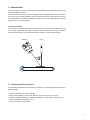
Baumer LXG-120M.3D is a high-performance camera for 3D laser triangulation, designed for precise distance measurements in industrial applications. With its advanced laser triangulation technology, the LXG-120M.3D can accurately measure the distance to an object by projecting a laser line onto the surface and analyzing the reflected light.
The LXG-120M.3D offers a resolution of 4096 x 128 pixels, providing detailed images for accurate measurements. Its high frame rate of up to 1326 fps ensures real-time processing, making it ideal for dynamic applications. The camera is also equipped with a powerful FPGA, enabling customization of the image processing algorithms to meet specific application requirements.
Ask a question and I''ll find the answer in the document
Finding information in a document is now easier with AI
Related papers
-
Baumer LXG-20M.PS User guide
-
Baumer LXG-120M.3D Installation and Operating Instructions
-
Baumer LXG-200C User guide
-
-
-
-
-
Baumer MXGC20c Quick start guide
-
-
Other documents
-
Paasche LXG-14 User manual
-
NGS RED I-SHELL Datasheet
-
-
-
AMS CMV4000 EVALUATION KIT User guide
-
Trixie Alicante User manual
-
 SIMA S.A. HALCON 65 User manual
-
Basler Complete VisualApplets User manual
-
 SIMA S.A. HALCON 125 User manual
-
Sensoray 2255/2257 Software Manual

