Page is loading ...

Fixed and Adjustable Height
Processing Sinks
Installation - Operation - Maintenance - Cleaning
Instruction Manual
PROCESSING SINKS
MAN_0011
2019
© 2019 Bryton Corporation
R
Read and understand all of the instructions and safety
information in this manual before operating this product.

2
Table of Contents
Summary 3
Warnings and Cautions Icon Key 4
Warnings and Cautions When Installing or Operating This Product 5
Processing Sink Models 6
General Specifications 7
Overview of Processing Sink Components 9
Sink Installation 10
Sink Placement Requirements 11
The Pre-Rinse Hot/Cold Water Faucet (H0134-01) 13
Operation and Maintenance of the Pre-Rinse Spray Faucet
21
Assemble and Install Air Gun (PS0900-03)
22
Using and Cleaning the Air Gun 26
Assemble and Install Water Gun (PS0900-06)
27
Safe Use of the Water Gun
33
Cleaning Instructions for the Water Gun
34
The DI Water Faucet (H0132)
35
Air and Water Connections 37
Standard Waste Drain Basket (H0150)
38
Lever Handle Waste Drain (H0142)
39
Drain Pipe Assemblies
40
Foot Levelers (H0090-05-03) and Floor Anchor (S02212-26-PSFA)
44
Assemble Pre-Rinse Faucet Wall Mounts (MM-K50-Y020-Z) 45
Wall Mounting Air and Water Guns Brackets
48
Adjustable Height Sinks Only - Control Panel Technical Data
49
Adjustable Height Sinks Only - Control Panel Setup and Operation
50
Adjustable Height Sinks Only - Maximum/Minimum Height Levels
52
Adjustable Height Sinks Only - Replacing the PCB Enclosure Assembly 53
Sonic Sinks
56
Instructions for Cleaning Stainless Steel Processing Sinks
62
Index
63
Limited Lifetime Warranty
64

3
Instruction Manual
KEEP THIS MANUAL
Summary
DESCRIPTION OF PRODUCT PURPOSE OF THIS MANUAL
This manual covers Processing Sink models:
• Fixed Height Processing Sinks
• Adjustable Height Processing Sinks
• Sonic Sinks
This user manual details the installation, operation,
maintenance and cleaning of the Bryton Corp.
Processing Sinks.
This manual also contains general specifications,
warnings and cautions.

4
Warnings and Cautions Icon Key
The following is a list identifying the various warning and caution icons used in this manual.
Icon Type Icon Description
Warnings (Red triangle with an exclamation point) indicate the
potential for minor to severe injuries up to and including
death to personnel.
Cautions
(Yellow triangle with an exclamation point) indicate
the potential minor injury to personnel and damage to
equipment.
Note: The exclamation point will not be visible where only
equipment damage is present.
Burn Hazard Warnings
(Yellow triangle with radiating lines) indicate a potential burn
injury to personnel.
Electrical Warnings
(Yellow triangle with a lightning bolt) indicate a possible shock
hazard is present.
Severe shock hazards shall be a lightning bolt in a red
triangle.
Explosion Hazard
(Yellow triangle with the explosion icon) indicate the
equipment should not be operated in areas where explosions
could occur.

5
Instruction Manual
Warnings and Cautions When Installing or Operating This Product
Prior to installation or operation, the user must read these warnings and cautions.
The following is a list of the safety precautions, which must be observed when operating this equipment.
WARNINGS indicate the potential for danger to personnel
CAUTIONS indicate the potential for damage to equipment.
These precautions are repeated (in whole or in part), where applicable, throughout the manual. It is
important to review these precautions before using the equipment.
WARNING-INJURY HAZARD -
REPAIRS AND ADJUSTMENTS
should be only attempted by experienced service agents fully
acquainted with this equipment. The use of inexperienced, unqualified persons to service the
equipment, or the installation of unauthorized parts, could cause serious personal injury, or result in costly
damage. Always unplug power cord from power source prior to attempting any repairs or servicing.
WARNING -
DO NOT operate in a potentially explosive atmosphere.
CAUTION-POSSIBLE EQUIPMENT DAMAGE -
When cleaning the sink - See complete Cleaning Instructions in this manual.
• Use a non-abrasive polish.
• Rub in a back and forth motion in the same direction of the surface grain.
NOTE: This product is to be used strictly for the purpose it was designed for. If this product is used in a
manner not specified by Bryton Corp., the protection provided by the equipment may be impaired.
Bryton Corp. disclaims all liability for the consequences of this product being used for purposes other
than its intended design. Product modification or misuse can be dangerous. Bryton Corp. disclaims all
liability for the consequences of product alterations or modifications, as well as for the consequences
which might result from the combination of this product with other products, whether supplied by Bryton
Corp. or by or by other manufacturers, unless such a combination has been specifically endorsed by
Bryton Corp..

6
Processing Sink Models
Available processing sink types are:
• Fixed Height (without hydraulic system)
• Adjustable Height (with hydraulic system)
Both sink types are available in any multiple basin
configuration as required (the standard single, double and
triple basins are shown here).
Sonic sinks are skirted sinks available in fixed or
adjustable height models and for any multiple
basin sink configuration with optional back
mounting frame.
(Sonic Sink shown here with the optional Sonic
Sink Faucet Rack S02211-7519)

7
Instruction Manual
General Specifications
1. Material:
a. Sink basin and sink top: 14 gauge, 300 stainless steel
b. Sink skirt: 18 gauge, 300 stainless steel.
c. Sink shelf: 16 gauge, 300 stainless steel.
d. Sink base tubing: 16 gauge 300 stainless steel.
2. Plumbing detail
a. Fixed height
b. Adjustable height
3. Utility requirements:
a. It shall be the customer’s responsibility to ensure that the incoming water/DI/ air supply meets
manufacturer’s requirements.
b. Cold water: 20 to 50 psi 70°F Max.
c. Hot water: 20 to 50 psi 120°F to 140°F Max.
d. It shall be the customer’s responsibility to ensure (by use of pressure regulators or other means)
that maximum specified pressures are not exceeded.
e. Water lines should be flushed clean before water connections are made.
f. It shall be the customer’s responsibility to ensure that water supplies are properly protected for
internal cross connection control in accordance with local building and plumbing requirements.
g. It shall be the customer’s responsibility to eliminate water hammer conditions should they occur
in the service piping.
h. DI water: flow rate 50 psi – 120 psi, rate operating pressure: 20-125 psi rated operating
temperature: 40-140° F.
i. Air: quick tip air gun complete with five (5) different tips that are quickly changed by a quick
push and pull. Comes with a popular hooked air gun body.
• The rubber tip and the needle tip should be used with 30 psi Max.
• Air hose ¼" I.D. X 10 feet flexcoil retracting air and water, brass fittings with NPT threads (¼"
NPT swivel), low temp -40° to +125°F, high temp -40° to +180°F.
• Vacuum rating is 27"hg @ 72°F. Air inlet deck mount fitting, turret base ⅜" NPT female, single
⅜" NPT female outlet, 3/8" IPS mounting shank with locknut and washer. ⅜" IPS x 2-½" OAL.
• Low-pressure brass threaded pipe fitting ⅜ male x ¼ female pipe size, hex reducing bushing.
4. Power requirements (Adjustable Height Sinks Only):

8
a. 120 Volt, 60 Hz, single phase, 15 amp GFCI protected electrical outlet, installed per local building
codes, and provides protective grounding.
5. Sink is approved ETL/CETL/CSA/NSF recognition.
6. All individual electronic components are UL approved and/or recognized.
General Specifications

9
Instruction Manual
Overview of Processing Sink Components
The processing sink assemblies or components to be installed or programmed are identified in the table
below and will be covered in more detail in this installation manual.
The illustration below shows an adjustable height triple basin sink with all the assemblies as called out in
the table below. Other sinks may have different features than shown here.
Item # Part # Description
1 H0134-01 Pre-Rinse Hot/Cold Water Faucet Assembly
2 PS0900-03 Air Gun Kit
3 PS0900-06 Water Gun Kit
4 H0132 DI Water Faucet
5 H0178-04 Shut-off Valve (Air gun)
6 H0178-05 Shut-off Valve (Water gun)
7 S02212-26-PSFA Floor Anchor
8 PCB-001-ASM PCB Enclosure Assembly

10
Sink Installation
Below is an overview of sink installation steps. Details for the installation of the various parts (steps c-q) will
be covered in subsequent pages.
1. Install the sink:
a. For adjustable height sinks, ensure that a 120V GFI outlet is accessible where the sink will be
located.
b.
DO NOT plug the sink power unit in at this time.
c. Install the pre-rinse Hot/Cold water faucet before moving the sink to its desired location. It will be
necessary to be able to access the back of the sink for this operation.
d. Assemble and Install the Air Gun.
e. Assemble and Install the Water Gun.
f. Install the DI (treated) water faucet.
g. With the help of an assistant(s), move the adjustable sink into the desired location. Ensure that the
sink is not positioned so that it is difficult to disconnect power to the sink if needed.
h. For fixed height sinks, install the basin drain(s) piping (supplied by others).
i. Connect basin drain to existing floor or wall drain in accordance with applicable local code
standards.
j. Connect Hot and Cold water lines to the existing Hot and Cold inlet water lines in accordance
with applicable local code standards.
k. Connect the DI (treated) water line to the DI (treated) water faucet in accordance with
applicable local code standards.
l. Connect the Air Gun to existing pressure-regulated air line in accordance with applicable local
code standards.
m. Move sink to its permanent location. Level the sink by adjusting the feet levelers on the sink legs.
n. For adjustable height sinks only, cut the Lower Shelf Retention Strap.
o. For all sinks, attach floor anchors and bolt sink feet to the floor. Use appropriate hardware for floor
material type (supplied by others).
p. Assemble and install wall mounts to secure pre-rinse faucets and water/air guns.
q. For Adjustable Height sinks, plug power cord into 120V GFI outlet and program memory control
pad.
•
If power cord is lost or damaged, replace with equally rated power cord. An
inadequate power cord could cause injury.

11
Instruction Manual
Sink Placement Requirements
Power Source:
Adjustable height processing sinks require a power source to operate its hydraulics system. Fixed height
sinks do not have need a power source.
Place the sink so that its right side(where its power unit is located) is near a 120 VAC GFCI power outlet.
Note: All power connections must be completed per the local codes.
This illustration shows a
suggested power location.

12
Sink Placement Requirements (continued)
Wall
When placing the sink, note where the
brackets for the spray gun and the air gun will
be fastened to the wall (using wall anchors
and screws supplied by others).
For proper sink placement, a minimum distance spacing of ⅞" is required between the sink back and sides
to the wall.
(For clarity, spacing shown in this illustration is exaggerated.)
7/8”

13
Instruction Manual
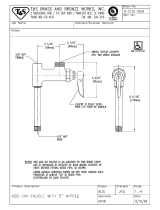
The Pre-Rinse Hot/Cold Water Faucet (H0134-01)
Item # Part # Description
1
MM-KL50-Y002-16XZ Spray Head Assembly (see Detail 1)
MM-KN50-X025-Z Grip
2 MM-KL50-Y004-44 Hose Assembly with Grip (44" LG)
3 MM-KL50-X077 Riser Pipe, 18"
4 MM-KL11-X008 Add-on Faucet 8"
5 MM-KL55-Y001-Z Faucet Body, Add-on Faucet
6 MM-KL50-Y001 Base Faucet Assembly, Double Pantry (see Detail 2)
7 MM-K50-X178 Stainless Steel Spring
8 MM-K50-Y020-Z Wall Bracket Assembly
9 MM-K50-Y011 Hook/Screw Assembly
10 MM-KL50-X032 Spring Retainer
7
8
9
10

14
Assembly of the Pre-Rinse Hot/Cold Water Faucet
The Pre-Rinse Faucet comes as a kit. General Instructions for assembly & installation are:
1. Turn off water supply at the main source.
2. Hand-tighten all parts prior to tightening with a wrench.
3. Do not force parts together.
4. All plated surfaces should be handled with care. Avoid scratching with tools.
5. Use Teflon tape when making threaded connections to water supply lines.
Below is an overview of the assembly of the Pre-Rinse Faucet.
Assemble Spray Head and Hose
• Attach the Spray Head Assembly (1) to the Hose Assembly (2 / 3)
• Attach the Spring (7) to the Hose
• Attach Spring Retainer (10) to the Hose.
Assemble the Base Faucet Body (6)
• Mount and secure the Base Faucet Body to the sink deck
After installing Base Faucet Body
• Attach the Add-on Faucet Body (5) to the Base Faucet Assembly
• Attach the Add-on Faucet (4) to the Add-on Faucet Body
Assemble Spray Head/Hose to the Faucet Bodies
• Attach the previously assembled Spray Head and Hose to the Add-on Faucet Body
Assemble Wall Bracket and Hook Assembly
• Attach the Wall Bracket Assembly (8) to the hose and affix to the wall
• Attach the Hook/screw Assembly (9) to the hose

15
Instruction Manual
Detail 1 - Spray Head Assembly (MM-KL50-Y002-16XZ) and Grip (MM-KN50-X025-Z)
The Spray Head comes pre-assembled. It is also available as a repair kit. The various parts are shown
here.
Item # Part # Description
1 MM-KL50-Y002-16XZ Pre-Rinse Spray Assembly
2 MM-KN50-Y027 Button Valve Assembly
3 MM-K50-X016-SP Spray Handle with screw assembly
4 MM-KN50-X025-Z Grip
5 MM-K50-X017 Holding Ring
6 MM-KN50-X135 Water Saver Plate (1.6 GPM)
7 MM-KL50-0200-16 Spray Head Repair Kit (includes Button Valve Assembly)
1
7
6
2
5

16
Assembly of Gooseneck Spring
1. Assemble Spring Retainer to Riser Pipe and tighten with wrench. This will also tighten the Riser Pipe
on the faucet body.
2. Assemble Hose to spring retainer. Ensure the O-ring is in place inside of the hose coupling prior to
assembly. (Additional O-rings are provided for future use.) Tighten securely.
3. Assemble Large Coil Spring over Hose and onto Spring Retainer.
IMPORTANT: Spring must be
assembled vertically with large curve of spring to the top.
4. Assemble Spring Head Ring over Spray Head Grip, and assemble Spray Head Assembly to the Hose
and tighten with wrench. Ensure that O-ring is in place prior to assembly.
Be sure that O-ring
is installed for proper
performance.
Spring Retainer
Strain Relief
Spring
Hose
Coupling
Large Coil Spring
Hose
Spray Head Ring
Spray Head Grip
Spray Head Grip
Hose
Large Coil
Spring
WRONG
DIRECTION
RIGHT
DIRECTION
Spray Head
Assembly
1
3
2
Spray Head
Assembly
Hose
Coupling
Grip
A
B

17
Instruction Manual
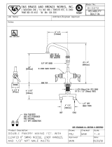
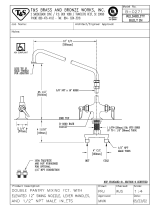
Detail 2 - Double Pantry Base Faucet Assembly (MM-KL50-Y001)
In the Pre-Rinse Faucet Assembly, the Base Faucet comes (along with handles and hot/cold valves) pre-
assembled. The Hot/Cold Valve Assemblies and the Handle Replacement can be ordered separately.
These components are also replacements for MM-KL55-Y001-Z (Add -on Faucet).
Item # Part # Description
1 MM-KN50-Y007 Hot Valve Assembly
2 MM-KN50-Y006 Cold Valve Assembly
3 MM-K50-0110 Handle Replacement Kit
3
3
1
2

18
Installation of Base Faucet Assembly (MM-KL50-Y001)
1. Remove Base Faucet body from the kit box.
2. Detach the yoke and tailpiece from the faucet body
3. Detach the washer and locknut from the Base Faucet Body
Yoke
3/8” Tail Piece
Washer
Locknut

19
Instruction Manual
Installation of Base Faucet Assembly (continued)
1. Make sure that sink top surface is free of contaminants. Then mount the Base Faucet Body in the sink
hole.
2. At the back of the sink, re-install the faucet
body washer and locknut to the male inlet.
Tighten locknut against sink deck.
3. Attach the Yoke to the Base Faucet Body.
Pre-Rinse Faucet torque and sealing
specifications:
•
For torque, hand tighten plus ½ turn
• For sealing, use Teflon tape and apply 2-3 wrap around
the threads.
Washer
Locknut
Yoke
3/8” Tailpiece

20
Install Add-on Faucet (MM-KL11-X008), Add-on Faucet Body (MM-KL55-Y001-Z)
To install the Add-on Faucet, Add-on Faucet Body (if applicable) and hose assembly (MM-KL50-Y004-44):
1. Apply Teflon tape to threads on ends of short riser pipe attached to add-on faucet. Screw the riser
pipe into faucet body and tighten.
2. Apply Teflon tape to threads on both ends of riser pipe. Screw the riser pipe into add on faucet body
and hand tighten.
Apply Teflon Tape
Apply Teflon Tape
/