Ingersoll-Rand 88H Series Maintenance Information
- Type
- Maintenance Information
Ingersoll-Rand 88H Series is an air grinder with a free speed that ranges from 9000 to 20,000 rpm. It has a 1/4-inch collet capacity and can be used for a variety of tasks, including grinding, sanding, and polishing. The 88H Series is also lightweight and easy to use, making it a great choice for both professional and DIY users.
Ingersoll-Rand 88H Series is an air grinder with a free speed that ranges from 9000 to 20,000 rpm. It has a 1/4-inch collet capacity and can be used for a variety of tasks, including grinding, sanding, and polishing. The 88H Series is also lightweight and easy to use, making it a great choice for both professional and DIY users.


-
 1
1
-
 2
2
-
 3
3
-
 4
4
-
 5
5
-
 6
6
-
 7
7
-
 8
8


Ingersoll-Rand 88H Series Maintenance Information
- Type
- Maintenance Information
Ingersoll-Rand 88H Series is an air grinder with a free speed that ranges from 9000 to 20,000 rpm. It has a 1/4-inch collet capacity and can be used for a variety of tasks, including grinding, sanding, and polishing. The 88H Series is also lightweight and easy to use, making it a great choice for both professional and DIY users.
Ask a question and I''ll find the answer in the document
Finding information in a document is now easier with AI
Related papers
-
 Casera TR-06Q User manual
-
Ingersoll-Rand 99V60P107 Operation and Maintenance Manual
-
-
Ingersoll-Rand 99V Series Maintenance Information
-
-
-
-
-
-

Other documents
-
BenQ GW2480 Operating instructions
-
Harbor Freight Tools 30304 User manual
-
Dynabrade 56723 Safety, Operation And Maintenance Manual
-
MAC TOOLS AWD099-S User manual
-
-
Simplicity 1600 Series User manual
-
-
-
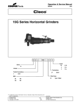 Cooper Bussmann 15G Series User manual
-
 Toku 430101V0J Operating instructions

