ESAB Fabricator Feed 304 User manual
- Category
- Welding System
- Type
- User manual
This manual is also suitable for

FabricatorFeed304,
FabricatorFeed304w
Instruction manual
0446 451 001 GB 20210426
Valid for: Serial number:
OP110YY-XXXXXX


TABLE OF CONTENTS
0446 451 001
- 3 -
© ESAB AB 2021
1 SAFETY
......................................................................................................................................
4
1.1 Meaning of symbols
....................................................................................................
4
1.2 Safety precautions
......................................................................................................
4
2 INTRODUCTION
.........................................................................................................................
7
2.1 Overview
......................................................................................................................
7
2.2 Equipment
....................................................................................................................
7
3 TECHNICAL DATA
.....................................................................................................................
8
4 INSTALLATION
...........................................................................................................................
10
4.1 Overview
.....................................................................................................................
10
4.2 Lifting Instructions
......................................................................................................
10
5 OPERATION
...............................................................................................................................
11
5.1 Overview
......................................................................................................................
11
5.2 Connection and control devices
................................................................................
13
5.3 Water connection
.......................................................................................................
13
5.4 Starting procedure
......................................................................................................
13
5.5 Function explanations
................................................................................................
13
5.6 Wire feed pressure
......................................................................................................
14
5.7 Changing and loading wire
.........................................................................................
14
5.8 Changing feed rollers
..................................................................................................
14
6 MAINTENANCE
..........................................................................................................................
16
6.1 Overview
......................................................................................................................
16
6.2 Inspection and cleaning
..............................................................................................
16
7 ORDERING SPARE PARTS
.......................................................................................................
17
WIRING DIAGRAM
................................................................................................................................
18
ORDERING NUMBERS
.........................................................................................................................
19
ACCESSORIES
.....................................................................................................................................
20
WEAR PARTS
........................................................................................................................................
23

1 SAFETY
0446 451 001
- 4 -
© ESAB AB 2021
1 SAFETY
1.1 Meaning of symbols
As used throughout this manual: Means Attention! Be Alert!
DANGER!
Means immediate hazards which, if not avoided, will result in immediate, serious
personal injury or loss of life.
WARNING!
Means potential hazards which could result in personal injury or loss of life.
CAUTION!
Means hazards which could result in minor personal injury.
WARNING!
Before use, read and understand the instruction manual and
follow all labels, employer´s safety practices and Safety Data
Sheets (SDSs).
1.2 Safety precautions
Users of ESAB equipment have the ultimate responsibility for ensuring that anyone who works on or
near the equipment observes all the relevant safety precautions. Safety precautions must meet the
requirements that apply to this type of equipment. The following recommendations should be observed
in addition to the standard regulations that apply to the workplace.
All work must be carried out by trained personnel well-acquainted with the operation of the equipment.
Incorrect operation of the equipment may lead to hazardous situations which can result in injury to the
operator and damage to the equipment.
1. Anyone who uses the equipment must be familiar with:
• its operation
• location of emergency stops
• its function
• relevant safety precautions
• welding and cutting or other applicable operation of the equipment
2. The operator must ensure that:
• no unauthorised person is stationed within the working area of the
equipment when it is started up
• no-one is unprotected when the arc is struck or work is started with the
equipment
3. The workplace must:
• be suitable for the purpose
• be free from drafts
4. Personal safety equipment:
• Always wear recommended personal safety equipment, such as safety
glasses, flame-proof clothing, safety gloves
• Do not wear loose-fitting items, such as scarves, bracelets, rings, etc.,
which could become trapped or cause burns
5. General precautions:
• Make sure the return cable is connected securely
• Work on high voltage equipment may only be carried out by a
qualified electrician

1 SAFETY
0446 451 001
- 5 -
© ESAB AB 2021
• Appropriate fire extinguishing equipment must be clearly marked and
close at hand
• Lubrication and maintenance must not be carried out on the equipment
during operation
WARNING!
Wire feeders are intended to be used with power sources in MIG/MAG mode only.
If used in any other welding mode, such as MMA, the welding cable between wire feeder
and power source must be disconnected, or else the wire feeder becomes live or
energized.
If equipped with ESAB cooler
Use ESAB approved coolant only. Non-approved coolant might damage the equipment and jeopardize
product safety. In case of such damage, all warranty undertakings from ESAB cease to apply.
Recommended ESAB coolant ordering number: 0465720002.
For ordering information, see the "ACCESSORIES" chapter in the instruction manual.
WARNING!
Arc welding and cutting can be injurious to yourself and others. Take precautions when
welding and cutting.
ELECTRIC SHOCK - Can kill
• Do not touch live electrical parts or electrodes with bare skin, wet gloves
or wet clothing
• Insulate yourself from work and ground.
• Ensure your working position is safe
ELECTRIC AND MAGNETIC FIELDS - Can be dangerous to health
• Welders having pacemakers should consult their physician before welding.
EMF may interfere with some pacemakers.
• Exposure to EMF may have other health effects which are unknown.
• Welders should use the following procedures to minimize exposure to
EMF:
○ Route the electrode and work cables together on the same side
of your body. Secure them with tape when possible. Do not
place your body between the torch and work cables. Never coil
the torch or work cable around your body. Keep welding power
source and cables as far away from your body as possible.
○ Connect the work cable to the workpiece as close as possible
to the area being welded.
FUMES AND GASES - Can be dangerous to health
• Keep your head out of the fumes
• Use ventilation, extraction at the arc, or both, to take fumes and gases
away from your breathing zone and the general area
ARC RAYS - Can injure eyes and burn skin
• Protect your eyes and body. Use the correct welding screen and filter lens
and wear protective clothing
• Protect bystanders with suitable screens or curtains
NOISE - Excessive noise can damage hearing
Protect your ears. Use earmuffs or other hearing protection.

1 SAFETY
0446 451 001
- 6 -
© ESAB AB 2021
MOVING PARTS - Can cause injuries
• Keep all doors, panels and covers closed and securely in place. Have only
qualified people remove covers for maintenance and troubleshooting as
necessary. Reinstall panels or covers and close doors when service is
finished and before starting engine.
• Stop engine before installing or connecting unit.
• Keep hands, hair, loose clothing and tools away from moving parts.
FIRE HAZARD
• Sparks (spatter) can cause fire. Make sure therefore that there are no
inflammable materials nearby
• Do not use on closed containers.
HOT SURFACE - Parts can burn
• Do not touch parts bare handed.
• Allow cooling period before working on equipment.
• To handle hot parts, use proper tools and/or insulated welding gloves to
prevent burns.
MALFUNCTION - Call for expert assistance in the event of malfunction.
PROTECT YOURSELF AND OTHERS!
CAUTION!
This product is solely intended for arc welding.
CAUTION!
Class A equipment is not intended for use in residential
locations where the electrical power is provided by the public
low-voltage supply system. There may be potential difficulties in
ensuring electromagnetic compatibility of class A equipment in
those locations, due to conducted as well as radiated
disturbances.
NOTE!
Dispose of electronic equipment at the recycling facility!
In observance of European Directive 2012/19/EC on Waste
Electrical and Electronic Equipment and its implementation in
accordance with national law, electrical and/or electronic
equipment that has reached the end of its life must be disposed
of at a recycling facility.
As the person responsible for the equipment, it is your
responsibility to obtain information on approved collection
stations.
For further information contact the nearest ESAB dealer.
ESAB has an assortment of welding accessories and personal protection equipment for
purchase. For ordering information contact your local ESAB dealer or visit us on our website.

2 INTRODUCTION
0446 451 001
- 7 -
© ESAB AB 2021
2 INTRODUCTION
2.1 Overview
The FabricatorFeed304, FabricatorFeed304w wire feed unit is intended for MIG/MAG-welding
together with welding power sources:
• Fabricator EM 401i
• FabricatorEM 401i with cooling unit
• FabricatorEM 501i with cooling unit
They come in different variants, see chapter "Ordering Numbers".
The wire feed units are sealed and contain four-wheel drive wire feed mechanisms as well as control
electronics.
They can be used together with wire from ESAB's MarathonPac, or from wire bobbin (standard Ø 200
mm, Ø 300 mm and accessory Ø 440 mm).
The wire feed unit can be placed on a trolley, suspended above the workplace with a lifting eye, on a
counter balance or on the floor with or without wheel set.
ESAB accessories for the product can be found in the "ACCESSORIES" chapter of this manual.
2.2 Equipment
The FabricatorFeed304, FabricatorFeed304w wire feed unit is supplied with:
• Instruction manual
• Four Ø1.0/1.2mm V-groove (assembled)
• Sticker with recommended wear parts

3 TECHNICAL DATA
0446 451 001
- 8 -
© ESAB AB 2021
3 TECHNICAL DATA
FabricatorFeed304, FabricatorFeed304w
Power Supply voltage 42 V DC
Power requirement 252 VA
Rated supply current I
1
6 A
Settings data
Wire feed speed
1.5–25.0 m/min (4.9–82 ft/min)
Torch connection EURO
Max. diameter wire bobbin 300 mm (*440 mm), 12 inch (*17 inch)
Wire dimension
Fe 0.8–1.6 mm (0.030 – 1/16 inch)
SS 0.8–1.6 mm (0.030 – 1/16 inch)
Cored wire 0.9–1.6 mm (0.035 – 1/16 inch)
Weight
FabricatorFeed304 with bobbin cover 13.9kg (30.6Ibs)
FabricatorFeed304w with bobbin cover 14.2kg (31.3Ibs)
Wire spool weight (ESAB standard)
Ø 200 mm 5 kg (11.0 lbs)
Ø 300 mm 18 kg (39.7 lbs)
Ø 440 mm 30 kg (66.1 lbs)
Dimensions (l × w × h)
(basic)
675×265×418mm (26.6×10.4×16.5inch)
Operating temperature -10° to +40°C (+14° to +104°F)
Transport and storage temperature -20° to +55°C (-4° to +131°F)
Shielding gas
max pressure
All types intended for MIG/MAG welding
5 bar (0.5 Mpa)
Coolant(FabricatorFeed304w)
max pressure
ESAB's ready mixed coolant
5 bar (0.5 Mpa)
Permissible load at
60% duty cycle 500 A
100% duty cycle 400 A
Enclosure class IP23
with the Ø 440 mm (Ø 17 inch) bobbin and/or the
counter balance device
IP2X
*)
See the "ACCESSORIES" chapter in the instruction manual.
Duty cycle
The duty cycle refers to the time as a percentage of a ten-minute period that you can weld or cut at a
certain load without overloading. The duty cycle is valid for 104°F (40°C).
Enclosure class
The IP code indicates the enclosure class, i.e. the degree of protection against penetration by solid
objects or water.

3 TECHNICAL DATA
0446 451 001
- 9 -
© ESAB AB 2021
Equipment marked IP23 is intended for indoor and outdoor use.
Equipment marked IP2X is intended for indoor use.

4 INSTALLATION
0446 451 001
- 10 -
© ESAB AB 2021
4 INSTALLATION
4.1 Overview
The installation must be carried out by a professional.
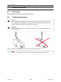
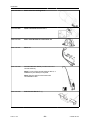
4.2 Lifting Instructions
CAUTION!
Risk of crushing when lifting the wire feeder. Mounting a large wire bobbin (Ø 440 mm),
may change the centre of gravity of the wire feeder and increase the risk of tipping and
crushing. Protect yourself and warn bystanders of the risk.
CAUTION!
To avoid personal injury and / or equipment damage, lift using method and attachment
points shown here.
Ordering number for the lifting eye can be found in chapter "Order Number".
NOTE!
If another mounting device is used, this should be insulated from the wire feed unit.

5 OPERATION
0446 451 001
- 11 -
© ESAB AB 2021
5 OPERATION
5.1 Overview
General safety regulations for handling the equipment can be found in the "SAFETY" chapter
of this manual. Read it through before you start using the equipment!
WARNING!
To avoid shock, do not touch electrode wire or parts in contact with it, or uninsulated cable
or connections.
NOTE!
When moving the equipment, use handle intended for transportation. Never pull the
equipment by the welding torch.
WARNING!
Assure that the side panels are closed during operation.
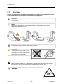
WARNING!
To prevent the reel from sliding off the
hub: Lock the reel in place by turning
the red knob as shown on the warning
label attached next to the hub.
CAUTION!
Before threading welding wire, make sure the chisel point and burrs have been removed
from the end of the wire to prevent the wire from jamming in the torch liner.
WARNING!
Rotating parts can cause injury, take great care.

5 OPERATION
0446 451 001
- 12 -
© ESAB AB 2021
WARNING!
There is a risk of tipping if the wire feed unit is fitted with a counterbalance arm. Make sure
to install the stabilizer kit and secure the equipment, especially if used on an uneven or
sloping surface.
Recommended maximum welding current values for the interconnection set at an ambient
temperature of +25°C and normal 10minutes cycle
Cable size (mm
2
)
Duty cycle
Voltage drop /
10m
100% 60% 35%
50 285A 320A 370A 0.352V / 100A
70 355A 400A 480A 0.254V / 100A
95 430A 500A 600A 0.189V / 100A
Recommended maximum welding current values for the interconnection set at an ambient
temperature of +40°C and normal 10minutes cycle
Cable size (mm
2
)
Duty cycle
Voltage drop /
10m
100% 60% 35%
50 250A 280A 320A 0.372V / 100A
70 310A 350A 420A 0.268V / 100A
95 375A 440A 530A 0.2V / 100A
Duty cycle
The duty cycle refers to the time as a percentage of a ten-minute period that you can weld or cut at a
certain load without overloading. The duty cycle is valid for 40°C/104°F, or below.

5 OPERATION
0446 451 001
- 13 -
© ESAB AB 2021
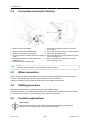
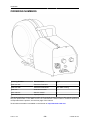
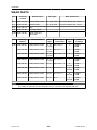
5.2 Connection and control devices
1 Knob for setting the voltage 7 Connection for welding current from power
source (OKC)
2 Knob for setting the wirefeed speed 8 Connection for control cable from power source
3 Switch for wire inching or gas purge 9 Connection for shielding gas
4 Connection RED for cooling water from welding
torch *)
10 Connection BLUE for cooling water from power
source (cooling unit) *)
5 Connection BLUE for cooling water to the
welding torch *)
11 Connection RED for cooling water to power
source (cooling unit) *)
6 Connection for the welding torch
NOTE!
*) Cooling water connections only available on certain models.
5.3 Water connection
When connecting a water-cooled welding torch, the main power supply switch of the power source
must be in the OFF position and the cooling unit switch must be in position 0.
A water connection kit can be orderred as accessory, see chapter "Accessories".
5.4 Starting procedure
When the wire feed starts, the power source generates welding voltage.
If there is no welding current flow within ten seconds, the power source switches the welding voltage
off. The wire feed continues until the welding torch's switch is switched off.
5.5 Function explanations
Wire inching
Wire inching is used when one needs to feed wire without welding voltage being
applied. The wire is fed as long as the button is depressed.

5 OPERATION
0446 451 001
- 14 -
© ESAB AB 2021
Wire feed speed
This sets the required feed speed of the filler wire in m/minute.
The corresponding current for the respective wire feed speed will be displayed on the
power source.
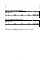
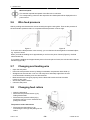
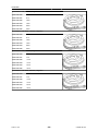
5.6 Wire feed pressure
Start by making sure that the wire moves smoothly through the wire guide. Then set the pressure of
the wire feeder's pressure rollers. It is important that the pressure is not too high.
Figure A Figure B
To check that the feed pressure is set correctly, you can feed out the wire against an insulated object,
e.g. a piece of wood.
When you hold the welding torch approximately 5mm from the piece of wood (Figure A), the feed
rollers should slip.
If you hold the welding torch approximately 50 mm from the piece of wood, the wire should be fed out
and bend (Figure B).
5.7 Changing and loading wire
• Open the side panel.
• Disconnect the pressure sensor by folding it backwards, the pressure rollers slide up.
• Straighten out the new wire 10-20 cm. File away burrs and sharp edges from the end
of the wire before inserting it into the wire feed unit.
• Make sure that the wire goes properly into the feed roller's track and into the outlet
nozzle or wire guide.
• Secure the pressure sensor.
• Close the side panel.
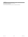
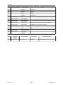
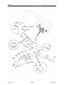
5.8 Changing feed rollers
• Open the side panel.
• Disconnect the pressure sensor (1) by
folding it backwards.
• Disconnect the pressure rollers (2) by
turning the axle (3) 1/4 turn clockwise and
pulling out the axle.
The pressure rollers disconnect
• Disconnect the feed rollers (4) by
unscrewing the nuts (5) and pulling out the
rollers.

5 OPERATION
0446 451 001
- 15 -
© ESAB AB 2021
During installation, repeat the above in the reverse order.
Choice of track in the feed rollers
Turn the feed roller with the dimensioning mark for the required track towards you.

6 MAINTENANCE
0446 451 001
- 16 -
© ESAB AB 2021
6 MAINTENANCE
6.1 Overview
NOTE!
Regular maintenance is important for safe and reliable operation.
CAUTION!
All warranty undertakings from the supplier cease to apply if the customer attempts any
work to rectify any faults in the product during the warranty period.
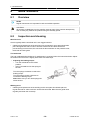
6.2 Inspection and cleaning
Wire feed unit
Check regularly that the wire feed unit is not clogged with dirt.
• Cleaning and replacement of the wire feed unit mechanism's worn parts should take
place at regular intervals in order to achieve trouble-free wire feed. Note that if
pre-tensioning is set too hard, this can result in abnormal wear on the pressure roller,
feed roller and wire guide.
The brake hub
The hub is adjusted when delivered, if readjustment is required, follow the instructions below. Adjust
the brake hub so that wire is slightly slack when wire feed stops.
• Adjusting the braking torque:
○ Turn the red handle to the locked
position.
○ Insert a screwdriver into the springs in
the hub.
Turn the springs clockwise to reduce the
braking torque.
Turn the springs counter-clockwise to
increase the braking torque.
Note: Make sure you turn both springs the
same amount.
Welding torch
• Cleaning and replacement of the welding torch's wear parts should take place at
regular intervals in order to achieve trouble-free wire feed. Blow the wire guide clean
regularly and clean the contact tip.

7 ORDERING SPARE PARTS
0446 451 001
- 17 -
© ESAB AB 2021
7 ORDERING SPARE PARTS
CAUTION!
Repair and electrical work should be performed by an authorised ESAB service technician.
Use only ESAB original spare and wear parts.
The FabricatorFeed304 and FabricatorFeed304w are designed and tested in accordance with
international and European standards IEC/EN 60974-5 and IEC/EN 60974-10. On completion of
service or repair work, it is the responsibility of the person(s) performing the work to ensure that the
product still complies with the requirements of the above standards.
Spare parts and wear parts can be ordered through your nearest ESAB dealer, see esab.com. When
ordering, please state product type, serial number, designation and spare part number in accordance
with the spare parts list. This facilitates dispatch and ensures correct delivery.

APPENDIX
0446 451 001
- 18 -
© ESAB AB 2021
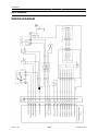
APPENDIX
WIRING DIAGRAM

APPENDIX
0446 451 001
- 19 -
© ESAB AB 2021
ORDERING NUMBERS
Ordering Number Denomination Type
0446 401 881 FabricatorFeed304
0446 401 882 FabricatorFeed304w with water cooling
0446 451 * Instruction manual
0463 788 001 Service manual
0463 795 001 Spare parts list
The three last digits in the document number of the manual show the version of the manual. Therefore
they are replaced with * here. Make sure to use a manual with a serial number or software version that
corresponds with the product, see the front page of the manual.
Technical documentation is available on the Internet at: http://manuals.esab.com.

APPENDIX
0446 451 001
- 20 -
© ESAB AB 2021
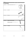
ACCESSORIES
0458 674 880 Bobbin cover kit, plastic Ø 300 mm
0458 707 880 Wheel kit
0458 707 881 Wheel kit
0459 233 880 Adapter for Ø 440 mm bobbin
Note! IP23 not valid for wire feeder with Ø 17,32
Inch (400 mm) bobbin.
0458 706 880 Lifting eye
Page is loading ...
Page is loading ...
Page is loading ...
Page is loading ...
Page is loading ...
Page is loading ...
Page is loading ...
Page is loading ...
-
 1
1
-
 2
2
-
 3
3
-
 4
4
-
 5
5
-
 6
6
-
 7
7
-
 8
8
-
 9
9
-
 10
10
-
 11
11
-
 12
12
-
 13
13
-
 14
14
-
 15
15
-
 16
16
-
 17
17
-
 18
18
-
 19
19
-
 20
20
-
 21
21
-
 22
22
-
 23
23
-
 24
24
-
 25
25
-
 26
26
-
 27
27
-
 28
28


ESAB Fabricator Feed 304 User manual
- Category
- Welding System
- Type
- User manual
- This manual is also suitable for
Ask a question and I''ll find the answer in the document
Finding information in a document is now easier with AI
Related papers
-
ESAB COOL 2 Standalone User manual
-
ESAB EM 501i User manual
-
ESAB Robust Feed Pro: Connect L User manual
-
ESAB Fabricator Feed 364 User manual
-
-
ESAB COOL 2 User manual
-
-
ESAB Robust Feed PRO User manual
-
ESAB Warrior™ Feed 304 User manual
-