Page is loading ...

Relion
®
605 series
Relion
®
605 series
Feeder protection and control /
Feeder protection
REF601 / REJ601
Application manual
Relion
®
605 series


Document ID: 1MDU07212-YN
Issued: 2012-09-28
Revision: revision: A
Product version: 2.1
© Copyright 2012 ABB. All rights reserved

Copyright
This document and parts thereof must not be reproduced or copied without written
permission from ABB, and the contents thereof must not be imparted to a third
party, nor used for any unauthorized purpose.
The software or hardware described in this document is furnished under a license
and may be used, copied, or disclosed only in accordance with the terms of such
license.
Trademarks
ABB and Relion are registered trademarks of ABB Group. All other brand or
product names mentioned in this document may be trademarks or registered
trademarks of their respective holders.
Warranty
Please inquire about the terms of warranty from your nearest ABB representative.
ABB Limited,
Distribution Automation
Maneja,
Vadodara, India
Telephone: +91 265 2604386
Fax: +91 265 2638922
http://www.abb.com/substationautomation

Disclaimer
The data, examples and diagrams in this manual are included solely for the concept
or product description and are not to be deemed as a statement of guaranteed
properties. All persons responsible for applying the equipment addressed in this
manual must satisfy themselves that each intended application is suitable and
acceptable, including that any applicable safety or other operational requirements
are complied with. In particular, any risks in applications where a system failure
and/or product failure would create a risk for harm to property or persons
(including but not limited to personal injuries or death) shall be the sole
responsibility of the person or entity applying the equipment, and those so
responsible are hereby requested to ensure that all measures are taken to exclude or
mitigate such risks.
This document has been carefully checked by ABB but deviations cannot be
completely ruled out. In case any errors are detected, the reader is kindly requested
to notify the manufacturer. Other than under explicit contractual commitments, in
no event shall ABB be responsible or liable for any loss or damage resulting from
the use of this manual or the application of the equipment.

Conformity
This product complies with the directive of the Council of the European
Communities on the approximation of the laws of the Member States relating to
electromagnetic compatibility (EMC Directive 2004/108/EC) and concerning
electrical equipment for use within specified voltage limits (Low-voltage directive
2006/95/EC). This conformity is the result of tests conducted by ABB in
accordance with the product standards EN 50263 and EN 60255-26 for the EMC
directive, and with the product standards EN 60255-1 and EN 60255-27 for the low
voltage directive. The IED is designed in accordance with the international
standards of the IEC 60255 series.

Table of contents
REF601 / REJ601 1
Application Manual
Table of contents
Section 1 General .................................................................. 5
1.1 This manual ................................................................................................ 5
1.2 Intended audience ...................................................................................... 5
1.3 Document revision history ........................................................................... 5
1.4 Document symbol and conventions ............................................................. 6
Section 2 REF601/REJ601 overview ..................................... 7
2.1 Overview .................................................................................................... 7
2.2 Product version history ............................................................................... 7
2.3 Operation functionality ................................................................................ 8
2.3.1 Relay functions ...................................................................................... 8
2.3.2 Optional function .................................................................................... 8
2.4 Other functions ........................................................................................... 9
2.4.1 Self-supervision ..................................................................................... 9
2.4.2 Fault record and trip counter ................................................................ 10
2.4.3 Event log ............................................................................................. 10
2.4.4 Real time clock .................................................................................... 11
2.4.5 Access control ..................................................................................... 12
2.4.6 Power-ON sequence............................................................................ 12
Section 3 Technical data ..................................................... 13
Section 4 Protection and control function ............................. 13
4.1 Three Phase overcurrent protection .......................................................... 13
4.1.1 Functionality ........................................................................................ 13
4.1.2 Principle of operation ........................................................................... 13
4.1.3 Setting range of three phase overcurrent protection ............................. 13

Table of contents
2 REF601 / REJ601
Application Manual
4.2 Earth fault protection ..................................................................................14
4.2.1 Functionality .........................................................................................14
4.2.2 Principle of operation ............................................................................14
4.2.3 Setting range of earth fault overcurrent protection .................................15
4.3 Three phase inrush detector ......................................................................15
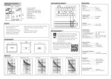
4.4 Protection characteristics ...........................................................................16
4.4.1 Time / current characteristics ................................................................16
4.4.2 IEC characteristic..................................................................................16
4.4.3 RI type characteristic ............................................................................17
4.5 Configurable binary outputs .......................................................................17
4.6 Configurable binary inputs .........................................................................18
4.7 Breaker control and trip command operation ..............................................19
4.8 Trip circuit supervision ...............................................................................19
4.9 Signal diagram ..........................................................................................21
Section 5 Use of LHMI ......................................................... 23
5.1 Overview ...................................................................................................23
5.1.1 LED’s ...................................................................................................23
5.1.2 LCD display ..........................................................................................24
5.1.3 Navigation ............................................................................................24
5.1.4 Authorization ........................................................................................25
5.1.5 Configuration status ..............................................................................26
5.2 LHMI menu navigation ...............................................................................26
5.2.1 Default screen ......................................................................................26
5.2.2 Main menu............................................................................................27
5.2.3 Menu – Measurement ...........................................................................28
5.2.4 Menu – Recorded data ..........................................................................29
5.2.5 Menu - Events ......................................................................................29
5.2.6 Menu – Setting......................................................................................30
5.2.7 Menu – Configuration ............................................................................32

Table of contents
REF601 / REJ601 3
Application Manual
5.2.8 Menu – Test ......................................................................................... 36
5.2.9 Access level ........................................................................................ 40
5.2.10 Version information .............................................................................. 41
Section 6 Installation ........................................................... 42
6.1 Unpacking and inspecting the device ........................................................ 42
6.2 Storage..................................................................................................... 42
6.3 Checking environmental condition and mounting space ............................ 42
6.4 Relay wiring .............................................................................................. 43
6.5 Relay mounting and dimensions ............................................................... 43
6.6 Relay ordering information ........................................................................ 46
6.7 Accessories and ordering data .................................................................. 46
6.8 Setting table ........................................................................................... 46


1MDU07212-YN Rev. A Section 1
General
REF601 / REJ601 5
Application Manual
Section 1 General
1.1 This manual
This manual contains application and functionality descriptions and connection
diagrams, input and output signals, setting parameters and technical data. The
manual can be used as a technical reference during the engineering phase,
installation and commissioning phase, and during normal service. The manual can
also be used when calculating settings. The manual provides instructions on how to
operate the IED during normal service once it has been commissioned and to find
out how to handle disturbances or view calculated and measured network data in
order to determine the cause of a fault.
1.2 Intended audience
This manual addresses system engineers, installation and commissioning
personnel, who use technical data during engineering, installation and
commissioning, and in normal service. system engineer must have a thorough
knowledge of protection systems, protection equipment, protection functions and
the configured functional logics in the IEDs. The installation and commissioning
personnel must have a basic knowledge in handling electronic equipment.
This manual addresses Protection and control engineer responsible for planning,
pre-engineering and engineering. The protection and control engineer must be
experienced in electrical power engineering and have knowledge of related
technology, such as communication and protocols.
The manual also addresses the operator, who operates the IED on a daily basis. The
operator must be trained in and have a basic knowledge of how to operate
protection equipment. The manual contains terms and expressions commonly used
to describe this kind of equipment.
1.3 Document revision history
Document
revision/date
Product version Document history
A / 28.09.2012 2.1
Release of REF601
/REJ601
with
conventional current transformer

Section 1 1MDU07212-YN Rev. A
General
6 REF601 / REJ601
Application Manual
1.4 Document symbol and conventions
This publication includes the following icons that point out safety-related
conditions or other important information:
Safety indication symbols
The information icon alerts the reader to important facts and
conditions.
Non-observance can result in death, personal injury or substantial
property damage
Breaking the sealing tape on the upper handle of the device will
result in loss of warranty and proper operation will no longer be
guaranteed.
When the plug-in unit has been detached from the case, do not
touch the inside of the case. The relay case internals may contain
high voltage potential and touching these may cause personal
injury.
The warning icon indicates the presence of a hazard which could
result in personal injury.
Dangerous voltages can occur on the connectors, even though the
auxiliary voltage has been disconnected.
National and local electrical safety regulations must always be
followed.
The device contains components which are sensitive to Electrostatic
discharge. Unnecessary touching of electronic components must
therefore be avoided.
Only a competent electrician is allowed to carry out the electrical
installation.
The caution icon indicates important information or warning related
to the concept discussed in the text. It might indicate the presence of
a hazard which could result in corruption of software or damage to
equipment or property.
The tip icon indicates advice on, for example, how to design your
project or how to use a certain function.

1MDU07212-YN Rev. A Section 2
REF601/REJ601 overview
REF601 / REJ601 7
Application Manual
Section 2 REF601/REJ601 overview
2.1 Overview
REF601/REJ601 is a dedicated feeder protection relay, intended for the protection
of utility substations and industrial power systems, in primary and secondary
distribution networks. REF601/REJ601 is a member of ABB’s Relion ® product
family and part of its 605 series.
The relay provides an optimized composition of protection, monitoring and control
functionality in one unit, with the best performance usability in its class and is
based on ABB’s in-depth knowledge of protection and numerical technology.
The REF601/REJ601 features compact size and ease of use. The features include:
Standard 1A or 5A CT input for phase current measurement
Earth current measurement internally or externally through CBCT
Three-stage overcurrent protection
Two-stage earth-fault protection
Inrush detection for stability during transformer charging
Local and remote control of circuit breaker
Trip Circuit Supervision and relay internal supervision
Lockout function
100 event logs with date and time stamping
Five analogue fault records
Non-resettable trip counter
On-line current measurements in primary value
Comprehensive local HMI
Universal auxiliary supply
Optional MODBUS RTU communication
Non-volatile memory for setting and fault records
User selectable rated frequency 50 / 60 Hz
Configurable binary inputs and outputs
2.2 Product version history
Product version Release date Product History
1.0 20.03.2009 Product released
1.0 SP1 21.08.2009 Service Pack released
2.0 04.04.2012 Version 2.0 released
2.1
28
.0
9
.2012
Version 2.1 release with support
of conventional current
transformer

Section 2 1MDU07212-YN Rev. A
REF601/REJ601 overview
8 REF601 / REJ601
Application Manual
2.3 Operation Functionality
2.3.1 Relay functions
REF601/REJ601 offers pre-configured functionality which facilitates easy and fast
commissioning of switchgear. To emphasize the simplicity of relay’s usage, only
application specific parameters needs to set within the relay’s intended area of
application.
The settings can be changed via LHMI (Local Human-Machine Interface) or
through optional communication interface MODBUS master with setting
capability.
The relay offers protection, control, measurement and condition monitoring
functionality.
The table indicates the Functions supported by the IED
Table 1: Relay functions
Function IEC 60617 ANSI
Protection
Non Directional Over-current, Low set 3I> 51
Non Directional Over-current, High set 3I>> 50-1
Non Directional Over-current, Instantaneous set 3I>>> 50-2
Non Directional Earth-fault, Low-set I0> 51N
Non Directional Earth-fault, High-set I0>> 50N
3-phase Transformer Inrush detector 3I2f> 68
Control
1)
Circuit-breaker control I <-> O CB I <-> O CB
Condition monitoring
Trip circuit supervision TCS TCM
Measurement
Three-phase current measurement 3I 3I
Residual current measurement Io In
1) Control functionality shall not be available in REJ601 relay
2.3.2 Optional function
Communication on MODBUS RTU Protocol

1MDU07212-YN Rev. A Section 2
REF601/REJ601 overview
REF601 / REJ601 9
Application Manual
2.4 Other Functions
2.4.1 Self-Supervision
The IED is provided with an extensive self-supervision system which continuously
supervises the software and the electronics. It handles run-time fault situations and
informs the user about a fault via the LHMI.
At normal condition (no internal fault), the green Ready LED glow and the self-
supervision output contact is closed.
When an internal fault is detected in the IED, the green LED ceases to glow and
the self-supervision contact closes. Also, all other outputs are released.
Figure 1: Behavior of contact assigned for Unit ready / IRF
Internal fault indications have the highest priority on the LHMI. None of other
LHMI indications can override the internal fault indication. An indication about the
fault is shown as a message on the LHMI.
The internal fault code indicates the type of internal IED fault
Table 2: Internal fault indications and fault codes
Internal fault code Type of fault
IRF 008 Internal supply voltage check
IRF 016 Power on “EEPROM“ check fault
IRF 032 Runtime “EEPROM“ check fault
IRF 064 Gain check fault
The user can try to eliminate the fault by restarting the IED. If the fault is found to
be permanent, the IED stays in internal fault mode.
5
6
BO4
(IRF)
XK2:
5
6
BO4
(IRF)
XK2:
Normal
condition
or no auxiliary power
IRF
condition

Section 2 1MDU07212-YN Rev. A
REF601/REJ601 overview
10 REF601 / REJ601
Application Manual
2.4.2 Fault record and Trip counter
The relay stores records of analog values for last five trip events in non-volatile
memory. The fault recording is triggered by the trip signal of a protection function.
Each fault record includes the rms current values of fundamental component for all
three phases and the neutral current at five different times along the trip event.
Figure 2: Fault record
These records enable the user to analyze the five most recent power system events.
The oldest recording is lost when a new fault recording is made.
Additional, the relay count the number of phase fault trip and earth fault trip into
dedicated trip counters. These trip counters cannot be reset by the user and are
stored in nonvolatile memory.
The values of fault records and trip counters are accessible locally LHMI and
remotely via communication interface of the relay.
2.4.3 Event Log
To collect sequence-of-events (SoE) information, the relay incorporates a non-
volatile memory to store 100 event logs. Each event log includes type of event
along with date and time stamping. The event logs are stored sequentially, the most
recent being first and so on.
The SoE information are accessible locally via LHMI and remotely via
communication interface of the relay.

1MDU07212-YN Rev. A Section 2
REF601/REJ601 overview
REF601 / REJ601 11
Application Manual
Table 3: List of event types and related description
Sr.
No.
Event type Description
Data
considered
1
Power supply
presence
Unit ready contact activation will be stored
as an event. This unit ready contact is
activated when power supply is on and no
internal relay fault detected
Unit Ready
2
Trip circuit
supervision
When trip circuit becomes faulty, an event
of trip circuit faulty will be recorded.
TCS fault
3
Setting
parameter
change
Settings (I>,I>>,I>>>,Io>,Io>>
and
t>,t>>,t>>>,to>,to>>) alteration will be
captured as an event without setting value.
Any from
–
I>, I>>, I>>>,
Io>, Io>>, t>,
t>>,t>>>, to>,
to>>
4
Protection start
Start event by I>,I>> OR I>>> will be
captured as single event i.e. Phase start
Start event by Io> OR Io>> will be stored as
single event i.e. Earth start.
Start of
Phase
Start of Earth
5
Protection trip
In the event of Tripping, which protection
stage (I>, I>>, I>>>, Io> and Io>>) caused
trip will be captured as an event
information.
Any from
–
I>, I>>, I>>>,
Io>, Io>>
6
IRF
“IRF”
–
internal relay fault shall be captured
as an event.
IRF codes
7
Breaker open
When breaker open
operated
Breaker Open
8
Breaker close
When breaker close
operated
Breaker Close
9
Remote trip
When remotely trip command issued
Remote Trip
10
Reset
When reset of
protection trip,
LEDs
and
screen done
Reset
11
Blocking
When blocking by binary input
BI Blocking
12
Breaker
position
When breaker open,
close or
maintenance
position sensed by associated binary input
CB POS CLS
CB POS OPN
CB Maint
13
Memory read
fail
In case unable to read Event from eeprom
,
a message i.e.”Memory Read Fail” will be
displayed for that particular event
Memory Read
Fail
2.4.4 Real Time Clock
IED comes with a real time clock with user settable date and time. Date can be set
in “DD/MM/YY” format and time can be set in “HH:MM:SEC” format. The time
stamping have 1 ms resolution. RTC is used for time stamping the event logs and
as well as fault records . In case of power failure RTC will have a stored energy
backup for around 48 hrs. at ambient temperature when stored energy element is
fully charged. Initial time setting is “01/01/2011” and “00:00:00:000”.

Section 2 1MDU07212-YN Rev. A
REF601/REJ601 overview
12 REF601 / REJ601
Application Manual
2.4.5 Access Control
To protect the relay from unauthorized access and to maintain the integrity of
information, the relay is armed with a three level, role-based user authentication
system with individual password for the operator, engineer (Setting level) and
administrator level. The password is a combination of different navigation keys.
2.4.6 Power-ON sequence
The Power-ON sequence takes around 6 sec.
In case the optional communication on MODBUS is present, the startup time takes
around 40 sec.

1MDU07212-YN Rev. A Section 3
Technical Data
REF601 / REJ601 13
Application Manual
Section 3 Technical Data
For detailed technical data please refer the product guide.
Section 4 Protection and Control Function
4.1 Three Phase Overcurrent Protection
4.1.1 Functionality
The three-phase overcurrent protections can be used as three phase non-directional
overcurrent and short-circuit protection for feeders.
The operate time characteristics for low stage can be selected to be either definite
time (DT) or inverse definite minimum time (IDMT). The high and instantaneous
stage always operates with the definite time (DT) characteristics.
4.1.2 Principle of Operation
The three-phase overcurrent unit continuously measures all three phase currents of
the protected object. The maximum current of the three phases is evaluated by the
low stage (I> / 51), high stage (I>> / 50/51) and instantaneous stage (I>>> / 50) of
phase overcurrent functions.
On occurrence of fault, fulfilling the trip condition of respective stage, the LED
“Trip” and “Trip Ip” will be activated. Additional the output relays (Trip and
signalization) will be activated according the binary output configuration.
Each of the stages could be blocked by settings or via binary input of the relay.
4.1.3 Setting range of Three Phase Overcurrent Protection
Table 4: Setting ranges Non-directional overcurrent protection, Low stage 3I>, 51
Description Value
Measurement range 0.2...25 x In
Setting range of pick-up current I > 0.2...2.50 x In in steps 0.001, infinite
Operate time delay (DT) t > 0.04...64 sec in steps of 0.01
Operating curve type (IDMT)
IEC 60255-3:
Normal inverse, Very inverse, Extremely inverse, Long-time
inverse
Special curves:
RI inverse
Time multiplier setting k (IDMT) 0.05, 0.1...1.6, in steps of 0.1
Reset ratio IDMT : 0.96 and DT : 0.98
Reset time 40 sec

Section 4 1MDU07212-YN Rev. A
Protection and Control Function
14 REF601 / REJ601
Application Manual
Table 5: Setting ranges Non-directional overcurrent protection, High stage 3I>>, 50-1
Description Value
Setting range of pick-up current I>> 0.5...25 x In in steps 0.001, infinite
Operation mode Definite time
Operate time delay (DMT) t >> 0.04...64 sec in steps of 0.01
Reset ratio 0.98
Reset time 40 sec
Table 6: Setting ranges Non-directional overcurrent protection, Instantaneous stage 3I>>>, 50-2
Description Value
Setting range of pick-up current I>>> 0.5...25 x In in steps 0.001, infinite
Operation mode Definite time
Operate time delay (DMT) t >>> 0.03...64 sec in steps of 0.01
Reset ratio 0.98
Reset time 40 msec
4.2 Earth Fault Protection
4.2.1 Functionality
The earth-fault protection function is used as non-directional earth-fault protection
for feeders.
The earth current can be calculated internally (IEC variant only, respective not
available in CEI variant) or measured externally by core balance current
transformer of 1A or 5A secondary current.
The operate time characteristics for low stage can be selected to be either definite
time (DT) or inverse definite minimum time (IDMT). The instantaneous stage
always operates with the definite time (DT) characteristics.
4.2.2 Principle of Operation
The earth fault protection function continuously measures the neutral current of the
protected object. The current is evaluated by the low stage (I0> / 51N) and
instantaneous stage (I0>> / 50N) of earth fault over current functions.
On occurrence of fault, fulfilling the trip condition of respective stage, the LED
“Trip” and “Trip Io” will be activated. Additional the output relays (Trip and
signalization) will be activated according the binary output configuration.
Each of the stages could be blocked by settings or via binary input of the relay.
/