Page is loading ...

Installation Instruction
©2002 Maytag Appliances Company A–1 16021668 Rev. 0
Appendix A

Installation Instruction
16021668 Rev. 0 A–2 ©2002 Maytag Appliances Company
Proper installation is the installer’s responsibility!
Write the model & serial numbers on the owner’s
manual. The model number label is located on the oven
front.
Model Number Label
The mounting plate is located on the back side of the
microwave oven.
Mounting
plate
(
Remove from
back of oven)
The dimensions of the oven are as follows:
ACO15* Models ACO18* Models
• Height : 16
7
/16 in. 16
7
/16 in.
• Width : 29
15
/16 in. 29
15
/16 in.
• Depth : 15
3
/8 in. 15
1
/2 in.
• Weight : 52 lbs. 60 lbs.
CAUTION
!
To avoid risk of personal injury two people are
required to install this oven.
Avoid Electrical Shock!
• Before you drill into the wall, note where electrical
outlets are and where electrical wires might be
concealed behind the wall. YOU COULD GET AN
ELECTRIC SHOCK if you contact electrical wires
with your drill bit.
• Locate and disconnect the power to any electrical
circuits that could be affected by installing this oven.
IF YOU DO NOT DISCONNECT THE POWER,
YOU COULD GET AN ELECTRIC SHOCK.
Electrical rating of this oven: 120V AC 60Hz.
• 13 A / 1500 W (Microwave oven, Cooktop Lamps,
Ventilation Fan)
• You need a DEDICATED 120VAC / 60Hz / 20A, fused
electrical supply (located in the cabinet above the
microwave as close as possible to the microwave)
serving only the microwave.
WARNING
!
To avoid risk of electrical shock, personal injury or
death; do not use the grounding plug improperly.
• Check with a qualified electrician if you are not sure
whether the oven is properly grounded or if you do not
completely understand the grounding instructions.
• Do not use a fuse in the neutral or grounding circuit.
• Save these instructions for the local electrical
inspector’s use.
• This appliance MUST be grounded!
• If there is an electrical short circuit, grounding
reduces the risk of electrical shock by providing an
escape wire for the electric current. This appliance
is equipped with a cord having a grounding wire with
a grounding plug.
• Place the plug into a properly installed and grounded
outlet.
• Do not use an extension cord.
• Keep the power cord dry and do not pinch or crush.
• Do not, under any circumstances, remove the power
supply cord grounding prong.
Properly Polarized and
Grounded Outlet
Three-Pronged (Grounding) Plu
g

Installation Instruction
©2002 Maytag Appliances Company A–3 16021668 Rev. 0
WARNING
!
If you do not use the microwave oven as instructed,
you could be exposed to excessive microwave
energy.
Do not expose yourself to excessive microwave
energy!
• DO NOT try to operate the microwave oven with the
door open.
• DO NOT tamper with or defeat the safety interlocks.
• DO NOT place objects between the microwave oven
front face and the door.
• DO NOT allow soil or cleaner residue to build up on
the flat surfaces around the microwave oven door.
• DO NOT operate the microwave oven if it is damaged.
• The microwave oven door must close properly to
operate safely.
• DO NOT USE THE MICROWAVE OVEN:
• If the door is bent.
• If the hinges or latches are broken or loose.
• If the door seals, sealing surfaces or glass is
broken.
• DO NOT ATTEMPT TO ADJUST OR REPAIR THE
OVEN YOURSELF!
• It should be adjusted and repaired by a qualified
technician who can check for microwave leakage
after repairing the oven.
WARNING
!
If you do not mount the oven as instructed, you risk
personal injury and/or property damage.
CAUTION
!
Before you begin installing the oven, PLACE A PIECE
OF THE CARTON OR OTHER HEAVY MATERIAL (a
blanket) over the countertop or cooktop to protect it.
Do not use a plastic cover. Failure to protect these
surfaces could result in property damage.
Make sure you have enough space and support.
• Mount the oven against a flat, vertical wall, so it is
supported by the wall. The wall should be constructed
of minimum 2" x 4" wood studding and 3/8" thick
drywall or plaster/lath.
• ATTACH AT LEAST ONE of the two lag screws
supporting the oven to a vertical, 2" x 4" wall stud.
• DO NOT mount the microwave oven to an island or
peninsula cabinet.
• BE SURE the upper cabinet and rear wall structures
are able to support 150 lbs., plus the weight of any
items you place inside the oven or upper cabinet.
• Locate the oven away from strong draft areas, such as
windows, doors, and strong heating vents.
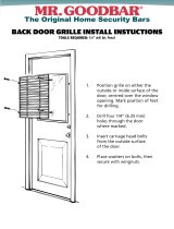
• BE SURE you have enough space. See illustration
below for minimum vertical and horizontal clearance.
• This microwave oven can be installed over gas or
electric cooking products no more than 36 inches
wide.
30" min. cabinet
opening width
30" min. clearance from bottom
of cabinet to cooking surface
or countertop
13 -
9
/
16
"min.microwaveoven
to cooking surface or
countertop
Maximum gas or electric
cooking product width of
36 inches.
(Use templates included
with installation instructions)
Grounded Outlet
(inside upper cabine
t)
Power Supply Cord Hole

Installation Instruction
16021668 Rev. 0 A–4 ©2002 Maytag Appliances Company
Parts, Tools, and Materials
The following parts are supplied with the oven:
NOTE: Depending on ventilation requirements, not all parts will be used.
Backdraft damper / duct connector
(for roof-venting or wall-venting installation)
Not Actual Size ( 2 pieces must be
assembled as shown )
Two self - tapping screws
(for attaching the damper duct connector)
One lock pin and one washer-
One power cord clamp and
One dark-colored mounting screw
One power cord clamp bushing -
(for the cord hole in a metal upper cabinet)
F
our 1/4" x 2" lag screws -
(for wall stud holes)
Two 1/4" x 2" bolts -
(for securing to the upper cabinet)
Two washers -
(for the two upper cabinet bolts)
Four spring toggle heads -
(for the toggle bolts)
Four 1/4" x 3" toggle bolts -
(for drywall holes)
(to hold the power cord)
Actual Size
NOTE: Install at least two lag screws into one 2” X 4” stud and four anchor bolts into the wall.
The mounting area must meet the 150 lbs. weight requirement.
Tools and materials required for installation:
List of tools include: Stud finder or thin nail, Saber saw, Keyhole saw, Electric drill, Phillips and Flat blade
screwdriver, Pencil, Tape measure (metal), Plumb line, Tin snips, Caulking gun, Duct tape, Clear tape, Wood and
Metal drill bits.
NOTE: Use the carton or heavy material for covering the counter top.
NOTE: Ductwork required for installation is not included. All wall and roof caps must have a back-draft damper.

Installation Instruction
©2002 Maytag Appliances Company A–5 16021668 Rev. 0
Preparing Electrical Connection
WARNING
!
To avoid risk of electrical shock, this appliance must
be grounded.
1. Locate grounded electrical outlet for oven in the
cabinet above the oven.
NOTE: Outlet should be on a circuit dedicated to the
microwave oven (120 VAC, 60 Hz) with a
20 Amp fused electrical supply.
NOTE: If proper wall outlet is not present, one must be
installed by a qualified electrician.
2. Power supply cord hole will be cut later when
preparing the wall and upper cabinet.
Grounded Outlet
(inside upper cabine
t)
P
ower Supply Cord Hole
Upper
Cabinet
NOTE: Do not use extension cord. Keep power cord dry
and do not pinch or crush.
Preparing Venting System
Oven may be vented in one of three ways.
NOTE: Do not vent oven into a wall cavity, an attic or an
unused area.
WARNING
!
To avoid risk of fire, personal injury or property
damage, oven must be properly vented.
NOTE: Duckwork needed for outside ventilation is not
included with oven.
Roof-Venting
Oven is located on an outside wall near roof.
Roof Venting
Through-the-roof
3 1/4"x10"
duct
Roof cap
Roof venting
6"
Diameter
round duct
3
1/4" to round
duct transition
Roof cap
Wall Venting
Oven is located on an outside wall of house.
Wall Venting
Wall venting
Through-the-wa
ll
Wall cap
31/4"x10"
duct
3
1/4" to round
duct transition
Wall ca
p
Elbow

Installation Instruction
16021668 Rev. 0 A–6 ©2002 Maytag Appliances Company
Room Venting
Oven is located on an inside wall of house.
Room Venting
NOTE: Remember the following when installing venting.
• Keep length of ductwork and the number of
elbows to a minimum to ventilate oven
efficiently.
• Keep the size of the ductwork the same.
• Do not install two elbows together.
• Use duct tape to seal all joints in the ductwork
system.
• Use caulking to seal exterior wall or roof
opening around the cap.
Standard Fittings
NOTE: If existing ductwork is round, a rectangular-to-
round adapter must be used with a rectangular
3" extension duct installed between the damper
assembly and adapter to prevent the exhaust
damper from sticking.
Ductwork Length
The total length of the ductwork system, including
straight duct, elbows, transitions, and wall or roof cap
must not exceed the equivalent of 140 feet.
For best performance, do not use more than three 90°
elbows and keep the length as short as possible.
Following are standard fittings and their equivalent
length in feet.
1
4567
23
3 1/4"x10"
to 6"=5ft.
90 elbow
=10ft.
45 elbow
=5ft.
31/4"x10"
wall cap
=40ft.
3 1/4"x10"
flat elbow
=10ft.
3 1/4"x10" roof
cap=24ft.
31/4"x10"90
elbow=25ft.
To calculate the equivalent length of each duct piece
used, see examples below.
For 3 1/4"x10" Systems
1-31/4"x10"90 elbow
1-Wall Cap
8 feet straight duct
Total Length
6ft.
2ft.
3 1/4"x10"
90 elbow
wall cap
= 25 ft.
= 40 ft.
= 8 ft.
= 73 ft.
1-transition
2-90 elbows
1-Wall Cap
8 feet straight
Total Length
For 6" Round Systems
2ft.
6ft.90 elbows
transition
wall cap
=5ft
.
=20ft
.
=40ft
.
=8ft
.
=73ft
.

Installation Instruction
©2002 Maytag Appliances Company A–7 16021668 Rev. 0
Preparing Venting Blower
WARNING
!
To avoid risk of electrical shock or personal injury,
disconnect power to unit before working on vent
blower.
NOTE: Do not pull or stretch blower wiring. Pulling or
stretching blower wiring could result in electrical
wiring damage.
Microwave oven is shipped with blower assembly for
roof venting. If wall or room venting installation is
desired, blower assembly must be changed.
1. Remove screws securing mounting plate to oven
cabinet and set side.
2. Replace screws back into oven cabinet.
B
B
Replace screws
into cabinet.
Remove
mounting
plate.
Roof Venting Installation
Blower venting is assembled at the factory for roof
venting. Proceed to “Wall and Upper Cabinet
Installation” section.
Wall Venting Installation
1. Remove blower unit mounting screw and blower
plate screws (save screws for step 8). Remove
blower plate from cabinet.
Blower
plate
Blower unit
mounting screw
B
B
B
lower
unit
2. Carefully lift blower unit out of oven cabinet.
3. Disconnect blower motor terminal plug from wire
harness.
4. Rotate blower unit so exhaust ports face the rear of
the cabinet.
Blowe
r
unit
Exhaust
ports
5. Reconnect blower motor terminal plug, making sure
the wire is under the supporter.
Support
er
Blower
wire
6. Place blower unit back into cabinet. Verify exhaust
ports face towards the rear and are aligned with the
holes in the back of the unit.
Exhaust
ports
7. Remove knockouts marked B (see step 1 for
illustration) from back plate and discard. Be careful
not to distort back plate.
8. Attach blower plate to cabinet with exhaust ports and
blower plate opening aligned. Secure blower unit
with screws that were removed in step 1.
Room Venting Installation (Recirculating)
1. Remove blower unit mounting screw and blower
plate screws (save screws for step 5). Remove
blower plate from cabinet.
Blower
plate
Blower unit
mounting screw
B
B
B
lower
unit
2. Carefully lift blower unit out of oven cabinet.
3. Rotate blower unit 90° so that exhaust ports face the
front of the cabinet.

Installation Instruction
16021668 Rev. 0 A–8 ©2002 Maytag Appliances Company
4. Place blower unit back into cabinet. Verify exhaust
ports face towards the front of the unit.
5. Attach blower plate to cabinet. Secure blower unit
with screws that were removed in step 1.
Preparing Wall and Upper Cabinet
CAUTION
!
To avoid property damage cover countertop or
cooktop by placing a piece of cardboard from the
carton or a heavy piece of material. Do not use
plastic.
• Remove shipping material and parts from inside the
microwave oven.
• Cover countertop or cooktop with a thick protective
covering, to protect it from damage and dirt.
A thick, protective
covering
NOTE: For easy access to wall and upper cabinet,
remove range from wall to allow easier
measuring and drilling.
Preparing Template Placement
1. Find and mark the vertical center line on the back
wall, using a tape measure and plumb line.
2. Find and mark placement of one or two points
indicating stud location on the wall.
• Measure and mark stud location within the area
marked H on the wall template.
• If wall studs cannot be located, consult a local
building contractor.
WARNING
!
To avoid risk of property damage or personal injury,
do not attempt to install microwave oven if wall studs
cannot be located.
3. Align plumb line on wall with center line on the wall
template.
• Verify minimum width is 30" and the distance from
the top of wall template to the range or countertop
is at least 30".
4. Secure wall template to the wall.
• If cabinets are not level, adjust the wall template
to align with cabinet.
• Oven must hang level. If the front edge of the
cabinet is lower than the back edge, adjust wall
template to be level with the cabinet front.
Upper cabinet template
Wall template
5. Measure the bottom of the upper cabinet frame. Trim
the edges A, B, and C on the upper cabinet
template, so template will fit on the bottom of the
upper cabinet. If upper cabinet has a recessed
frame, trim the template to fit inside the recessed
area. Align the centerline of the upper cabinet
template with the centerline on the wall template.
Secure upper cabinet template in place.

Installation Instruction
©2002 Maytag Appliances Company A–9 16021668 Rev. 0
Drilling Holes in the Wall and Upper Cabinet
WARNING
!
To avoid electrical shock or personal injury, be very
careful when drilling holes into the wall. Electrical
wires may be concealed behind the wall covering.
1. Find the points on the wall template labeled D, E, F,
and G. Drill a
3
/16" diameter hole at any points
located over a wall stud. Drill
3
/4" diameter hole at
any point over the wall without studding.
2. Drill holes into studded areas marked H and I on the
wall template using a
3
/16" drill bit. If wall studs are
not located within these areas, drill
3
/4" holes nearest
to the center of the areas as possible.
NOTE: If there are no wall studs within the areas
marked H and I, or behind points marked D, E,
F, and G, do not install microwave oven.
(Consult a building inspector.) There must be at
least one wall stud in the marked areas.
3. Drill a
3
/8" hole at points J, K, and N on upper cabinet
template.
NOTE: If the bottom of the cabinet is recessed
3
/4" or
more, filler block (not included) will be required
to provide additional support for the bolts.
C
abinet front
Filler block Cabinet
bottom she
lf
• Mark the center of each filler block needed
and drill a
3
/8" hole through the block.
• Align the filler blocks with openings in the top
of the microwave oven cabinet and attach to
the cabinet with tape.
Fille
r
bloc
k
4. Cut or drill a 2" hole at the area marked M, for power
cord access into upper cabinet.
NOTE: If upper cabinet is metal, cover the edges of the
hole to prevent damage to the power cord.
WARNING
!
To avoid electrical shock or personal injury, cover
edges on metal cabinet to prevent damage to power
cord.
5. Cut out the venting area required for installation.
• Roof vented: Cut out shaded area marked L on
the upper cabinet template.
• Wall vented: Cut out shaded area marked O on
the wall template.
• Room vented: Proceed to “Installing Mounting
Plate” section.
6. Use caulking compound to seal the exterior wall or
roof opening around the wall or roof cap.
Installing Mounting Plate
1. Remove templates from wall and upper cabinet.
Mounting plate
Damper must be on top of
tab for proper venting.
NOTE: If venting through the wall, verify alignment of
damper on the rear of the mounting plate moves
freely.
2. Place toggle bolts through mounting plate holes
where
3
/4" holes were drilled. Attach spring toggle
head on each toggle bolt.
T
oggle bolt
Mounting plate
Spring
toggle hea
d
3. Place mounting plate against the wall aligning toggle
bolts with holes.
Support tabs

Installation Instruction
16021668 Rev. 0 A–10 ©2002 Maytag Appliances Company
NOTE: Leave at least the wall thickness of space to
allow spring toggle head to open once placed
into the wall.
Wall
Mounting plate
T
oggle bolt
Spring
toggle head
4. Locate wall stud holes and insert lag screws through
mounting plate and into
3
/16" holes, do not tighten .
L
ag screw
Mounting pate
5. Insert toggle bolts through wall surface and tighten.
Tighten lag screws at this point also.
6. Slide washer onto the lock pin and place inside the
upper cabinet for further use.
L
ock pin
Wash
er
Attaching Oven to the Wall
WARNING
!
This unit is an excessive weight hazard, which can
cause personal injury or property damage. Two or
more people are required to lift unit. To prevent injury
or property damage, use proper lifting and carrying
techniques when moving unit.
1. Carefully lift microwave oven and hang it on support
tabs at the bottom of the mounting plate. Reaching
through upper cabinet, thread power supply cord
through cutout in the bottom of the upper cabinet.
Power cord
Power cor
d
hole
2. Rotate the microwave upward until oven is against
the bottom of the upper cabinet or cabinet frame.
3. Drop the lock pin and washer assembly into hole N,
and push the pin downward as far as it will go.
Washer
Lock pin
4. Insert 3" X
1
/4" bolts and washers down into holes J
and K. Tighten the bolts until the gap between the
microwave and cabinet has closed.
5. Remove the lock pin and washer. If wall or roof
venting installation is used, skip to step 8.

Installation Instruction
©2002 Maytag Appliances Company A–11 16021668 Rev. 0
6. Roof-vented installation: Align the damper/duct
connector with the vent on top of the microwave
oven. Damper should be on top of tab. Use two
tapping screws (bright-colored) to attach damper/
duct connector to the microwave oven.
damper
NOTE: Damper/duct connector must be attached to
microwave oven after microwave oven is
installed.
7. Roof venting installation: Install ductwork through the
vent opening in the upper cabinet. Complete the
venting system through the roof according to the
method needed. See, Preparing Venting System
section. Use caulking to seal the exterior roof
opening around the exhaust cap.
8. Use the power supply cord clamp to bundle the
power supply cord. Install the power supply cord
clamp inside the cabinet.
duct
powe
r
suppl
y
cord
clamp
9. Grasp filter screen with one hand holding the ring
and the other hand holding the opposite end. Insert
the end of the filter screen without ring into the
opening and slide towards the side of the microwave
oven. Insert ring end of filter screen into the opening
and slide entire screen towards the center of the
microwave until screen is securely in position.
Repeat for other filter screen.
10.Plug in the power supply cord.

Installation Instruction
16021668 Rev. 0 A–12 ©2002 Maytag Appliances Company
This page intentionally left blank.

©2002 Maytag Appliances Company B–1 16021668 Rev. 0
Appendix B

16021668 Rev. 0 B–2 ©2002 Maytag Appliances Company
For best performance and safety, keep the oven clean
inside and outside. Take special care to keep the inner
door panel and the oven front frame free of food or
grease build-up.
Never use abrasive cleaners or pads. Wipe the
microwave oven inside and out, including the hood
bottom cover, with a soft cloth and a warm (not hot) mild
detergent solution. Then rinse and wipe dry. Use a
chrome cleaner and polish on chrome, metal, and
aluminum surfaces. Wipe spatters immediately with a
wet paper towel, especially after cooking chicken or
bacon. Clean your oven weekly or more often, if needed.
Cleaning the Grease Filters
The grease filters should be removed and cleaned often,
at least once a month.
1. To remove grease filters, slide each filter to the side.
Pull filters downward and push to the other side. The
filter will drop out.
2. Wash in dishwasher or soak grease filters in hot
water and a mild detergent. Rinse well and shake to
dry. Do not use ammonia. The ammonia will darken
the filter.
3. To reinstall the filters, slide it into the side slot, then
push up and toward oven center to lock.
CAUTION
!
To avoid risk of property damage, do not operate the
hood vent system without the filters in place.
Charcoal Filter Replacement
If the oven is vented inside the room, the charcoal filter
should be replaced every 6 to 12 months, and more
often if necessary. The charcoal filter cannot be cleaned.
To order a new charcoal filter, contact the Parts Depart-
ment at your nearest Authorized Service Center.
Order Charcoal Filter Kit #: MVHRK3.
1. Disconnect power to oven.
2. Remove the two vent grille mounting screws.
(2 middle screws)
3. Tip the grille forward, then lift out.
Care and Cleaning

©2002 Maytag Appliances Company B–3 16021668 Rev. 0
4. Remove old filter.
5. Slide new charcoal filter into place. The filter should
rest at the angle shown.
6. Slide the bottom of the vent cover into place. Push
the top until it snaps into place. Replace the
mounting screws. Turn the power back on and set
the clock.
Cooktop/Night Light Replacement
1. Unplug the oven or turn off power at the main power
supply.
2. Remove the bulb cover mounting screws.
3. Replace bulb(s) with 30 or 40 watt appliance bulb(s).
4. Replace bulb cover.
5. Turn the power back on at the main power supply.
Oven Light Replacement
1. Unplug oven or turn off power at the main power
supply.
2. Remove the vent cover mounting screws. (2 middle
screws)
3. Tip the cover forward, then lift out to remove.
4. Remove bulb holder mounting screw.
5. Lift up the bulb holder.
6. Replace bulb with a 30 or 40 watt appliance bulb.
7. Replace the bulb holder and mounting screw.
8. Slide the bottom of the vent cover into place. Push
the top until it snaps into place. Replace the
mounting screws. Turn the power back on at the
main power supply.
Care and Cleaning
/