Page is loading ...

USER MANUAL
AUS
AFTER SALES SUPPORT
[email protected]1300 663 907
MODEL: DY160121, 06/2019, 56434
STEPS SMART
LADDER STABILITY
SENSOR

3
After Sales Support
1300 663 907
Model Number DY160121
[email protected]om.au
AUS
Warranty Details
The product is guaranteed to be free from defects in workmanship and parts for a period
of 12 months from the date of purchase. Defects that occur within this warranty period, under
normal use and care, will be repaired, replaced or refunded at our discretion. The benets
conferred by this warranty are in addition to all rights and remedies in respect of the product
that the consumer has under the Competition and Consumer Act 2010 and similar state and
territory laws.
Our goods come with guarantees that cannot be excluded under the Australian Consumer Law.
You are entitled to a replacement or refund for a major failure and for compensation
for any other reasonably foreseeable loss or damage. You are also entitled to have the goods
repaired or replaced if the goods fail to be of acceptable quality and the failure
does not amount to a major failure.
AFTER SALES SUPPORT
MODEL: DY160121 PRODUCT CODE: 56434 06/2019
REGISTER YOUR PURCHASE ATwww.aldi.com.au/en/about-aldi/product-registration/TO KEEP UP-TO-DATE WITH IMPORTANT PRODUCT INFORMATION
1300 663 907
AUS
customercare@winplus.com.au
STEP SMART LADDER STABILITY SENSOR
YEAR WARRANTY
1
Contents
Warranty Details 2
Welcome 4
General Safety Instructions 4
Pack Contents 5
Features 5
Technical Specications 5
Product Overview 5
Before First Use 6
Instructions 6
Insert Batteries 6
Basic Ladder Safety 7
General Ladder Safety 7
Using your ladder 7
Function Overview 8
Visual Representation of X Axis or a Sideways Lean 8
Visual Representation of Z Axis or Ladder Tilt 9
Set Up Overview 10
Set Up 11
Operation 13
Using the Step Smart Ladder Stability Sensor 13
Display Functions 14
Repair and Refurbished Goods or Parts Notice 15
Warranty Details

4
5
Af
Af
ter
ter
Sales Suppo
Sales Suppo
rt
rt
1300 663 907 1300 663 907
Model Number DY160121
Model Number DY160121
[email protected]om.au
[email protected]om.au
AUS
AUS
Congratulations on choosing to buy a WORKZONE® product. By doing so
you now have the assurance and peace of mind that comes with purchasing
a product made by one of the leading manufacturers. All products brought
to you by WORKZONE® are manufactured to the highest standards of
performance and safety and, as part of our philosophy of customer service
and satisfaction, are backed by our comprehensive 1 year warranty. We
hope you will enjoy using your purchase for many years to come.
Welcome
General Safety Instructions
Read this manual thoroughly before rst use and keep it in a safe place for
future reference, along with the warranty card, purchase receipt and carton.
Follow all instructions and take notice of all warnings to reduce the risk of
re or electric shock.
• Carefully follow all instructions for assembly and mounting
• The device contains no serviceable parts. Opening the product will void your
warranty (aside from battery compartment)
• Take care of the device, rough use and mistreatment may aect electronic
components
• Always exercise caution when operating any electronic device
• Keep away from liquids, oils, petrol, and all chemicals
• Turn o when not in use
• Supervise young children to ensure they do not play with the product
• This product is intended for domestic use only, and is not intended for
commercial, industrial or trade use
IMPORTANT NOTE:
The product is a warning device only, it will alarm and notify you if your ladder
moves, it will not:
• Prevent falling from a ladder
• Ensure proper use of a ladder
• Detect faults or any damage to a ladder
• Provide any stability to a ladder
The device can only take accurate readings if set up correctly, so ensure you
read the instructions in full before use.
Pack Contents
• 1 x Step Smart Ladder Stability Sensor Unit (assembled with mounting
bracket)
• 3 x AA Activ Energy Batteries
• 1 x Instruction Manual (Not Shown)
• 1 x Getting Started Guide (Not Shown)
• 1 x Warranty Card (Not Shown)
Voltage: 4.5V (3x1.5V AA) DC
Dimension: 325 x 78 x 55mm (with bracket)
Features
Technical Specifications
• Universal application - ts to most ladders
• Telescopic mounting bracket with rubberised grip ends
• Precision sensors detect changes in angle of ladder
• LED display with warning lights
• Audible alarm to alert you when the ladder angle changes
• Durable aluminum housing
2 3 4 5 61
8 97
1. ON/OFF button
2. LED level indicators
3. Power indicator
4. Battery cover
5. Bracket locking clip*
6. Telescopic bracket and adjustable pole
7. Mounting feet
8. SET level button
9. Speaker
Product Overview
*Bracket has been reversed for illustrative purposes

6
7
Af
Af
ter
ter
Sales Suppo
Sales Suppo
rt
rt
1300 663 907 1300 663 907
Model Number DY160121
Model Number DY160121
[email protected]om.au
[email protected]om.au
AUS
AUS
Instructions
• Unpack your Step Smart Ladder Stability Sensor device and check that you
have received all the components according to Pack Contents on page 5
• Remove any packaging material and promotional labels before using your
Step Smart Ladder Stability Sensor device for the rst time
• Plastic wrapping can be a suocation hazard for babies and young children,
so ensure all packaging materials are out of their reach and disposed of safely
• Ensure you have read and understood all instructions and warnings in this
manual before use. Refer to the Product Overview on page 10 to familiarize
yourself with the product and identify all parts
Insert Batteries
1. Unscrew the battery cover, and insert the batteries (provided), noting the
polarity marked on the back of the device
WARNING: Do not mix old and new batteries. Do not mix Alkaline, Standard
(Carbon - Zinc), Or Rechargeable (Nickel - Cadmium) batteries
• Non-rechargeable batteries are not to be recharged
• Rechargeable batteries are to be removed from the appliance before being
charged
• Batteries are to be inserted with the correct polarity
• Exhausted batteries are to be removed from the appliance and safely
disposed of
• If the appliance is to be stored unused for a long period, the batteries should
be removed
• The supply terminals are not to be short-circuited
2. Screw the battery cover back into place
3. Press the Power button to check that you have installed the batteries
correctly; the LED’s will light up and begin ashing. Turn OFF by holding
down the Power button once you have conrmed the batteries are
installed correctly. There will be three short beeps
Before First Use
IMPORTANT NOTE:
• Always refer to the product manual or instructions provided with your ladder
• The Step Smart Ladder Stability Sensor is a warning device only. It does not
replace general ladder safety and should only be used in conjunction with
safe ladder use
• Correct mounting and Set Up is an integral part of using the Step Smart
Ladder Stability Sensor device
General Ladder Safety
Setting up your ladder
• Your ladder should be set up on a rm footing and secured against
slippage
• Straight ladders should be erected at an angle of approximately 76° (4:1)
to the ground or 14° at the top
• Step ladders need to be opened fully and ladder locks or braces engaged
before climbing
• Upper and lower sections of extension ladders should be overlapped to
provide stability
• Weight of the ladder should be placed squarely on the ladder feet and not
on the rungs
• Two or more people should be used to erect long or heavy ladders
Using your ladder
• Three points of contact must be maintained at all times when climbing
• Only one person should be on the ladder at any one time and the weight
limit of ladder should not be exceeded
• Do not carry tools in your hands while climbing
• Hold onto rungs rather than side rails for more safety if a foot slips
• Wear appropriate footwear
• Work from within the ladder width, center of body (i.e. belt buckle) should
not be further than the side rail. Do not overreach as overreaching can
lead to the ladder tipping sideways
• Face the ladder when going up or down or when working from it
• Stand on a rung that is at least 900mm from the top of a single or
extension ladder
• Stand on or below the second tread below the top plate of any stepladder
Basic Ladder Safety

8
9
Af
Af
ter
ter
Sales Suppo
Sales Suppo
rt
rt
1300 663 907 1300 663 907
Model Number DY160121
Model Number DY160121
[email protected]om.au
[email protected]om.au
AUS
AUS
<1.5º
1.5º-2.7º
2.7º-5º
5º+
1
Flashing Green
<1.5º
Slow Flashing Red
Slow Beep
1.5º-2.7º
2
Rapid Flashing Red
Rapid Beep
2.7º-5º
3
Two Solid Red Lines
Constant Alarm
5º+
4
1
2
3
4
5º-14º
Flashing Green
5º-14º
Two Flasing Red Lines
Rapid Beep
Change of 1.5º
from set position
Two Solid Red Lines
Constant Alarm
Wall
Side
Ladder
View
Change of 2.7º
from set position
1.5º
1.5º
2.7º
2.7º
1
1
2
2
3
3
Function Overview
Visual Representation of X Axis or a Sideways Lean
This visual shows the degree of change required to initiate the alarm when the
ladder moves sideways.
NOTE: This representation is not to scale and is for a visual reference only
Visual Representation of Z Axis or Ladder Tilt
This visual shows the degree of change required to initiate the alarm when the tilt
of the ladder changes.
NOTE: This representation is not to scale and is for a visual reference only
Function Overview

10
11
Af
Af
ter
ter
Sales Suppo
Sales Suppo
rt
rt
1300 663 907 1300 663 907
Model Number DY160121
Model Number DY160121
[email protected]om.au
[email protected]om.au
AUS
AUS
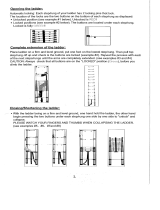
Set Up
Set Up
NOTE: The Step Smart Ladder Stability Sensor unit has been designed to t to
most ladders, however in some cases you may not be able to mount the unit to
your ladder in which case, do not attempt to use the Step Smart Ladder Stability
Sensor device
1. Ensure your ladder is set up as per your user manual and is on a level
surface
2. Select a gap between the rungs where you can mount the device
horizontally
NOTE: If possible, we recommend that the unit is mounted around eye level for
better visibility
3. Unclip the red telescopic bracket clip to allow the size of the bracket to
be adjusted
4. Extend the right-hand bracket plate until
both bracket plates push against the
inside wall of your ladder and close the red
telescopic bracket clip
5. Slowly push the unit upwards so the device
is ush to the underside of a rung, ensure
there is a tight t. As most ladders taper
upwards, it will t more securely as you push
it up
NOTE: The device must be installed directly under
a ladder rung to ensure it does not become an
obstruction with your feet when climbing up or
down the ladder
6. Press the Power button to enter Set Up
Mode, you will hear one short beep. In Set
Up Mode, the Red and Green LEDs will ash
to indicate level, but no alarm will sound
NOTE: Refer to page 14 for more details on the
Display Functions
Set Up Overview
NOTE: The Step Smart Ladder Stability Sensor is a warning device and is
intended to assist with set up and early notication that your ladder has moved
with the aid of visual and audible warnings. The Step Smart Ladder Stability
Sensor does not replace general ladder safety
1. Insert batteries into the Step Smart Ladder Stability Sensor
2. Set up your ladder following your ladder’s user manual
3. Mount the Step Smart Ladder Stability Sensor onto your ladder – see Set
Up on Page 11
4. Turn the Step Smart Ladder Stability Sensor on, check your ladder is level
using Set Up Mode
5. The Step Smart Ladder Stability Sensor’s LEDs will ash to indicate level
but no alarm will sound
6. Press Set to start Active Mode and begin safe use of your ladder
7. The Step Smart Ladder Stability Sensor will now check for any change in
the stability of your ladder

12
13
Af
Af
ter
ter
Sales Suppo
Sales Suppo
rt
rt
1300 663 907 1300 663 907
Model Number DY160121
Model Number DY160121
[email protected]om.au
[email protected]om.au
AUS
AUS
Set Up
7. To Set Up your device you may need to adjust the position of your ladder
or even the tment of your device
8. When you have either Green or Red Flashing lights press SET to enter
Active Mode. You will hear 3 conrmation beeps if set up is successful
NOTE:
• Active Mode can be set if:
- The LED lights are Green or Flashing Red - note if set when Flashing Red the
unit will alarm in Active Mode to remind you that your ladder is not level
• Active Mode cannot be set if:
- The LED lights are Two Solid Red Lines – this is too far from level and unsafe
for use
Operation
Using the Step Smart Ladder Stability Sensor
NOTE: The Step Smart Ladder Stability Sensor is a warning device and is
intended to assist with set up and early notication that your ladder has moved
with the aid of visual and audible warnings. The Step Smart Ladder Stability
Sensor does not replace general ladder safety
1. Once the Step Smart Ladder Stability Sensor is in Active Mode it will
check for any change in the stability of the ladder. Refer to page 14 to
reference the Display Functions
2. Slow Red Flashing Lights with Slow Caution Beeping or Rapid Flashing
Lights with Rapid Beeping indicate minor changes in the stability of
the ladder. This occurs when the ladder and therefore the device, have
moved. This alarm will notify the user of a small change to the level
of your ladder, in this case review your surroundings for any changes,
by leaning safely you may be able to correct the level of your ladder,
if the alarm continues to sound the user should dismount the ladder
immediately to re-set the ladder to level
3. Two Solid Red Lights and a Constant Alarm Sound indicate signicant
change to the stability of the ladder. This alarm will notify the user of a
substantial change to the level of your ladder, in this instance, the user
should dismount the ladder immediately.
It is recommended that you review your
surroundings for any changes should the
alarm continue
4. To power OFF your Step Smart Ladder
Stability Sensor device, press and hold the
ON/OFF button for 3 seconds then release,
you will hear 3 fast beeps and the device will
power o
NOTE:
• The device will automatically turn o:
- If left in Set Up Mode for more than 10 minutes
- If left in Active Mode for 8 hours without any change to the angle
• The device may alarm as you climb or dismount the ladder
- Depending on the weight of your step and the strength of your ladder
the device may alarm on each step, if this happens climb or dismount the
ladder slowly to ensure the alarm is due to heavy stepping rather than
movement of the ladder.

14
After Sales Support
1300 663 907
Model Number DY160121
[email protected]om.au
AUS
Display Functions
DISPLAY STATUS SOUND
Flashing Green Can be Set to Active Mode
Device is Level
X Axis, Sideways Lean: Within
+/-1.5°
Z Axis, Tilt: Between 5°-14°
Set Up Mode:
No sound
Active Mode:
No sound
Slow Flashing Red Can be set to Active Mode
Use with Caution
X Axis, Sideways Lean:
Between 1.5° - 2.7°
Z Axis, Tilt: Between 5°-14°
Set Up Mode:
No sound
Active Mode:
Slow beep
Rapid Flashing Red
Can be set to Active Mode
Use with Caution
X Axis, Sideways Lean:
Between 2.7°- 5°
Z Axis, Tilt: Between 5°- 14°
Set Up Mode:
No sound
Active Mode:
Rapid beep
Two Flashing Red Lines Only shows in Active Mode
Z Axis, Tilt: Change of 1.5º to
2.7º from set position
Active Mode:
Rapid beep
Two Solid Red Lines Active Mode Not Possible
/ Dismount Ladder when
Safe
X Axis, Sideways Lean: Over 5°
Z Axis, Tilt: More than 2.7º
from set
Set Up Mode:
No sound
Active Mode:
Constant Alarm
Solid Green Battery Light
Device is on and batteries
are suciently charged
No sound
Flashing Green Battery Light
Batteries are close to end of
life and need to be replaced
No sound
Repair and Refurbished Goods
or Parts Notice
Unfortunately, from time to time, faulty products are manufactured which need to be returned
to the Supplier for repair.
Please be aware that if your product is capable of retaining user-generated data (such asles
stored on a computer hard drive, telephone numbers stored on a mobile telephone, songs
stored on a portable media player, games saved on a games console or les stored on a USB
memory stick) during the process of repair, some or all of your stored data may be lost.
We recommend you save this data elsewhere prior to sending the product for repair.
You should also be aware that rather than repairing goods, we may replace them with
refurbished goods of the same type or use refurbished parts in the repair process.
Please be assured though, refurbished parts or replacements are only used where they
meet ALDI’s stringent quality specications.
If at any time you feel your repair is being handled unsatisfactorily, you may escalate your
complaint. Please telephone us on1300 663 907 or write to us at:
Winplus Australasia
PO Box 537 Bayswater Business Centre, Victoria, Australia
1300 663 907 - Hours: Mon-Fri 8:30am - 6:00pm AEST
customercare@winplus.com.au
AFTER SALES SUPPORT
1300 663 907
AUS
customercare@winplus.com.au
YEAR WARRANTY
1
STEP SMART LADDER STABILITY SENSOR
MODEL: DY160121 PRODUCT CODE: 56434 06/2019
Repair and Refurbished
Goods or Parts Notice
Operation
or
or

/