Page is loading ...

APPLICANT: MOTOROLA SOLUTIONS EQUIPMENT TYPE: ABZ89FC5827
109AB-5827
EXHIBIT D
User Information
User Information
Tune-up and user / operational manual information are provided in the following exhibits.
EXHIBIT DESCRIPTION
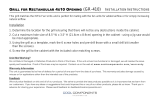
D1 Tune-Up Procedure
D2 User / Operational Manual

APPLICANT: MOTOROLA SOLUTIONS EQUIPMENT TYPE: ABZ89FC5827
109AB-5827
EXHIBIT D1
User Information
Tune-Up Procedure
Aside from the 3
rd
party cavity combiners, there is no field tune-up procedure. All adjustments are software
controlled and are pre-set at the factory. Certain station operating parameters can be changed via man-machine
interface (MMI) commands, within predetermined limits. Examples include transmit / receive operating frequencies
and transmitter power level.
For information on tuning the cavity combiners, which is required only if replaced in the field, please refer to the
User / Operational Manual.

APPLICANT: MOTOROLA SOLUTIONS EQUIPMENT TYPE: ABZ89FC5827
109AB-5827
EXHIBIT D2
User Information
Operational or User’s Manual
The manual should include instruction, installation, operator, or technical manuals with required ‘information to the
users’. This manual should include a statement that cautions the user that changes or modifications not expressly
approved by the party responsible for compliance could void the user’s authority to operate the equipment. The
manual shall include RF Hazard warning statements, if applicable.
This product is installed in restricted access locations only, thus only authorized service personnel have access to
the product. As such, a high level User’s Installation / Operating instruction manual for the product is not
published.
Content from the document “MTS LITE, MTS 2 AND MTS 4 INSTALLATION, CONFIGURATION AND
BASIC SERVICE MANUAL” (part number 6802800U74-AD, September 2014) has been included as part of this
filing package.
Due to space constraints, the full electronic version of this manual is not included in its entirety. The following
chapters have been removed from the full document as these chapters are not intended for the general ‘user’:
Chapter 3: Site Preparation
Chapter 4: Hardware Installation
Chapter 5: Interconnection and Internal Cabling
Chapter 6: Configuration and Testing
Chapter 13: MTS Troubleshooting
Upon request, published manuals will be sent to the commission and/or telecommunication certification body
(TCB). All of the descriptions, block diagrams, and schematics that are included in this filing package are current
as of the package submittal date.

MTS LITE, MTS 2 AND MTS
4 INSTALLATION,
CONFIGURATION AND
BASIC SERVICE MANUAL
DIMETRA
™
Dimetra IP Scalable (DIPS)
Dimetra IP Compact (DIPC)/Scalable Dimetra IP (SDIP)
Dimetra IP Micro/Dimetra IP LiTE
September 2014
*6802800U74*
6802800U74-AD
©
2014 Motorola Solutions, Inc. All rights reserved
Applicant: Motorola Solutions
Equipment Type: ABZ89FC5827 / 109AB-5827
Exhibit D2

Applicant: Motorola Solutions
Equipment Type: ABZ89FC5827 / 109AB-5827
Exhibit D2

Copyrights
The Motorola products described in this document may include copyrighted Motorola computer programs. Laws in
the United States and other countries preserve for Motorola certain exclusive rights for copyrighted computer
programs. Accordingly, any copyrighted Motorola computer programs contained in the Motorola products described
in this document may not be copied or reproduced in any manner without the express written permission of Motorola.
©
2014 Motorola Solutions, Inc. All Rights Reserved
No part of this document may be reproduced, transmitted, stored in a retrieval system, or translated into any language
or computer language, in any form or by any means, without the prior written permission of Motorola Solutions, Inc.
Furthermore, the purchase of Motorola products shall not be deemed to grant either directly or by implication,
estoppel or otherwise, any license under the copyrights, patents or patent applications of Motorola, except for the
normal non-exclusive, royalty-free license to use that arises by operation of law in the sale of a product.
Disclaimer
Please note that certain features, facilities, and capabilities described in this document may not be applicable to or
licensed for use on a particular system, or may be dependent upon the characteristics of a particular mobile subscriber
unit or configuration of certain parameters. Please refer to your Motorola contact for further information.
Trademarks
MOTOROLA, MOTO, MOTOROLA SOLUTIONS, and the Stylized M Logo are trademarks or registered
trademarks of Motorola Trademark Holdings, LLC and are used under license. All other trademarks are the property
of their respective owners.
European Union (EU) Waste of Electrical and Electronic Equipment (WEEE)
directive
The European Union's WEEE directive requires that products sold into EU countries must have the crossed out
trash bin label on the product (or the package in some cases).
As defined by the WEEE directive, this cross-out trash bin label means that customers and end-users in EU countries
should not dispose of electronic and electrical equipment or accessories in household waste.
Customers or end-users in EU countries should contact their local equipment supplier representative or service centre
for information about the waste collection system in their country.
3 | Copyrights
6802800U74-AD | September 2014 | Send Feedback
Applicant: Motorola Solutions
Equipment Type: ABZ89FC5827 / 109AB-5827
Exhibit D2

Applicant: Motorola Solutions
Equipment Type: ABZ89FC5827 / 109AB-5827
Exhibit D2

CMM Labeling and Disclosure Table
The People’s Republic of China requires that our products comply with China Management Methods (CMM)
environmental regulations. (China Management Methods refers to the Regulation Management Methods for
Controlling Pollution by Electronic Information Products.) Two items are used to demonstrate compliance; the Label
and the Disclosure Table.
The label is placed in a customer visible position on the product. The first of the following examples means that the
product contains no hazardous substances; the second means that the product contains hazardous substances, and has
an Environmental Friendly Use Period (EFUP) of fifty years.
The Environmental Friendly Use Period (EFUP) is the period (in years) during which the Toxic and Hazardous
Substances (T&HS) contained in the Electronic Information Product (EIP) will not leak or mutate causing
environmental pollution, or bodily injury from the use of the EIP.
The Disclosure Table, printed in simplified Chinese, is included with each customer order. An example of a
Disclosure Table (in Chinese) follows:
5 | CMM Labeling and Disclosure Table
6802800U74-AD | September 2014 | Send Feedback
Applicant: Motorola Solutions
Equipment Type: ABZ89FC5827 / 109AB-5827
Exhibit D2

Applicant: Motorola Solutions
Equipment Type: ABZ89FC5827 / 109AB-5827
Exhibit D2

Service Information
Government Technical Support (GTS), EA Solutions Support Centre
The Government Technical Support (GTS), EA Solutions Support Centre provides a remote Technical Support
Service to help customers resolve technical issues and quickly restore networks and systems. This team of highly
skilled professionals is available to customers with current service agreements in place that include the Technical
Support Service. The EA GTS technical experts may be accessed through the EMEA Integrated Call Center either
electronically or using the telephone numbers listed below. If you are unsure whether your current service agreement
entitles you to benefit from this service, or if you would like more information about the Technical Support Service,
contact your local customer support or account manager for further information.
Contact Details
Email: [email protected]
Table 1: List of Telephone Numbers
Country In Country Number to Dial
AUSTRIA 01206091087
DENMARK 043682114
FRANCE 0157323434
GERMANY 06950070204
ITALY 0291483230
LITHUANIA 880 030 828
NETHERLANDS 0202061404
NORWAY 24159815
PORTUGAL 0217616160
RUSSIA 810 800 228 41044
(Alternative 810 800 120 1011)
SAUDI ARABIA 800 844 5345
SOUTH AFRICA 0800981900
SPAIN 0912754787
UNITED KINGDOM 02030 277499
All Other Countries +44 2030 277499
European Systems Component Centre (ESCC)
The European Systems Component Centre provides a repair service for infrastructure equipment. Customers requiring
repair service should contact the Customer Information Desk to obtain a Return Material Authorization number. The
equipment should then be shipped to the following address unless advised otherwise.
Motorola GmbH, European Systems Component Centre, Am Borsigturm 130,13507 Berlin, Germany
Contact Details
• E-Mail: [email protected]
7 | Service Information
6802800U74-AD
| September 2014 |
Send Feedback
Applicant: Motorola Solutions
Equipment Type: ABZ89FC5827 / 109AB-5827
Exhibit D2

• Telephone: +49 (0) 30 66861404
• Telefax: +49 (0) 30 66861426
• Monday – Friday 08:00 am to 06:00 pm (CET)
Parts Identification and Ordering
Request for help in identification of non-referenced spare parts should be directed to the Customer Care Organization
of Motorola’s local area representation. Orders for replacement parts, kits, and assemblies should be placed directly
on Motorola’s local distribution organization or through the Extranet site Motorola Online at https://
emeaonline.motorolasolutions.com.
Updated Versions of Manuals
Verify the current version of the manual at our Extranet site, Motorola Online: https://
emeaonline.motorolasolutions.com.
Your Input
Send questions and comments regarding user documentation to [email protected]
We welcome your feedback on this and other Motorola manuals. To take a short, confidential survey on Motorola
Customer Documentation, go to docsurvey.motorolasolutions.com
or scan the following QR code with your mobile
device to access the survey.
8 | Service Information
Send Feedback | September 2014 | 6802800U74-AD
Applicant: Motorola Solutions
Equipment Type: ABZ89FC5827 / 109AB-5827
Exhibit D2

Document History
Version Description Date
6802800U74–A Initial Edition July 2006
6802800U74–B Minor changes Aug. 2006
6802800U74–C Table 4–4 updated Aug. 2006
Table 4–5 updated and note inserted
Table 5–6 updated
6802800U74–D Service Cable and Connector Box Description section updated Oct. 2006
6802800U74–E Updates throughout the manual Feb. 2007
6802800U74–F Expansion Cabinet updates throughout the manual, and addi-
tion of Expansion Options chapter.
Aug. 2007
6802800U74–G 800 MHz updates throughout the manual. Nov. 2007
6802800U74–H BTS Q108 SPU updates, including the addition of redundant
power connector on the Site Controller.
Mar. 2008
6802800U74–J
• Regulatory CE Labeling Compliance updated
• MTS 4 Outdoor Enclosure on page 403 added
• Added info about Base Radio dekey when Standby SC is
powered on.
• Added info about frequencies in receiver band that can
cause high bit error rate to occur
• Updated FRU number for RX Splitter
June 2008
6802800U74–K
•
Updated MTS site link configuration info in Table 8–9
• Updated RF cabling/Connections for MTS 4 with two
TX/RX antennas and up to one additional RX antenna (Ta-
ble 5–13 and Figure 5–12)
• Revision to FRU numbers for MTS fan and Hybrid
Combiner
• Other minor updates
Dec. 2008
6802800U74–L
• Updated manual with TEDS compatibility.
• Updates to the Power Supply Unit (PSU) DC Input Power.
• Other minor updates throughout the manual.
Apr. 2009
6802800U74–M
• Ethernet Site Link Cabling hardware installation informa-
tion added.
• Ethernet Site Link cabling and interconnection added.
• Configuring Ethernet Site Link added.
June 2009
6802800U74–N
• Ethernet Site Link Retro-fit kit and configurations added.
• Added section MTS LVD Kit Installation to Hardware In-
stallation chapter.
Sep. 2009
6802800U74–P Updated the following sections: July 2010
Table continued…
9 | Document History
6802800U74-AD | September 2014 | Send Feedback
Applicant: Motorola Solutions
Equipment Type: ABZ89FC5827 / 109AB-5827
Exhibit D2

Version Description Date
• 260 MHz additions throughout the manual.
• Updated information on LVD Kit Installation
• Updated MTS 4 Duplexer FB diagram
•
Updated procedure How to configure E1 links
• other minor updates
6802800U74–R Added non-duplexed MTS 2 configurations Sep. 2010
6802800U74–T Added MTS LiTE Dec. 2010
6802800U74–U
• Added Procedure How to Upgrade the ATCC Firmware
• Updated Procedure How to Replace Site Controller Lithium
Battery
June 2011
6802800U74–V
• Added section Tuning the MTCC in a BTS in Tetra Applica-
tion Mode on page 256
• Removed reference to obsolete item (surge arrestor for an
MTS4 in 450 MHz band for TX/RX and/or RX antennas)
• Added warning not to key the base station without a proper
load
• Added New part numbers for duplexer and preselector (sup-
plied by Fingu, replaces Power Wave)
• General Defect Fixing
Mar. 2012
6802800U74–W Updated the following:
• MMI Commands and MTS Modes of Operation on page
203
• Table 41: RF Cabling/Connections for MTS LiTE with One
TX and One RX ant. No Diversity on page 162
• Service Cable and Connector Box Description on page 207
• Setting Base Radio IP on page 217
Station Verification Procedures on page 220
• Added Configuring the Base Radio VSWR on page 220
• Configuring the Base Radio Receiver on page 217
• XHUB Controller – Front Panel Indicators (LED) on page
282
• XHUB Controller – Front Panel Connectors on page 284
• Troubleshooting: General Check of a Site Controller File
on page 318
• Added Ethernet Site Link on page 328.
• Base Radio Alarms on page 333
• Miscellaneous Troubleshooting on page 355
• Field Replaceable Units (FRUs) on page 405
Restoration content moved to the respective Backup And Re-
store Including FRU/FRE manuals (for Dimetra IP Scalable
and Dimetra IP Compact systems) or Service Manual (for Di-
metra IP Micro system).
May 2012
6802800U74–Y
Added:
Dec.2012
Table continued…
10 | Document History
Send Feedback | September 2014 | 6802800U74-AD
Applicant: Motorola Solutions
Equipment Type: ABZ89FC5827 / 109AB-5827
Exhibit D2

Version Description Date
• Verifying and Tuning the Receiver RSSI Levels on page
224
Updated:
• Ethernet Site Link on page 328
• Site Controller – Front Panel Indicators (LED)
on page
267
6802800U74–AA
Added:
• Encrypted Ethernet Site Links on page 331
• Verifying Encryption Capability on page 332
Updated:
• Verifying and Tuning the Receiver RSSI Levels on page
224
Feb. 2013
6802800U74–AB Updated the following:
• Encrypted Ethernet Site Links on page 331
• Verifying Encryption Capability on page 332
• Field Replaceable Units for MTS LiTE on page 405
• Field Replaceable Units for MTS 2 on page 407
• Field Replaceable Units for MTS 4 on page 409
• Miscellaneous Troubleshooting on page 355
Mar. 2014
6802800U74–AC Updated:
• RF Cabling – MTS 4, No Diversity on page 172
July 2014
6802800U74–AD Added:
• Resetting the RTC Battery Status on page 275
Updated:
• Checking if the Site Controller Lithium Battery Needs
Changing on page 276
• Replacing the Site Controller Lithium Battery on page 276
Sept. 2014
Document History | 11
6802800U74-AD | September 2014 | Send Feedback
Applicant: Motorola Solutions
Equipment Type: ABZ89FC5827 / 109AB-5827
Exhibit D2

Applicant: Motorola Solutions
Equipment Type: ABZ89FC5827 / 109AB-5827
Exhibit D2

Contents
Copyrights........................................................................................................................................ 3
CMM Labeling and Disclosure Table............................................................................................5
Service Information......................................................................................................................... 7
Document History............................................................................................................................9
List of Figures................................................................................................................................ 23
List of Tables.................................................................................................................................. 29
List of Processes............................................................................................................................. 33
List of Procedures.......................................................................................................................... 35
About MTS LiTE, MTS 2 and MTS 4 Installation, Configuration and Basic Service
Manual....................................................................................................................................... 37
What Is Covered In This Manual?...................................................................................................................... 37
Helpful Background Information
........................................................................................................................ 37
Related Information.............................................................................................................................................37
Icon Conventions.................................................................................................................................................38
Style Conventions................................................................................................................................................39
Regulatory CE Marking Compliance..................................................................................................................39
Chapter 1: MTS Overview.................................................................................... 41
MTS Platform Description.................................................................................................................................. 41
MTS LiTE Components...................................................................................................................................... 42
MTS 2 Components............................................................................................................................................ 43
MTS 4 Components............................................................................................................................................ 45
Expansion Cabinet Components......................................................................................................................... 46
MTS Modules......................................................................................................................................................47
RF Distribution System...........................................................................................................................47
Preselector................................................................................................................................... 47
Duplexer...................................................................................................................................... 48
Post Filter.................................................................................................................................... 48
Cavity Combiners........................................................................................................................48
Hybrid Combiner.........................................................................................................................49
Rx Splitter....................................................................................................................................49
Site Controller Module............................................................................................................................49
XHUB......................................................................................................................................................49
Base Radio Module................................................................................................................................. 50
Base Radio Transceiver...............................................................................................................50
Base Radio Power Amplifier.......................................................................................................50
Power Supply Unit.................................................................................................................................. 50
Backup Battery............................................................................................................................50
Cooling Fans........................................................................................................................................... 50
Chapter 2: General Safety.....................................................................................51
General Safety Precautions................................................................................................................................. 51
Mains Safety........................................................................................................................................................52
Battery Safety......................................................................................................................................................52
Chapter 3: Site Preparation.................................................................................. 55
Contents | 13
Applicant: Motorola Solutions
Equipment Type: ABZ89FC5827 / 109AB-5827
Exhibit D2

Site Planning........................................................................................................................................................55
Site Survey.............................................................................................................................................. 55
Site Selection Considerations..................................................................................................................56
Cabinets Installation Considerations
...................................................................................................................56
MTS LiTE Cabinet Considerations.........................................................................................................56
MTS 2 Cabinet Considerations............................................................................................................... 58
MTS 4 Cabinet Considerations............................................................................................................... 59
Expansion Cabinet Considerations..........................................................................................................61
Antenna Installation Considerations................................................................................................................... 63
Network Interface Installation Considerations....................................................................................................64
MTS Installation Special Considerations............................................................................................................64
Environmental Considerations............................................................................................................................ 64
MTS Installation Electrical Requirements for MTS Site.................................................................................... 65
Applicable Codes and Practices.............................................................................................................. 65
AC and DC Power Supplies.................................................................................................................... 66
Service Current Rating................................................................................................................ 66
AC and DC Current Load............................................................................................................72
Backup Battery............................................................................................................................72
Surge Arrestors........................................................................................................................................72
Power Panel.............................................................................................................................................72
User Alarms, Control Outputs, and Door Alarm.................................................................................................73
Grounding Requirements.................................................................................................................................... 73
Chapter 4: Hardware Installation........................................................................ 75
Installation Overview.......................................................................................................................................... 75
Installation Personnel.............................................................................................................................. 75
Receiving the MTS Equipment............................................................................................................... 75
Installation Prerequisites..................................................................................................................................... 76
Cabinet Transportation........................................................................................................................................76
Safety Considerations..............................................................................................................................77
MTS LiTE and MTS 2 Cabinets Transportation.....................................................................................77
Moving the MTS 4 and Expansion Cabinet............................................................................................ 77
Cabinet Installation..............................................................................................................................................79
Cabinet Bracing Considerations..............................................................................................................80
Floor Mounting Instructions....................................................................................................................80
Installing the Cabinet Using the Mounting Brackets.............................................................................. 80
Installing the Cabinet Using the Mounting Plate.................................................................................... 82
Mounting Plate............................................................................................................................ 82
Installing the Mounting Plate...................................................................................................... 83
Securing Cabinet to a Mounting Plate.........................................................................................84
Wall Fixing..............................................................................................................................................85
Electrical Connections.........................................................................................................................................86
Grounding Connection............................................................................................................................ 86
Grounding the Equipment Cabinet..........................................................................................................88
Battery System Grounding.......................................................................................................... 89
Checking Grounding Connections.............................................................................................. 89
Power Supply Connections..................................................................................................................... 89
-48 VDC Input Power and Backup Battery Charging Connections............................................89
Connecting -48 VDC Power Source to the Equipment Cabinet................................................. 91
100–240 VAC Input Power Connections....................................................................................93
Connecting 100–240 VAC Power Source to Equipment Cabinet...............................................95
Backup Battery Sensor Connections........................................................................................... 96
Connecting the Backup Battery Sensor to the Equipment Cabinet.............................................97
MTS LVD Kit Installation.......................................................................................................... 98
Installing the MTS LVD Kit..................................................................................................... 100
14 | Contents
Applicant: Motorola Solutions
Equipment Type: ABZ89FC5827 / 109AB-5827
Exhibit D2

RF Antenna Connections...................................................................................................................................102
Expansion Cabinet Connections........................................................................................................................106
TX Connections.....................................................................................................................................106
Connections between Site Controller and XHUB Controller...............................................................
107
Power Connection to the XHUB Controllers........................................................................................108
CAN Bus Cabling..................................................................................................................................109
RX Connection......................................................................................................................................109
GPS Connections...............................................................................................................................................110
GPS Site Reference Operation Modes.................................................................................................. 111
Tracking Criteria................................................................................................................................... 112
GPS Start Up......................................................................................................................................... 112
Remote GPS Antenna/Receiver Connection.........................................................................................113
Remote GPS Receiver Requirements........................................................................................114
Remote GPS Receiver Cabling................................................................................................. 114
GPS Antenna Connection......................................................................................................................116
GPS Antenna Line Loss............................................................................................................ 118
GPS Interference Avoidance................................................................................................................. 118
X.21, E1-120Ω Cabling.....................................................................................................................................118
Ethernet Site Link Cabling................................................................................................................................121
Ethernet Site Link Retrofit Kit.............................................................................................................. 122
Connecting Ethernet Site Link Retrofit Kit for MTS 2 (old JP)............................................... 123
Connecting Ethernet Site Link Retrofit Kit for MTS 2 (new JP)..............................................123
Connecting Ethernet Site Link Retrofit Kit for MTS 4.............................................................123
Connecting Ethernet Site Link Retrofit Kit for MTS 4 with Expansion Cabinet (old JP)........124
Connecting Ethernet Site Link Retrofit Kit for MTS 4 with Expansion Cabinet (new JP)...... 124
External Alarm Cabling.....................................................................................................................................124
Performing a Final Check-Out after Installation...............................................................................................127
Checking the Cabinet after Setup..........................................................................................................127
Powering Up the MTS...........................................................................................................................127
Recommended Installation Tools, Parts, and Test Equipment..........................................................................127
Recommended Installation Tools..........................................................................................................128
Recommended Test Equipment.............................................................................................................128
Recommended Parts..............................................................................................................................129
Recommended Torque.......................................................................................................................... 130
Mounting Screws...................................................................................................................................130
Chapter 5: Interconnection and Internal Cabling............................................ 135
AC/DC Power Cabling......................................................................................................................................135
AC/DC Power Cabling – MTS LiTE.................................................................................................... 135
AC/DC Power Cabling – MTS 2...........................................................................................................136
AC/DC Power Cabling – MTS 4...........................................................................................................137
AC/DC Power Cabling – Expansion Cabinet........................................................................................140
User Alarms/Controls, X.21, RGPS, and GPS Cabling.................................................................................... 141
User Alarms/Controls, X.21, RGPS, and GPS Cabling – MTS LiTE.................................................. 142
User Alarms/Controls, X.21, RGPS, and GPS Cabling – MTS 2.........................................................143
User Alarms/Controls, X.21, RGPS, and GPS Cabling –MTS 4..........................................................144
E1 and Ethernet Cabling....................................................................................................................................147
E1 and Ethernet Cabling – MTS LiTE..................................................................................................147
E1 and Ethernet Cabling – MTS 2........................................................................................................ 148
E1 and Ethernet Cabling – MTS 4........................................................................................................ 149
E1 and Ethernet Cabling – Expansion Cabinet..................................................................................... 151
Ethernet Site Link Cabling................................................................................................................................152
Ethernet Site Link Cabling – MTS LiTE.............................................................................................. 153
Ethernet Site Link Cabling – MTS 2.....................................................................................................153
Ethernet Site Link Cabling – MTS 4 with Single Site Controller.........................................................154
Contents | 15
Applicant: Motorola Solutions
Equipment Type: ABZ89FC5827 / 109AB-5827
Exhibit D2

Ethernet Site Link Cabling – MTS 4 with Dual Site Controller........................................................... 157
Ethernet Site Link Cabling – MTS 4 Expansion Cabinet with Single Site Controller......................... 159
Ethernet Site Link Cabling – MTS 4 Expansion Cabinet with Dual Site Controller............................
160
RF Cabling........................................................................................................................................................ 162
RF Cabling – MTS LiTE with One TX and One RX Antenna, No Diversity...................................... 162
RF Cabling – MTS LiTE with One TX/RX Antenna........................................................................... 163
RF Cabling – MTS LiTE with One TX and Two RX Antennas...........................................................164
RF Cabling – MTS 2, No Diversity...................................................................................................... 165
RF Cabling – MTS 2 with One TX Antenna.........................................................................................166
RF Cabling – MTS 2 with One TX/RX Antenna..................................................................................168
RF Cabling – MTS 2 with Two TX/RX Antennas................................................................................170
RF Cabling – MTS 4, No Diversity...................................................................................................... 172
RF Cabling – MTS 4 with One TX/RX Antenna..................................................................................174
RF Cabling – MTS 4 with Two TX/RX Antennas................................................................................176
RF Cabling – MTS 4 with One TX Antenna.........................................................................................178
RF Cabling – Expansion Cabinet with One TX/RX Antenna...............................................................180
RF Cabling – Expansion Cabinet with Two TX/RX Antennas.............................................................184
RF Cabling – Expansion Cabinet with One TX Antenna..................................................................... 187
RF Cabling – Expansion Cabinet with Two TX Antennas................................................................... 190
CAN Bus Cabling..............................................................................................................................................193
CAN Bus Cabling – MTS LiTE ...........................................................................................................193
CAN Bus Cabling – MTS 2.................................................................................................................. 193
CAN Bus Cabling – MTS 4.................................................................................................................. 195
CAN Bus Cabling – Expansion Cabinet............................................................................................... 199
Chapter 6: Configuration and Testing...............................................................203
Setup and Testing Overview............................................................................................................................. 203
Preparing for Configuration and Testing...........................................................................................................203
MMI Commands and MTS Modes of Operation.................................................................................. 203
Logging on to the Site Controller Application through Serial Connection...............................204
Logging on to the Base Radio Application through Serial Connection....................................204
Logging on to the BOOT1 mode...............................................................................................205
Logging on to the Test Application...........................................................................................205
Test Equipment......................................................................................................................................206
Service Cable and Connector Box Description.....................................................................................207
Setting Up Service Terminal................................................................................................................. 209
CAN Bus Configuration....................................................................................................................................209
PSU CAN Bus Commands....................................................................................................................209
Fans CAN Bus Commands................................................................................................................... 210
DPM CAN Bus Commands.................................................................................................................. 210
ATCC CAN Bus Commands................................................................................................................ 211
Other CAN Bus Commands..................................................................................................................211
Configuring and Verifying the Site Controller..................................................................................................211
Setting Up the Site Controller............................................................................................................... 212
E1 Connection Test............................................................................................................................... 212
X.21 Connection Test............................................................................................................................212
Site Reference Check............................................................................................................................ 213
Configuring and Verifying the Base Radio.......................................................................................................213
Base Radio Startup Sequence................................................................................................................213
Base Radio Position and Receivers Selection....................................................................................... 215
Setup and Access to Base Radio Position............................................................................................. 216
Setting and Accessing Base Radio Position Using Test Application........................................216
Setting and Accessing Base Radio Position Using Boot1.........................................................217
Setting Base Radio IP............................................................................................................................217
Configuring the Base Radio Receiver ..................................................................................................217
16 | Contents
Applicant: Motorola Solutions
Equipment Type: ABZ89FC5827 / 109AB-5827
Exhibit D2

Corrective Actions for the Base Radio Receiver Configuration............................................... 218
Configuring the pm_config....................................................................................................... 219
Configuring the Base Radio VSWR......................................................................................................220
Station Verification Procedures
.............................................................................................................220
Verifying the Base Radio Software Revision............................................................................220
Upgrading the Base Radio Test Application Software (Optional)............................................220
Transmitter Verification ...........................................................................................................221
Receiver Verification................................................................................................................ 223
Displaying Base Radio Alarms................................................................................................. 226
Viewing the Transmit Spectrum (Optional)..............................................................................227
Synchronizing Non-Volatile Memory (NVM) Regions........................................................................227
Chapter 7: Radio Frequency Distribution System............................................229
RFDS Theory of Operation............................................................................................................................... 229
CAN Bus............................................................................................................................................... 230
RFDS Frequency Band and Bandwidth................................................................................................ 230
MTS LiTE and MTS 2 RFDS........................................................................................................................... 230
MTS LiTE and MTS 2 Filter Tray........................................................................................................ 231
MTS LiTE / MTS 2 Preselector............................................................................................................ 234
Replacing the MTS LiTE / MTS 2 Preselector......................................................................... 236
MTS LiTE / MTS 2 Duplexer............................................................................................................... 237
Replacing the MTS LiTE / MTS 2 Duplexer............................................................................239
Hybrid Combiner...................................................................................................................................241
Replacing the Hybrid Combiner................................................................................................241
MTS 4 RFDS.....................................................................................................................................................242
MTS 4 Filter Tray..................................................................................................................................242
MTS 4 Preselector.................................................................................................................................244
Replacing the MTS 4 Preselector..............................................................................................246
MTS 4 Duplexer....................................................................................................................................247
Replacing the MTS 4 Duplexer.................................................................................................249
Hybrid Combiner in MTS 4.................................................................................................................. 250
Post Filter.............................................................................................................................................. 250
Replacing the Post Filter........................................................................................................... 251
Cavity Combiner................................................................................................................................... 253
Cavity Combiner - Theory of Operation................................................................................... 254
Replacing the Cavity Combiner................................................................................................ 254
Tuning the MTCC in a BTS in Tetra Application Mode.......................................................... 256
Expansion Cabinet RFDS..................................................................................................................................257
RX Splitter.............................................................................................................................................260
Replacing the Expansion Cabinet RX Splitter.......................................................................... 261
Cavity Combiner................................................................................................................................... 262
Chapter 8: Site Controller...................................................................................263
Site Controller – Theory of Operation.............................................................................................................. 264
Site Controller – Indicators, Switches, and Connectors....................................................................................265
Site Controller – Front Panel.................................................................................................................266
Site Controller – Front Panel Indicators (LED)........................................................................ 267
Site Controller – Front Panel Switches..................................................................................... 269
Site Controller – Front Panel Connectors..................................................................................270
Site Controller Rear Panel.....................................................................................................................271
Site Controller – Rear Panel Connectors...................................................................................271
Site Controller CAN Bus...................................................................................................................................271
Updating CAN Bus TrackID Mapping List.......................................................................................... 274
Site Controller – GPS Module...........................................................................................................................275
Contents | 17
Applicant: Motorola Solutions
Equipment Type: ABZ89FC5827 / 109AB-5827
Exhibit D2
/