E-flite EFLU6350 Owner's manual
- Category
- Remote controlled toys
- Type
- Owner's manual
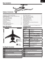
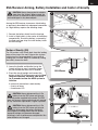
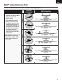
E-flite EFLU6350 is a twin EDF jet with many impressive capabilities. Featuring an 8,800Kv brushless outrunner motor and two 30mm EDF units, this aircraft can reach high speeds and perform a variety of maneuvers. The Spektrum DSMX® 6-Channel Receiver with Dual ESC provides precise control and stability, while the AS3X® technology helps to smooth out the flight and make it easier to fly. With a wing area of 83 sq in and a weight of 6.6 oz, the E-flite EFLU6350 is a great choice for experienced pilots looking for a fast and agile jet.
E-flite EFLU6350 is a twin EDF jet with many impressive capabilities. Featuring an 8,800Kv brushless outrunner motor and two 30mm EDF units, this aircraft can reach high speeds and perform a variety of maneuvers. The Spektrum DSMX® 6-Channel Receiver with Dual ESC provides precise control and stability, while the AS3X® technology helps to smooth out the flight and make it easier to fly. With a wing area of 83 sq in and a weight of 6.6 oz, the E-flite EFLU6350 is a great choice for experienced pilots looking for a fast and agile jet.


-
 1
1
-
 2
2
-
 3
3
-
 4
4
-
 5
5
-
 6
6
-
 7
7
-
 8
8
-
 9
9
-
 10
10
-
 11
11
-
 12
12
-
 13
13
-
 14
14
-
 15
15
-
 16
16
-
 17
17
-
 18
18


E-flite EFLU6350 Owner's manual
- Category
- Remote controlled toys
- Type
- Owner's manual
E-flite EFLU6350 is a twin EDF jet with many impressive capabilities. Featuring an 8,800Kv brushless outrunner motor and two 30mm EDF units, this aircraft can reach high speeds and perform a variety of maneuvers. The Spektrum DSMX® 6-Channel Receiver with Dual ESC provides precise control and stability, while the AS3X® technology helps to smooth out the flight and make it easier to fly. With a wing area of 83 sq in and a weight of 6.6 oz, the E-flite EFLU6350 is a great choice for experienced pilots looking for a fast and agile jet.
Ask a question and I''ll find the answer in the document
Finding information in a document is now easier with AI
Related papers
-
E-flite EFLU6550 Owner's manual
-
E-flite EFLU3750 Owner's manual
-
-
E-flite EFL97500 Owner's manual
-
E-flite EFL01575 Owner's manual
-
-
-
E-flite Extra 300 1.3m Owner's manual
-
E-flite EFL12575 Owner's manual
-
Other documents
-
Horizon Hobby Pawnee Brave Night Flyer AS3X User manual
-
HobbyZone HBZ38500 Owner's manual
-
ParkZone Sukhoi SU-29MM User manual
-
ParkZone Ultra Micro Mosquito Mk VI BNF User manual
-
Mingdiao Lighting RC6737 User manual
-
 Flyzone FLZA3075 Owner's manual
-
Spektrum DXe Transmitter Only Owner's manual
-
-
-
Smart SPMXPSA100 Owner's manual
