Page is loading ...

SSAAFFEETTYY WWAARRNNIINNGG
Only qualified personnel should install and service the equipment. The installation, starting up, and servicing of heating, ventilating, and
air-conditioning equipment can be hazardous and requires specific knowledge and training. Improperly installed, adjusted or altered
equipment by an unqualified person could result in death or serious injury. When working on the equipment, observe all precautions in the
literature and on the tags, stickers, and labels that are attached to the equipment.
May 2017
MMUUAA--SSVVXX000033BB--EENN
Packaged Rooftop Arrangements
For Heating, Cooling and Ventilating Systems
MMooddeell NNuummbbeerrss::
GRAA
GRBA
GRCA
GRDA
AHAA
AHBA
Installation, Operation,
and Maintenance

©2017 Ingersoll Rand
MUA-SVX003B-EN
Introduction
Read this manual thoroughly before operating or servicing this unit.
Warnings, Cautions, and Notices
Safety advisories appear throughout this manual as required. Your personal safety and the
proper operation of this machine depend upon the strict observance of these precautions.
The three types of advisories are defined as follows:
Indicates a potentially hazardous situation which, if not avoided, could result in
death or serious injury.
Indicates a potentially hazardous situation which, if not avoided, could result in
minor or moderate injury. It could also be used to alert against unsafe practices.
Indicates a situation that could result in equipment or property-damage only
accidents.
Important Environmental Concerns
Scientific research has shown that certain man-made chemicals can affect the earth’s naturally
occurring stratospheric ozone layer when released to the atmosphere. In particular, several of the
identified chemicals that may affect the ozone layer are refrigerants that contain Chlorine,
Fluorine and Carbon (CFCs) and those containing Hydrogen, Chlorine, Fluorine and Carbon
(HCFCs). Not all refrigerants containing these compounds have the same potential impact to the
environment. Trane advocates the responsible handling of all refrigerants-including industry
replacements for CFCs and HCFCs such as saturated or unsaturated HFCs and HCFCs.
Important Responsible Refrigerant Practices
Trane believes that responsible refrigerant practices are important to the environment, our
customers, and the air conditioning industry. All technicians who handle refrigerants must be
certified. The Federal Clean Air Act (Section 608) sets forth the requirements for handling,
reclaiming, recovering and recycling of certain refrigerants and the equipment that is used in
these service procedures. In addition, some states or municipalities may have additional
requirements that must also be adhered to for responsible management of refrigerants. Know
the applicable laws and follow them.
WWAARRNNIINNGG
PPrrooppeerr FFiieelldd WWiirriinngg aanndd GGrroouunnddiinngg RReeqquuiirreedd!!
FFaaiilluurree ttoo ffoollllooww ccooddee ccoouulldd rreessuulltt iinn ddeeaatthh oorr sseerriioouuss iinnjjuurryy..
AAllll ffiieelldd wwiirriinngg MMUUSSTT bbee ppeerrffoorrmmeedd bbyy qquuaalliiffiieedd ppeerrssoonnnneell.. IImmpprrooppeerrllyy iinnssttaalllleedd aanndd
ggrroouunnddeedd ffiieelldd wwiirriinngg ppoosseess FFIIRREE aanndd EELLEECCTTRROOCCUUTTIIOONN hhaazzaarrddss.. TToo aavvooiidd tthheessee hhaazzaarrddss,,
yyoouu MMUUSSTT ffoollllooww rreeqquuiirreemmeennttss ffoorr ffiieelldd wwiirriinngg iinnssttaallllaattiioonn aanndd ggrroouunnddiinngg aass ddeessccrriibbeedd iinn
NNEECC aanndd yyoouurr llooccaall//ssttaattee//nnaattiioonnaall eelleeccttrriiccaall ccooddeess..

MUA-SVX003B-EN
3
WWAARRNNIINNGG
PPeerrssoonnaall PPrrootteeccttiivvee EEqquuiippmmeenntt ((PPPPEE)) RReeqquuiirreedd!!
FFaaiilluurree ttoo wweeaarr pprrooppeerr PPPPEE ffoorr tthhee jjoobb bbeeiinngg uunnddeerrttaakkeenn ccoouulldd rreessuulltt iinn ddeeaatthh oorr sseerriioouuss
iinnjjuurryy..
TTeecchhnniicciiaannss,, iinn oorrddeerr ttoo pprrootteecctt tthheemmsseellvveess ffrroomm ppootteennttiiaall eelleeccttrriiccaall,, mmeecchhaanniiccaall,, aanndd
cchheemmiiccaall hhaazzaarrddss,, MMUUSSTT ffoollllooww pprreeccaauuttiioonnss iinn tthhiiss mmaannuuaall aanndd oonn tthhee ttaaggss,, ssttiicckkeerrss,, aanndd
llaabbeellss,, aass wweellll aass tthhee iinnssttrruuccttiioonnss bbeellooww::
•• BBeeffoorree iinnssttaalllliinngg//sseerrvviicciinngg tthhiiss uunniitt,, tteecchhnniicciiaannss MMUUSSTT ppuutt oonn aallll PPPPEE rreeqquuiirreedd ffoorr
tthhee wwoorrkk bbeeiinngg uunnddeerrttaakkeenn ((EExxaammpplleess;; ccuutt rreessiissttaanntt gglloovveess//sslleeeevveess,, bbuuttyyll gglloovveess,,
ssaaffeettyy ggllaasssseess,, hhaarrdd hhaatt//bbuummpp ccaapp,, ffaallll pprrootteeccttiioonn,, eelleeccttrriiccaall PPPPEE aanndd aarrcc ffllaasshh
ccllootthhiinngg)).. AALLWWAAYYSS rreeffeerr ttoo aapppprroopprriiaattee MMaatteerriiaall SSaaffeettyy DDaattaa SShheeeettss ((MMSSDDSS))//SSaaffeettyy
DDaattaa SShheeeettss ((SSDDSS)) aanndd OOSSHHAA gguuiiddeelliinneess ffoorr pprrooppeerr PPPPEE..
•• WWhheenn wwoorrkkiinngg wwiitthh oorr aarroouunndd hhaazzaarrddoouuss cchheemmiiccaallss,, AALLWWAAYYSS rreeffeerr ttoo tthhee
aapppprroopprriiaattee MMSSDDSS//SSDDSS aanndd OOSSHHAA//GGHHSS ((GGlloobbaall HHaarrmmoonniizzeedd SSyysstteemm ooff
CCllaassssiiffiiccaattiioonn aanndd LLaabbeelllliinngg ooff CChheemmiiccaallss)) gguuiiddeelliinneess ffoorr iinnffoorrmmaattiioonn oonn aalllloowwaabbllee
ppeerrssoonnaall eexxppoossuurree lleevveellss,, pprrooppeerr rreessppiirraattoorryy pprrootteeccttiioonn aanndd hhaannddlliinngg iinnssttrruuccttiioonnss..
•• IIff tthheerree iiss aa rriisskk ooff eenneerrggiizzeedd eelleeccttrriiccaall ccoonnttaacctt,, aarrcc,, oorr ffllaasshh,, tteecchhnniicciiaannss MMUUSSTT ppuutt
oonn aallll PPPPEE iinn aaccccoorrddaannccee wwiitthh OOSSHHAA,, NNFFPPAA 7700EE,, oorr ootthheerr ccoouunnttrryy--ssppeecciiffiicc
rreeqquuiirreemmeennttss ffoorr aarrcc ffllaasshh pprrootteeccttiioonn,, PPRRIIOORR ttoo sseerrvviicciinngg tthhee uunniitt.. NNEEVVEERR PPEERRFFOORRMM
AANNYY SSWWIITTCCHHIINNGG,, DDIISSCCOONNNNEECCTTIINNGG,, OORR VVOOLLTTAAGGEE TTEESSTTIINNGG WWIITTHHOOUUTT PPRROOPPEERR
EELLEECCTTRRIICCAALL PPPPEE AANNDD AARRCC FFLLAASSHH CCLLOOTTHHIINNGG.. EENNSSUURREE EELLEECCTTRRIICCAALL MMEETTEERRSS AANNDD
EEQQUUIIPPMMEENNTT AARREE PPRROOPPEERRLLYY RRAATTEEDD FFOORR IINNTTEENNDDEEDD VVOOLLTTAAGGEE..
WWAARRNNIINNGG
TTooxxiicc FFuummeess aanndd FFiibbeerrss!!
IInnssttaallll,, ooppeerraattee aanndd mmaaiinnttaaiinn uunniitt iinn aaccccoorrddaannccee wwiitthh mmaannuuffaaccttuurreerr''ss iinnssttrruuccttiioonnss ttoo aavvooiidd
eexxppoossuurree ttoo ffuueell ssuubbssttaanncceess oorr ssuubbssttaanncceess ffrroomm iinnccoommpplleettee ccoommbbuussttiioonn wwhhiicchh ccoouulldd
rreessuulltt iinn ddeeaatthh oorr sseerriioouuss iillllnneessss.. TThhee SSttaattee ooff CCaalliiffoorrnniiaa hhaass ddeetteerrmmiinneedd tthhaatt tthheessee
ssuubbssttaanncceess mmaayy ccaauussee ccaanncceerr,, bbiirrtthh ddeeffeeccttss,, oorr ootthheerr rreepprroodduuccttiivvee hhaarrmm.. IInnssttaallll aanndd
SSeerrvviiccee tthhiiss pprroodduucctt ttoo aavvooiidd eexxppoossuurree ttoo aaiirrbboorrnnee ppaarrttiicclleess ooff ggllaasssswwooooll ffiibbeerrss aanndd//oorr
cceerraammiicc ffiibbeerrss kknnoowwnn ttoo tthhee SSttaattee ooff CCaalliiffoorrnniiaa ttoo ccaauussee ccaanncceerr tthhrroouugghh iinnhhaallaattiioonn..
Copyright
This document and the information in it are the property of Trane, and may not be used or
reproduced in whole or in part without written permission. Trane reserves the right to revise this
publication at any time, and to make changes to its content without obligation to notify any
person of such revision or change.
Trademarks
All trademarks referenced in this document are the trademarks of their respective owners.
IInnttrroodduuccttiioonn

4
MUA-SVX003B-EN
Receiving Instructions . . . . . . . . . . . . . . . . . . . . . . . . . . . . . . . . . . . . . . . . . . . . . . . . . . . . . . . . . 6
Pre-Installation Instructions. . . . . . . . . . . . . . . . . . . . . . . . . . . . . . . . . . . . . . . . . . . . . . . . . . . 6
General Safety Requirements. . . . . . . . . . . . . . . . . . . . . . . . . . . . . . . . . . . . . . . . . . . . . . . . . . 7
Rigging . . . . . . . . . . . . . . . . . . . . . . . . . . . . . . . . . . . . . . . . . . . . . . . . . . . . . . . . . . . . . . . . . . . . . 9
Combustion Air Considerations . . . . . . . . . . . . . . . . . . . . . . . . . . . . . . . . . . . . . . . . . . . . . . 10
Location . . . . . . . . . . . . . . . . . . . . . . . . . . . . . . . . . . . . . . . . . . . . . . . . . . . . . . . . . . . . . . . . . . . 10
Mounting/Locations. . . . . . . . . . . . . . . . . . . . . . . . . . . . . . . . . . . . . . . . . . . . . . . . . . . . . . . . . 12
Installation. . . . . . . . . . . . . . . . . . . . . . . . . . . . . . . . . . . . . . . . . . . . . . . . . . . . . . . . . . . . . . . . . . . . 13
Installation Clearances . . . . . . . . . . . . . . . . . . . . . . . . . . . . . . . . . . . . . . . . . . . . . . . . . . . . . . 13
Mounting on Field Furnished Supports . . . . . . . . . . . . . . . . . . . . . . . . . . . . . . . . . . . . . . . 13
Mounting on Roof Curb . . . . . . . . . . . . . . . . . . . . . . . . . . . . . . . . . . . . . . . . . . . . . . . . . . . . . 14
Venting . . . . . . . . . . . . . . . . . . . . . . . . . . . . . . . . . . . . . . . . . . . . . . . . . . . . . . . . . . . . . . . . . . . . 22
Duct Connections . . . . . . . . . . . . . . . . . . . . . . . . . . . . . . . . . . . . . . . . . . . . . . . . . . . . . . . . . . . 23
Gas Piping† . . . . . . . . . . . . . . . . . . . . . . . . . . . . . . . . . . . . . . . . . . . . . . . . . . . . . . . . . . . . . . . . 23
Modulating Gas Control (Optional)* . . . . . . . . . . . . . . . . . . . . . . . . . . . . . . . . . . . . . . . . . . 24
Electrical Connections. . . . . . . . . . . . . . . . . . . . . . . . . . . . . . . . . . . . . . . . . . . . . . . . . . . . . . . 25
DX Coil Equipped Units (Optional). . . . . . . . . . . . . . . . . . . . . . . . . . . . . . . . . . . . . . . . . . . . 27
Chilled Water Coil Equipped Units (Optional). . . . . . . . . . . . . . . . . . . . . . . . . . . . . . . . . . 28
Evaporative Cooler Equipped Units (Optional). . . . . . . . . . . . . . . . . . . . . . . . . . . . . . . . . 28
Operation. . . . . . . . . . . . . . . . . . . . . . . . . . . . . . . . . . . . . . . . . . . . . . . . . . . . . . . . . . . . . . . . . . . . . 29
General Information . . . . . . . . . . . . . . . . . . . . . . . . . . . . . . . . . . . . . . . . . . . . . . . . . . . . . . . . 29
Gas Control System. . . . . . . . . . . . . . . . . . . . . . . . . . . . . . . . . . . . . . . . . . . . . . . . . . . . . . . . . 29
Optional Gas Controls . . . . . . . . . . . . . . . . . . . . . . . . . . . . . . . . . . . . . . . . . . . . . . . . . . . 30
Air Handling Requirements and Adjustments . . . . . . . . . . . . . . . . . . . . . . . . . . . . . . . . . 30
Lighting. . . . . . . . . . . . . . . . . . . . . . . . . . . . . . . . . . . . . . . . . . . . . . . . . . . . . . . . . . . . . . . . . . . . 32
Gas Input Adjustment . . . . . . . . . . . . . . . . . . . . . . . . . . . . . . . . . . . . . . . . . . . . . . . . . . . . . . . 32
Pilot Adjustment . . . . . . . . . . . . . . . . . . . . . . . . . . . . . . . . . . . . . . . . . . . . . . . . . . . . . . . . . . . . 33
Primary Air Shutter Adjustment. . . . . . . . . . . . . . . . . . . . . . . . . . . . . . . . . . . . . . . . . . . . . . 33
Controls. . . . . . . . . . . . . . . . . . . . . . . . . . . . . . . . . . . . . . . . . . . . . . . . . . . . . . . . . . . . . . . . . . . . 33
Start-Up . . . . . . . . . . . . . . . . . . . . . . . . . . . . . . . . . . . . . . . . . . . . . . . . . . . . . . . . . . . . . . . . . . . . . . 35
Maintenance. . . . . . . . . . . . . . . . . . . . . . . . . . . . . . . . . . . . . . . . . . . . . . . . . . . . . . . . . . . . . . . . . . 37
General Information . . . . . . . . . . . . . . . . . . . . . . . . . . . . . . . . . . . . . . . . . . . . . . . . . . . . . . . . 37
Filters. . . . . . . . . . . . . . . . . . . . . . . . . . . . . . . . . . . . . . . . . . . . . . . . . . . . . . . . . . . . . . . . . . . . . . 38
Air Blower. . . . . . . . . . . . . . . . . . . . . . . . . . . . . . . . . . . . . . . . . . . . . . . . . . . . . . . . . . . . . . . . . . 39
Blower RPM Adjustment . . . . . . . . . . . . . . . . . . . . . . . . . . . . . . . . . . . . . . . . . . . . . . . . . 39
Table of Contents

MUA-SVX003B-EN
5
Troubleshooting . . . . . . . . . . . . . . . . . . . . . . . . . . . . . . . . . . . . . . . . . . . . . . . . . . . . . . . . . . . . . . 42
Troubleshooting Guide — Air Blower. . . . . . . . . . . . . . . . . . . . . . . . . . . . . . . . . . . . . . . . . 42
Troubleshooting Guide — Electric Motors. . . . . . . . . . . . . . . . . . . . . . . . . . . . . . . . . . . . . 44
Troubleshooting Guide — Fan Assembly . . . . . . . . . . . . . . . . . . . . . . . . . . . . . . . . . . . . . 46
Troubleshooting Guide — DX Cooling Coil . . . . . . . . . . . . . . . . . . . . . . . . . . . . . . . . . . . . 47
Troubleshooting Guide — Chilled Water Cooling Coil . . . . . . . . . . . . . . . . . . . . . . . . . . 48
Unit Net & Ship Weights . . . . . . . . . . . . . . . . . . . . . . . . . . . . . . . . . . . . . . . . . . . . . . . . . . . . . . 49
Double Wall Construction Adder . . . . . . . . . . . . . . . . . . . . . . . . . . . . . . . . . . . . . . . . . . . . . 50
Cooling Coil Weight Adder . . . . . . . . . . . . . . . . . . . . . . . . . . . . . . . . . . . . . . . . . . . . . . . . . . 50
Approximate Motor Shipping Weights. . . . . . . . . . . . . . . . . . . . . . . . . . . . . . . . . . . . . . . . 51
Center of Gravity . . . . . . . . . . . . . . . . . . . . . . . . . . . . . . . . . . . . . . . . . . . . . . . . . . . . . . . . . . . . . 52
Center of Gravity Data. . . . . . . . . . . . . . . . . . . . . . . . . . . . . . . . . . . . . . . . . . . . . . . . . . . . . . . 52
Model Number Description . . . . . . . . . . . . . . . . . . . . . . . . . . . . . . . . . . . . . . . . . . . . . . . . . . . 56
AH Model Number Description. . . . . . . . . . . . . . . . . . . . . . . . . . . . . . . . . . . . . . . . . . . . . . . 56
GR Model Number Description. . . . . . . . . . . . . . . . . . . . . . . . . . . . . . . . . . . . . . . . . . . . . . . 58
Engineered Products Rooftop Arrangements (RA)* . . . . . . . . . . . . . . . . . . . . . . . . . . . . 60
Gas Equipment Start-Up . . . . . . . . . . . . . . . . . . . . . . . . . . . . . . . . . . . . . . . . . . . . . . . . . . . . . . 61
TTaabbllee ooff CCoonntteennttss

6
MUA-SVX003B-EN
Receiving Instructions
Inspect shipment immediately when received to determine if any damage has occurred to the
crate during shipment.
After the unit has been uncrated, check for any visible damage to the unit. Check motor position
and turn blower wheel to determine if damage has occurred to these critical parts.
If any damage is found, the cosignee should sign the bill of lading indicating such damage and
immediately file claim for damage with transportation company.
Pre-Installation Instructions
Installer Please Note: This equipment has been test fired and inspected. It has been shipped free
from defects from our factory. However, during shipment and installation, problems such as
loose wires, leaks or loose fasteners may occur. It is the installer's responsibility to inspect and
correct any problems that may be found.
When the unit is received and uncrated, check the external data plate and all labels on the unit for
type of gas, electrical, and operational specifications to confirm that these agree with those at
point of installation. If the unit is equipped with an Outdoor Duct Furnace, also check the data
plate and all labels located inside each furnace.
Every rooftop unit will include an informational packet which will include the following: The
blower manual, outdoor duct furnace and evaporative cooler/cooling coil manuals (if applicable
to the unit order), wiring diagram(s), factory installed service convenience options manual (if
applicable to unit order) and special controls/data sheets.
NNoottee:: It is the owner's responsibility to provide any scaffolding or other apparatus required to
perform emergency service or annual/periodic maintenance to this equipment.

MUA-SVX003B-EN
7
General Safety Requirements
WWAARRNNIINNGG
HHaazzaarrddoouuss SSeerrvviiccee PPrroocceedduurreess!!
FFaaiilluurree ttoo ffoollllooww aallll pprreeccaauuttiioonnss iinn tthhiiss mmaannuuaall aanndd oonn tthhee ttaaggss,, ssttiicckkeerrss,, aanndd llaabbeellss ccoouulldd
rreessuulltt iinn ddeeaatthh oorr sseerriioouuss iinnjjuurryy..
TTeecchhnniicciiaannss,, iinn oorrddeerr ttoo pprrootteecctt tthheemmsseellvveess ffrroomm ppootteennttiiaall eelleeccttrriiccaall,, mmeecchhaanniiccaall,, aanndd
cchheemmiiccaall hhaazzaarrddss,, MMUUSSTT ffoollllooww pprreeccaauuttiioonnss iinn tthhiiss mmaannuuaall aanndd oonn tthhee ttaaggss,, ssttiicckkeerrss,, aanndd
llaabbeellss,, aass wweellll aass tthhee ffoolllloowwiinngg iinnssttrruuccttiioonnss:: UUnnlleessss ssppeecciiffiieedd ootthheerrwwiissee,, ddiissccoonnnneecctt aallll
eelleeccttrriiccaall ppoowweerr iinncclluuddiinngg rreemmoottee ddiissccoonnnneecctt aanndd ddiisscchhaarrggee aallll eenneerrggyy ssttoorriinngg ddeevviicceess
ssuucchh aass ccaappaacciittoorrss bbeeffoorree sseerrvviicciinngg.. FFoollllooww pprrooppeerr lloocckkoouutt//ttaaggoouutt pprroocceedduurreess ttoo eennssuurree
tthhee ppoowweerr ccaann nnoott bbee iinnaaddvveerrtteennttllyy eenneerrggiizzeedd.. WWhheenn nneecceessssaarryy ttoo wwoorrkk wwiitthh lliivvee eelleeccttrriiccaall
ccoommppoonneennttss,, hhaavvee aa qquuaalliiffiieedd lliicceennsseedd eelleeccttrriicciiaann oorr ootthheerr iinnddiivviidduuaall wwhhoo hhaass bbeeeenn
ttrraaiinneedd iinn hhaannddlliinngg lliivvee eelleeccttrriiccaall ccoommppoonneennttss ppeerrffoorrmm tthheessee ttaasskkss..
IImmppoorrttaanntt::
1. Open all disconnect switches before installing the unit. Failure to do so may result
in personal injury or death from electrical shock.
2. Failure to comply with the general requirements may result in extensive property
damage, severe personal injury or death.
3. This product must be installed by a licensed plumber or gas fitter when installed
within the Commonwealth of Massachusetts.
4. Do not alter the duct furnace in any way or damage to the unit, severe personal
injury or death will occur.
5. Never service any component without first disconnecting all electrical and gas
supplies to the unit or severe personal injury or death may occur.
6. Insure that all power sources conform to the unit requirements or damage to the
unit may result.
• The use or storage of gasoline or other flammable vapors or liquids in open containers in the
vicinity of this appliance is hazardous.
• If you smell gas:
– Do not touch electrical switches.
– Extinguish any open flames.
– Immediately call your gas supplier.
• For all units that are equipped with gas fired outdoor duct furnaces (certified by ETL)
installation must be made in accordance with local codes, or in the absence of local codes,
with the latest edition of ANSI Standard Z223.1 (N.F.P.A. No. 54) National Fuel Gas Code. All
of the ANSI and NFPA Standards referred to in these installation instructions are those that
were applicable at the time the design was certified. The ANSI Standards are available from
the American National Standards Institute, Inc., 11 West 42nd Street, New York, NY, 10036 or
www.ansi.org. The NFPA Standards are available from the National Fire Protection
Association, Batterymarch Park, Quincy, MA 02269.
• If installed in Canada, the installation must conform with local building codes, or in the
absence of local building codes, with CSA B149.1 “Installation Codes for Natural Gas Burning
Appliances and Equipment” or CSA B149.2 “Installation Codes for Propane Gas Burning
Appliances and Equipment”. These outdoor duct furnaces have been designed for and
certified to comply with CSA 2.8.
• These units have been designed certified for outdoor use only, and may be located on the
roof of the building or at any convenient location external to the building to be heated.
• Make certain that the power sources conform to the requirements of the heater.
• Follow installation instructions CAREFULLY to avoid creating unsafe conditions. All wiring
should be done and checked by a qualified electrician, using copper wire only. All gas

8
MUA-SVX003B-EN
connections should be made and leak-tested by a suitably qualified individual, per
instructions in this manual.
• Use only the fuel for which the heater is designed (see nameplate). Using LP gas in a heater
that requires natural gas, or vice versa, will create the risk of gas leaks, carbon monoxide
poisoning and explosion.
WWAARRNNIINNGG
PPrrooppeerr FFuueell RReeqquuiirreedd!!
FFaaiilluurree ttoo ffoollllooww iinnssttrruuccttiioonnss bbeellooww ccoouulldd ccrreeaattee uunnssaaffee ccoonnddiittiioonnss ssuucchh aass ggaass lleeaakkss,,
ccaarrbboonn mmoonnooxxiiddee ppooiissoonniinngg aanndd eexxpplloossiioonn,, wwhhiicchh ccoouulldd rreessuulltt iinn ddeeaatthh oorr sseerriioouuss
iinnjjuurryy..
UUssee oonnllyy tthhee ffuueell ffoorr wwhhiicchh tthhee hheeaatteerr iiss ddeessiiggnneedd ((sseeee nnaammeeppllaattee)).. DDoo nnoott aatttteemmpptt ttoo
ccoonnvveerrtt tthhee hheeaatteerr ffoorr uussee wwiitthh aa ffuueell ootthheerr tthhaann tthhee oonnee iinntteennddeedd..
• Make certain that power source conforms to electrical requirements of heater. Disconnect
power before installing or servicing heater. If power disconnect is out of sight, lock it in open
position and tag it to prevent unexpected application of power. Failure to do so could result in
fatal electric shock.
WWAARRNNIINNGG
HHaazzaarrddoouuss VVoollttaaggee!!
FFaaiilluurree ttoo ddiissccoonnnneecctt ppoowweerr bbeeffoorree sseerrvviicciinngg ccoouulldd rreessuulltt iinn ddeeaatthh oorr sseerriioouuss iinnjjuurryy..
DDiissccoonnnneecctt aallll eelleeccttrriicc ppoowweerr,, iinncclluuddiinngg rreemmoottee ddiissccoonnnneeccttss bbeeffoorree sseerrvviicciinngg.. FFoollllooww
pprrooppeerr lloocckkoouutt//ttaaggoouutt pprroocceedduurreess ttoo eennssuurree tthhee ppoowweerr ccaann nnoott bbee iinnaaddvveerrtteennttllyy
eenneerrggiizzeedd.. VVeerriiffyy tthhaatt nnoo ppoowweerr iiss pprreesseenntt wwiitthh aa vvoollttmmeetteerr..
• Special attention must be given to any grounding information pertaining to this heater. To
prevent the risk of electrocution the heater must be securely and adequately grounded. This
should be accomplished by connecting a grounded conductor from the service panel to the
conduit box of the heater. To ensure proper ground, the grounding means must be tested by
qualifi edfield technician.
• Do not insert fingers or foreign objects into the heater or its air moving device. Do not block
or tamper with the heater in any manner while in operation or just after it has been turned off,
as some parts may be hot enough to cause injury.
• This heater is intended for general heating applications ONLY. It must NOT be used in
potentially dangerous locations such as flammable explosive, chemical-laden or wet
atmospheres.
• In cases in which property damage may result from malfunction of the heater, a backup
system or a temperature sensitive alarm should be used.
• The venting is an integral part of the unit and must not be altered in the field. The Natural
Vented units are equipped with a vent cap which is designed for natural draft venting. Air for
combustion enters the base of the vent cap through a protective grill and products of
combustion are discharged at the upper section of the vent cap. This vent cap is shipped in a
separate carton and should be installed per the Venting section of the Outdoor Rooftop Gas-
Fired Duct Furnace Installation and Service Manual. The Power Vented unit has a induced
draft venting system. The combustion air inlet and products of combustion discharge grills
are located in the upper section of the Duct Furnace side access panel.
• A pilot burner plate is provided in the Duct Furnace for access to the pilot burner and ignition
system without removing the burner drawer. Clearance between the external unit and any
obstruction must be sufficient for proper servicing of pull out burner drawer. See Figure 2, p.
11 and Figure 3, p. 11 for this clearance.
• These units are certified for operation on either natural or propane gases. If a unit is to be
installed at an altitude exceeding 2000 feet (610 m) above sea level, derate the unit input of
each duct furnace by 4% for each 1000 feet (305 m) above sea level. Special main burner gas
orifices are required for installations above 2000 feet (610 m).
GGeenneerraall SSaaffeettyy RReeqquuiirreemmeennttss

MUA-SVX003B-EN
9
• In Canada, if unit is to be installed at altitudes of 2000 feet (610 m) to 4500 feet (1372 m), each
duct furnace must have the main burners re-orificed to give 90% of the normal altitude input
rating.
• If the unit was ordered from the factory for high altitude operation, confirm input rating. See
Gas Input Adjustment.
Unless otherwise specified, the following conversions may be used for calculating SI unit
measurements:
• 1 inch = 25.4 mm
• 1 foot = 0.305 m
• 1 gallon = 3.785 L
• 1 pound = 0.454 kg
• 1 psig = 6.894 kPa
• 1 cubic foot = 0.028 m
3
• 1000 Btu/Cu. Ft. = 37.5 MJ/m
3
• 1000 Btu per hour = 0.293 kW
• 1 inch water column = 0.249 kPa
• liter/second = CFM x 0.472
• meter/second = FPM ÷ 196.8
Rigging
WWAARRNNIINNGG
HHeeaavvyy OObbjjeecctt!!
FFaaiilluurree ttoo ffoollllooww tthheessee iinnssttrruuccttiioonnss ccoouulldd rreessuulltt iinn ddeeaatthh,, sseerriioouuss iinnjjuurryy,, aanndd pprrooppeerrttyy
ddaammaaggee..
MMaakkee cceerrttaaiinn tthhaatt tthhee lliiffttiinngg mmeetthhooddss uusseedd ttoo lliifftt tthhee dduucctt ffuurrnnaaccee aarree ccaappaabbllee ooff
ssuuppppoorrttiinngg tthhee wweeiigghhtt ooff tthhee hheeaatteerr dduurriinngg iinnssttaallllaattiioonn.. EEnnssuurree tthhaatt aallll hhaarrddwwaarree uusseedd iinn
tthhee ssuussppeennssiioonn ooff eeaacchh dduucctt ffuurrnnaaccee iiss pprrooppeerrllyy rraatteedd ffoorr tthhee jjoobb.. MMaakkee cceerrttaaiinn tthhaatt tthhee
ssttrruuccttuurree ttoo wwhhiicchh tthhee dduucctt ffuurrnnaaccee iiss ttoo bbee mmoouunntteedd iiss ccaappaabbllee ooff ssaaffeellyy ssuuppppoorrttiinngg iittss
wweeiigghhtt.. UUnnddeerr nnoo cciirrccuummssttaanncceess mmuusstt tthhee ggaass lliinneess,, vveennttiinngg ssyysstteemm,, oorr tthhee eelleeccttrriiccaall
ccoonndduuiitt bbee uusseedd ttoo ssuuppppoorrtt tthhee dduucctt ffuurrnnaaccee.. DDoo nnoott aallllooww oobbjjeeccttss ((ii..ee.. llaaddddeerr)) oorr ppeeooppllee
ttoo lleeaann aaggaaiinnsstt tthhee ggaass lliinneess,, vveennttiinngg ssyysstteemm,, oorr eelleeccttrriiccaall ccoonndduuiitt ffoorr ssuuppppoorrtt..
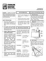
Rig unit using either belt or cable slings. Use spreader bars to protect the top of the unit when it
is lifted. See Figure 1, p. 10
On units with a total length of less than 104 inch (2642 mm), excluding evaporative cooler, two
holes are provided in the base rail on each side of the unit. Slide pipes beneath the unit through
these holes and attach rigging to pipes for lifting the unit.
On units with a total length of a 104 inch (2642 mm) or greater, excluding evaporative cooler,
lifting lugs attached to the base rail are provided. Attach rigging to lugs for lifting the unit. For
distance between lifting lugs and total unit lengths, refer to original Submittal Sheets supplied
specified for the unit. Also see Center of Gravity and Weights Sections in this manual.
GGeenneerraall SSaaffeettyy RReeqquuiirreemmeennttss

10
MUA-SVX003B-EN
Figure 1. Rigging
Combustion Air Considerations
The presence of chlorine vapors or other corrosive vapors in the combustion air supply for gas-fi
red heating equipment presents a potential corrosive hazard. Chlorine will, when exposed to
flame, precipitate from the compound (usually freon or degreaser vapors) and go into solution
with any condensation that is present in the heat exchanger or associated parts. The result is
hydrochloric acid which will readily attack all metals, including 300 grade stainless steel. Care
should be taken to separate these vapors from the combustion process. This may be done by
wise location of the unit with regard to exhausters or prevailing wind direction.
Location
WWAARRNNIINNGG
MMoouunnttiinngg IInntteeggrriittyy!!
FFaaiilluurree ttoo ffoollllooww iinnssttrruuccttiioonn bbeellooww ccoouulldd rreessuulltt iinn ddeeaatthh oorr sseerriioouuss iinnjjuurryy oorr ppoossssiibbllee
eeqquuiippmmeenntt oorr pprrooppeerrttyy--oonnllyy ddaammaaggee..
EEnnssuurree tthhee rrooooff ssttrruuccttuurree ssuuppppoorrttss aarree ssttrroonngg eennoouugghh ttoo ssuuppppoorrtt tthhee wweeiigghhtt ooff tthhee uunniitt
aanndd aannyy aacccceessssoorriieess..
Before placing rooftop unit in its permanent location, make certain that the roof is capable of
carrying the additional load of this equipment. Check the unit weight given at the end of this
manual.
GGeenneerraall SSaaffeettyy RReeqquuiirreemmeennttss

MUA-SVX003B-EN
11
Refer to Figure 2, p. 11 and Figure 3, p. 11 for required clearances to combustible material.
WWAARRNNIINNGG
PPrrooppeerr IInnssttaallllaattiioonn LLooccaattiioonn RReeqquuiirreedd!!
FFaaiilluurree ttoo ffoollllooww iinnssttrruuccttiioonnss bbeellooww ccoouulldd rreessuulltt iinn ddeeaatthh oorr sseerriioouuss iinnjjuurryy..
DDoo nnoott ppllaaccee uunniitt iinn aa llooccaattiioonn wwhheerree sseerrvviiccee ppeerrssoonnnneell ccaann nnoott ssaaffeellyy sseerrvviiccee tthhiiss
eeqquuiippmmeenntt ((ii..ee.. rrooooff eeddggee,, sskkyylliigghhttss,, eettcc..))..
NNoottee:: If your unit is equipped with through the base utilities and/or service convenience package
- refer to Submittal, review in entirety before mounting the unit.
Figure 2. Minimum Clearances to Combustible Material or Obstructions
Figure 3. Minimum Clearances to Combustible Material or Obstructions
NNoottee:: The unit is equipped with hinged access doors: allow 36 inches minimum for clearance (on
access side) to fully open door and lock in an open position.
GGeenneerraall SSaaffeettyy RReeqquuiirreemmeennttss

12
MUA-SVX003B-EN
Mounting/Locations
These units are suitable for installation on combustible flooring.
Single, double and triple duct furnace only models have base rails which can be mounted either
on solid planking or steel channels. All other units installed on field furnished supports must use
the recommended method shown in Mounting on Field Furnished Supports or equivalent.
Roof curb kits for rooftop units are shipped unassembled. Included with the roof curb kit are
insulated or uninsulated curb rails, bolts and screws needed for assembly, sealant, a roll of self-
adhering rubber gasketing, and installation instructions. Roof insulation, cant stripping, flashing,
roof felts, caulking, and nails must be furnished by the installer. See , separate roof curb
specifications.
If a variable frequency drive (VFD) has been ordered with the unit, consideration should be made
for the VFD operating temperature range: 14°F to 130°F. For temperatures below 14°F, VFD must
be factory-installed within the VFD Enclosure accessory (Model Digit 22, option 9), or field-
mounted indoors.
GGeenneerraall SSaaffeettyy RReeqquuiirreemmeennttss

MUA-SVX003B-EN
13
Installation
WWAARRNNIINNGG
HHaazzaarrddoouuss VVoollttaaggee!!
FFaaiilluurree ttoo ddiissccoonnnneecctt ppoowweerr bbeeffoorree sseerrvviicciinngg ccoouulldd rreessuulltt iinn ddeeaatthh oorr sseerriioouuss iinnjjuurryy..
DDiissccoonnnneecctt aallll eelleeccttrriicc ppoowweerr,, iinncclluuddiinngg rreemmoottee ddiissccoonnnneeccttss bbeeffoorree sseerrvviicciinngg.. FFoollllooww
pprrooppeerr lloocckkoouutt//ttaaggoouutt pprroocceedduurreess ttoo eennssuurree tthhee ppoowweerr ccaann nnoott bbee iinnaaddvveerrtteennttllyy
eenneerrggiizzeedd.. VVeerriiffyy tthhaatt nnoo ppoowweerr iiss pprreesseenntt wwiitthh aa vvoollttmmeetteerr..
Installation must conform with local building codes or in the absence of local codes with the
latest edition of the National Fuel Gas Code ANSI Z223.1 (N.F.P.A. No. 54) National Fuel Gas
Code.
A heat loss study and a complete layout of the system should be made first.
When locating the unit in its permanent location, make certain that the roof is capable of carrying
the additional load of the equipment. CChheecckk tthhee uunniitt nneett wweeiigghhttss sseeccttiioonn ooff tthhiiss mmaannuuaall.
Make certain that clearances are provided for service, minimum clearance to combustible
material and to venting cap. See Figure 2, p. 11 for this information.
Ducts connected to units which do not have either a blower section or a supply plenum must
have a removable access panel in the duct, which is connected to a duct furnace. The duct
openings shall be accessible when the unit is installed in service and shall be of such size that
smoke or reflected light may be observed inside the casing to indicate the presence of leaks in
the heating element. The covers for the panels shall be attached in such manner as to prevent
leaks. Ducts exposed to the outdoors must be insulated and sealed to prevent water from
entering either the unit or building through the duct.
If a single, double or triple duct furnace only unit is connected to a return air duct or any other
inlet air restriction, the appliance shall be installed on the positive pressure side of the air
circulating blower.
NNOOTTIICCEE
UUnniitt DDaammaaggee!!
FFaaiilluurree ttoo ffoollllooww iinnssttrruuccttiioonnss bbeellooww ccoouulldd rreessuulltt iinn uunniitt ddaammaaggee..
RReemmoovvee wwooooddeenn sshhiippppiinngg ssuuppppoorrtt ffrroomm bbeenneeaatthh bblloowweerr hhoouussiinngg ooff bblloowweerr SSeeccttiioonn..
Installation Clearances
WWAARRNNIINNGG
CCoommbbuussttiibbllee MMaatteerriiaallss!!
FFaaiilluurree ttoo mmaaiinnttaaiinn pprrooppeerr cclleeaarraannccee bbeettwweeeenn tthhee uunniitt aanndd ccoommbbuussttiibbllee mmaatteerriiaallss ccoouulldd
ccaauussee aa ffiirree wwhhiicchh ccoouulldd rreessuulltt iinn ddeeaatthh oorr sseerriioouuss iinnjjuurryy oorr pprrooppeerrttyy ddaammaaggee..
RReeffeerr ttoo uunniitt nnaammeeppllaattee aanndd iinnssttaallllaattiioonn iinnssttrruuccttiioonnss ffoorr pprrooppeerr cclleeaarraanncceess..
Minimum clearances to combustible material are shown on the unit data plate. It is important
that clearances be maintained for servicing the unit (refer to Submittal Insert for service
clearances), and that minimum clearances are provided from the unit (including vent cap, if
Natural Vent model) to combustible material. Clearances around the outside air hood (if unit is so
equipped) must be unobstructed. See Figure 2, p. 11.
Mounting on Field Furnished Supports
Single, double, triple duct furnace only models have base rails which are suitable for mounting
either directly on solid planking or steel channels. Never install the unit on a soft roof where the
rails could sink, reducing clearance between the bottom panel and the roof, or cause damage to
the roofing surface.

14
MUA-SVX003B-EN
All other models must use the following method or an equivalent when unit supports are field
furnished: Each section of the Rooftop unit must be supported, which includes supports located
at both ends. If the unit consists of a High CFM Blower section, a DX Coil, a Duct Furnace and a
Supply Plenum, five supports are required. See Figure 4, p. 14.
Figure 4. Mounting On Field-Furnished Supports
Mounting on Roof Curb
Assemble and install roof curb per Roof Curb Installation Instructions. See Figures Figure 5, p.
15, Figure 6, p. 21, Figure 7, p. 21, and Figure 8, p. 22 for roof opening sizes, distance between
openings and unit relationship to roof curb.
IInnssttaallllaattiioonn


16
MUA-SVX003B-EN
Table 1. GR Roof Curb Kit Dimensions
Rooftop
Arrange-
ment
Capaci-
ty
Trane P/N
F G H J
Q
R K M W B C
B
10/15
0134-0205-
01
29-5/8 8-1/8 71-1/8 67-3/8
69
76-3/8 1-1/2 1-1/2 26-7/16 30-3/16 35-7/16
(752) (206) (1,806) (1,711) (1,753) (1,940) (38) (38) (671) (767) (900)
B
20/25
0134-0205-
02
29-5/8 8-1/8 71-1/8 67-3/8
69
76-3/8 1-1/2 1-1/2 37-7/16 41-3/16 46-7/16
(752) (206) (1,806) (1,711) (1,753) (1,940) (38) (38) (951) (1,046) (1,179)
B
30/35
0134-0205-
03
29-5/8 8-1/8 71-1/8 67-3/8
69
76-3/8 1-1/2 1-1/2 48-7/16 52-3/16 57-7/16
(752) (206) (1,806) (1,711) (1,753) (1,940) (38) (38) (1,230) (1,325) (1,459)
B 40
0134-0205-
04
29-5/8 8-1/8 71-1/8 67-3/8
69
76-3/8 1-1/2 1-1/2 53-15/16 57-11/16 62-15/16
(752) (206) (1,806) (1,711) (1,753) (1,940) (38) (38) (1,370) (1,465) (1,599)
C
10/15
0134-0205-
05
29-5/8 34-1/8 97-1/8 93-3/8
95
102-3/8 1-1/2 1-1/2 26-7/16 30-3/16 35-7/16
(752) (867) (2,467) (2,371) (2,413) (2,600) (38) (38) (671) (767) (900)
C
20/25
0134-0205-
06
29-5/8 34-1/8 97-1/8 93-3/8
95
102-3/8 1-1/2 1-1/2 37-7/16 41-3/16 46-7/16
(752) (867) (2,467) (2,371) (2,413) (2,600) (38) (38) (951) (1,046) (1,179)
B 50
0134-0205-
06
29-5/8 34-1/8 97-1/8 93-3/8
95
102-3/8 1-1/2 1-1/2 37-7/16 41-3/16 46-7/16
(752) (867) (2,467) (2,371) (2,413) (2,600) (38) (38) (951) (1,046) (1,179)
C
30/35
0134-0205-
07
29-5/8 34-1/8 97-1/8 93-3/8
95
102-3/8 1-1/2 1-1/2 48-7/16 52-3/16 57-7/16
B
60/70
(752) (867) (2,467) (2,371) (2,413) (2,600) (38) (38) (1,230) (1,325) (1,459)
C 40
0134-0205-
08
29-5/8 34-1/8 97-1/8 93-3/8
95
102-3/8 1-1/2 1-1/2 53-15/16 57-11/16 62-15/16
B 80
(752) (867) (2,467) (2,371) (2,413) (2,600) (38) (38) (1,370) (1,465) (1,599)
C 50
0134-0205-
09
30-1/8
59 123
119-1/4 120-7/8 128-1/4 1-1/2 1-1/2 37-7/16 41-3/16 46-7/16
(765) (1,499) (3,124) (3,029) (3,070) (3,257) (38) (38) (951) (1,046) (1,179)
C
60/70
0134-0205-
10
30-1/8
59 123
119-1/4 120-7/8 128-1/4 1-1/2 1-1/2 48-7/16 52-3/16 57-7/16
(765) (1,499) (3,124) (3,029) (3,070) (3,257) (38) (38) (1,230) (1,325) (1,459)
C 80
0134-0205-
11
30-1/8
59 123
119-1/4 120-7/8 128-1/4 1-1/2 1-1/2 53-15/16 57-11/16 62-15/16
(765) (1,499) (3,124) (3,029) (3,070) (3,257) (38) (38) (1,370) (1,465) (1,599)
D
10/15
0134-0205-
12
29-5/8 8-1/8 71-1/8 67-3/8
69
76-3/8 1-1/2 1-1/2 26-7/16 30-3/16 35-7/16
(752) (206) (1,806) (1,711) (1,753) (1,940) (38) (38) (671) (767) (900)
IInnssttaallllaattiioonn

MUA-SVX003B-EN
17
Table 1. GR Roof Curb Kit Dimensions (continued)
Rooftop
Arrange-
ment
Capaci-
ty
Trane P/N
F G H J
Q
R K M W B C
D
20/25
0134-0205-
13
29-5/8 8-1/8 71-1/8 67-3/8
69
76-3/8 1-1/2 1-1/2 37-7/16 41-3/16 46-7/16
(752) (206) (1,806) (1,711) (1,753) (1,940) (38) (38) (951) (1,046) (1,179)
D
30/35
0134-0205-
14
29-5/8 8-1/8 71-1/8 67-3/8
69
76-3/8 1-1/2 1-1/2 48-7/16 52-3/16 57-7/16
(752) (206) (1,806) (1,711) (1,753) (1,940) (38) (38) (1,230) (1,325) (1,459)
D 40
0134-0205-
15
29-5/8 8-1/8 71-1/8 67-3/8
69
76-3/8 1-1/2 1-1/2 53-15/16 57-11/16 62-15/16
(752) (206) (1,806) (1,711) (1,753) (1,940) (38) (38) (1,370) (1,465) (1,599)
D 50
0134-0205-
16
29-5/8 34-1/8 97-1/8 93-3/8
95
102-3/8 1-1/2 1-1/2 37-7/16 41-3/16 46-7/16
E
20/25
(752) (867) (2,467) (2,371) (2,413) (2,600) (38) (38) (951) (1,046) (1,179)
D
60/70
0134-0205-
17
29-5/8 34-1/8 97-1/8 93-3/8
95
102-3/8 1-1/2 1-1/2 48-7/16 52-3/16 57-7/16
E
30/35
(752) (867) (2,467) (2,371) (2,413) (2,600) (38) (38) (1,230) (1,325) (1,459)
D 80
0134-0205-
18
29-5/8 34-1/8 97-1/8 93-3/8
95
102-3/8 1-1/2 1-1/2 53-15/16 57-11/16 62-15/16
E 40
(752) (867) (2,467) (2,371) (2,413) (2,600) (38) (38) (1,370) (1,465) (1,599)
E
10/15
0134-0205-
19
29-5/8 34-1/8 97-1/8 93-3/8
95
102-3/8 1-1/2 1-1/2 26-7/16 30-3/16 35-7/16
(752) (867) (2,467) (2,371) (2,413) (2,600) (38) (38) (671) (767) (900)
E 50
0134-0205-
20
30-1/8
59 123
119-1/4 120-7/8 128-1/4 1-1/2 1-1/2 37-7/16 41-3/16 46-7/16
(765) (1,499) (3,124) (3,029) (3,070) (3,257) (38) (38) (951) (1,046) (1,179)
E
60/70
0134-0205-
21
30-1/8
59 123
119-1/4 120-7/8 128-1/4 1-1/2 1-1/2 48-7/16 52-3/16 57-7/16
(765) (1,499) (3,124) (3,029) (3,070) (3,257) (38) (38) (1,230) (1,325) (1,459)
E 80
0134-0205-
22
30-1/8
59 123
119-1/4 120-7/8 128-1/4 1-1/2 1-1/2 53-15/16 57-11/16 62-15/16
(765) (1,499) (3,124) (3,029) (3,070) (3,257) (38) (38) (1,370) (1,465) (1,599)
G
20/25
0134-0205-
23
37-3/16 29-3/16 107-5/16 103-9/16 105-3/16 112-9/16 1-1/2 1-1/2 37-7/16 41-3/16 46-7/16
(944) (741) (2,726) (2,631) (2,672) (2,859) (38) (38) (951) (1,046) (1,179)
G
30/35
0134-0205-
24
37-3/16 29-3/16 107-5/16 103-9/16 105-3/16 112-9/16 1-1/2 1-1/2 48-7/16 52-3/16 57-7/16
(944) (741) (2,726) (2,631) (2,672) (2,859) (38) (38) (1,230) (1,325) (1,459)
G 40
0134-0205-
25
37-3/16 29-3/16 107-5/16 103-9/16 105-3/16 112-9/16 1-1/2 1-1/2 53-15/16 57-11/16 62-15/16
(944) (741) (2,726) (2,631) (2,672) (2,859) (38) (38) (1,370) (1,465) (1,599)
IInnssttaallllaattiioonn

18
MUA-SVX003B-EN
Table 1. GR Roof Curb Kit Dimensions (continued)
Rooftop
Arrange-
ment
Capaci-
ty
Trane P/N
F G H J
Q
R K M W B C
G 50
0134-0205-
26
37-1/8 55-1/4 133-1/4 129-1/2 131-1/8 138-1/2 1-1/2 1-1/2 37-7/16 41-3/16 46-7/16
J & K
20/25
(943) (1,403) (3,385) (3,289) (3,331) (3,518) (38) (38) (951) (1,046) (1,179)
G
60/70
0134-0205-
27
37-1/8 55-1/4 133-1/4 129-1/2 131-1/8 138-1/2 1-1/2 1-1/2 48-7/16 52-3/16 57-7/16
J & K
30/35
(943) (1,403) (3,385) (3,289) (3,331) (3,518) (38) (38) (1,230) (1,325) (1,459)
G 80
0134-0205-
28
37-1/8 55-1/4 133-1/4 129-1/2 131-1/8 138-1/2 1-1/2 1-1/2 53-15/16 57-11/16 62-15/16
(943) (1,403) (3,385) (3,289) (3,331) (3,518) (38) (38) (1,370) (1,465) (1,599)
G 12
0134-0205-
29
37-5/16 80-15/16 159-5/16 155-9/16 157-1/4 164-1/2 1-1/2 1-1/2 53-15/16 57-11/16 62-15/16
J & K 80
(948) (2,056) (4,046) (3,951) (3,994) (4,178) (38) (38) (1,370) (1,465) (1,599)
L 40
J & K 50
0134-0205-
30
37-5/16 80-15/16 159-5/16 155-9/16 157-1/4 164-1/2 1-1/2 1-1/2 37-7/16 41-3/16 46-7/16
L
20/25
(948) (2,056) (4,046) (3,951) (3,994) (4,178) (38) (38) (951) (1,046) (1,179)
J & K
60/70
0134-0205-
31
37-5/16 80-15/16 159-5/16 155-9/16 157-1/4 164-1/2 1-1/2 1-1/2 48-7/16 52-3/16 57-7/16
L
30/35
(948) (2,056) (4,046) (3,951) (3,994) (4,178) (38) (38) (1,230) (1,325) (1,459)
K
10/15
0134-0205-
32
37-1/8 55-1/4 133-1/4 129-1/2 131-1/8 138-1/2 1-1/2 1-1/2 26-7/16 30-3/16 35-7/16
(943) (1,403) (3,385) (3,289) (3,331) (3,518) (38) (38) (671) (767) (900)
J 12
0134-0205-
33
36-15/16
107-11/
16
185-5/16 181-9/16 183-1/4 190-1/2 1-1/2 1-1/2 53-15/16 57-11/16 62-15/16
L 80
(938) (2,735) (4,707) (4,612) (4,655) (4,839) (38) (38) (1,370) (1,465) (1,599)
L 50
0134-0205-
34
36-15/16
107-11/
16
185-5/16 181-9/16 183-1/4 190-1/2 1-1/2 1-1/2 37-7/16 41-3/16 46-7/16
(938) (2,735) (4,707) (4,612) (4,655) (4,839) (38) (38) (951) (1,046) (1,179)
L
30/70
0134-0205-
35
36-15/16
107-11/
16
185-5/16 181-9/16 183-1/4 190-1/2 1-1/2 1-1/2 48-7/16 52-3/16 57-7/16
(938) (2,735) (4,707) (4,612) (4,655) (4,839) (38) (38) (1,230) (1,325) (1,459)
L
10/15
0134-0205-
36
37-5/16 80-15/16 159-5/16 155-9/16 157-1/4 164-1/2 1-1/2 1-1/2 26-7/16 30-3/16 35-7/16
(948) (2,056) (4,046) (3,951) (3,994) (4,178) (38) (38) (671) (767) (900)
Note: Dimensions listed apply to both insulated and uninsulated roof curb types. Roof curb kit part numbers listed are the insulated roof curb type; contact customer service for
uninsulated part numbers.
IInnssttaallllaattiioonn

MUA-SVX003B-EN
19
Table 2. AH Roof Curb Kit Dimensions
Air Handler
Arrange-
ment
Capaci-
ty
Trane P/N
F G H J
Q
R K M W B C
B 20
0134-0214-
01
N/A N/A
45-1/4 41-1/2 43-1/8 50-1/2
N/A N/A
37-7/16 41-3/16 46-7/16
(1,149) (1,054) (1,095) (1,283) (951) (1,046) (1,179)
B 40
0134-0214-
02
N/A N/A
45-1/4 41-1/2 43-1/8 50-1/2
N/A N/A
53-15/16 57-11/16 62-15/16
(1,149) (1,054) (1,095) (1,283) (1,370) (1,465) (1,599)
C 20
0134-0214-
03
29-5/8 8-1/8 71-1/8 67-3/8
69
76-3/8 1-1/2 1-1/2 37-7/16 41-3/16 46-7/16
(752) (206) (1,806) (1,711) (1,753) (1,940) (38) (38) (951) (1,046) (1,179)
C 40
0134-0214-
04
29-5/8 8-1/8 71-1/8 67-3/8
69
76-3/8 1-1/2 1-1/2 53-15/16 57-11/16 62-15/16
(752) (206) (1,806) (1,711) (1,753) (1,940) (38) (38) (1,370) (1,465) (1,599)
D 20
0134-0214-
05
N/A N/A
45-1/4 41-1/2 43-1/8 50-1/2
N/A N/A
37-7/16 41-3/16 46-7/16
(1,149) (1,054) (1,095) (1,283) (951) (1,046) (1,179)
D 40
0134-0214-
06
N/A N/A
45-1/4 41-1/2 43-1/8 50-1/2
N/A N/A
53-15/16 57-11/16 62-15/16
(1,149) (1,054) (1,095) (1,283) (1,370) (1,465) (1,599)
E 20
0134-0214-
07
29-5/8 8-1/8 71-1/8 67-3/8
69
76-3/8 1-1/2 1-1/2 37-7/16 41-3/16 46-7/16
(752) (206) (1,806) (1,711) (1,753) (1,940) (38) (38) (951) (1,046) (1,179)
E 40
0134-0214-
08
29-5/8 8-1/8 71-1/8 67-3/8
69
76-3/8 1-1/2 1-1/2 53-15/16 57-11/16 62-15/16
(752) (206) (1,806) (1,711) (1,753) (1,940) (38) (38) (1,370) (1,465) (1,599)
G 20
0134-0214-
09
38-1/8
N/A
81-7/16 77-11/16 79-5/16 86-11/16 1-1/2
N/A
37-7/16 41-3/16 46-7/16
(968) (2,069) (1,973) (2,015) (2,202) (38) (951) (1,046) (1,179)
G 40
0134-0214-
10
38-1/8
N/A
81-7/16 77-11/16 79-5/16 86-11/16 1-1/2
N/A
53-15/16 57-11/16 62-15/16
(968) (2,069) (1,973) (2,015) (2,202) (38) (1,370) (1,465) (1,599)
J 20
0134-0214-
11
37-3/16 29-3/16 107-5/16 103-9/16 105-3/16 112-9/16 1-1/2 1-1/2 37-7/16 41-3/16 46-7/16
(944) (741) (2,726) (2,631) (2,672) (2,859) (38) (38) (951) (1,046) (1,179)
J 40
0134-0214-
12
37-3/16 29-3/16 107-5/16 103-9/16 105-3/16 112-9/16 1-1/2 1-1/2 53-15/16 57-11/16 62-15/16
(944) (741) (2,726) (2,631) (2,672) (2,859) (38) (38) (1,370) (1,465) (1,599)
K 20
0134-0214-
13
37-3/16 29-3/16 107-5/16 103-9/16 105-3/16 112-9/16 1-1/2 1-1/2 37-7/16 41-3/16 46-7/16
(944) (741) (2,726) (2,631) (2,672) (2,859) (38) (38) (951) (1,046) (1,179)
IInnssttaallllaattiioonn

20
MUA-SVX003B-EN
Table 2. AH Roof Curb Kit Dimensions (continued)
Air Handler
Arrange-
ment
Capaci-
ty
Trane P/N
F G H J
Q
R K M W B C
K 40
0134-0214-
14
37-3/16 29-3/16 107-5/16 103-9/16 105-3/16 112-9/16 1-1/2 1-1/2 53-15/16 57-11/16 62-15/16
(944) (741) (2,726) (2,631) (2,672) (2,859) (38) (38) (1,370) (1,465) (1,599)
L 20
0134-0214-
15
37-1/8 55-1/4 133-1/4 129-1/2 131-1/8 138-1/2 1-1/2 1-1/2 37-7/16 41-3/16 46-7/16
(943) (1,403) (3,385) (3,289) (3,331) (3,518) (38) (38) (951) (1,046) (1,179)
L 40
0134-0214-
16
37-1/8 55-1/4 133-1/4 129-1/2 131-1/8 138-1/2 1-1/2 1-1/2 53-15/16 57-11/16 62-15/16
(943) (1,403) (3,385) (3,289) (3,331) (3,518) (38) (38) (1,370) (1,465) (1,599)
IInnssttaallllaattiioonn
/