P.Audio XT-18P SUB User manual
- Category
- Musical Equipment
- Type
- User manual
This manual is also suitable for

P.AUDIO
XT SERIES MANUAL

1
READ ALL OF THE INSTRUCTIONS INCLUDED IN THIS MANUAL
The exclamation point within an equilateral triangle is intended to alert the user to the presence of important operation
and maintenance instructions.
The lightning flash with arrowhead symbol within an equilateral triangle is intended to alert the user to the presence of
un-insulated “dangerous voltage” within the products enclosure that may be of sufficient magnitude to constitute a risk
of electric shock to persons.
1. The following safety notices must be read and adhered to for safe operation of the XT range of products.
2. Copies of this manual should be retained by the system’s installer AND end-user.
3. This manual must be read and understood and ALL warnings must be followed.
4. Follow all instructions to insure optimal product performance.
5. The XT Active products are convection-cooled devices and require at least 6 inches (152 mm) of clearance behind the
enclosure to allow the heat sink to adequately cool the internal electronics.
6. DO NOT INSTALL NEAR ANY HEAT SOURCES!
7. Use ONLY the supplied AC Mains connector.
8. Protect the AC Mains power cord from being walked on or otherwise damaged and inspect for damaged connections and
damaged insulation.
9. The XT-15A and XT-18A Sub MAY NOT be suspended.
10. There are NO user-serviceable parts inside the enclosure. DO NOT REMOVE THE AMPLIFIER MODULE!
11. DO NOT use in outdoor/direct weather installations or applications. Use in INDOOR dry applications ONLY!

2
CONTENTS
FRONT COVER
1.
INTRODUCTION ........................................................................................................................................................................... 2
2. SPECIFICATIONS .......................................................................................................................................................................... 3
3. SETUP AND USE OF THE XT PRODUCTS ....................................................................................................................................... 5
3.1. AC MAINS CONNECTION .................................................................................................................................................... 5
3.2. AUDIO CONNECTIONS ....................................................................................................................................................... 6
4. REMOTE SOFTWARE – XT Series ................................................................................................................................................. 7
4.1. HARDWARE REQUIREMENTS ............................................................................................................................................. 7
4.2. COM CABLE ........................................................................................................................................................................ 7
4.3. ID ........................................................................................................................................................................................ 7
4.4. CONTROLLING THE XT SERIES SPEAKERS ........................................................................................................................... 8
4.5. PROTECTION ...................................................................................................................................................................... 9
5. APPLICATION AND TROUBLE SHOOTING TIPS ........................................................................................................................... 10
EQUALIZATION AND GAIN ......................................................................................................................................................... 10
6. PRODUCT SERVICE..................................................................................................................................................................... 11
1. INTRODUCTION
Thank you for purchasing one of the models in the XT range of products, and for your faith in us and our products. This product
will provide you many years of useful service with proper use and care. Please read this manual completely and become familiar
with the design and operation of this advanced active speaker system.
The XT Series of products is designed for both installation and portable, truly professional sound reinforcement systems. The XT
series of mid-hi cabinets are all passive, whilst the subwoofers are available in both active and passive versions. This manual will
concentrate on the active versions of the subwoofers.
The XT-15A and XT-18A Subwoofers feature a two-channel amplifier which delivers 500w (XT-15A) or 725w (XT-18A) to the
onboard transducer, and a further 500w (XT-15A) or 275w (XT-18A) to a Speakon connector on the rear panel, so it can be
connected a mid-hi cabinet from the XT Series, or the 3LINE-C enclosure.
The XT range of products are suitable for both portable and fixed installation indoor environments such as night clubs, pubs,
meeting halls and general live performance applications.

3
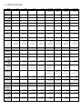
2. SPECIFICATIONS
Model
XT-8
XT-10
XT-12
XT-15
XT-15P SUB
XT-15A SUB
XT-18P SUB
XT-18A SUB
Type
Passive 2-Way
Passive 2-Way
Passive 2-Way
Passive 2-Way
Passive
Subwoofer
Active
Subwoofer
Passive
Subwoofer
Active
Subwoofer
Woofer Size
8"
10"
12"
15"
15"
15"
18"
18"
Woofer Voice
Coil
2"
2"
2.5"
3"
3"
3"
4"
4"
Compression
Driver Size
1"
1"
1"
1"
N/A
N/A
N/A
N/A
Throat Size
1"
1"
1.75"
1.75"
N/A
N/A
N/A
N/A
Cabinet
Construction
Plywood with
PU
Plywood with
PU
Plywood with
PU
Plywood with
PU
Plywood with
PU
Plywood with
PU
Plywood with
PU
Plywood with
PU
Handles
1
1
1
3
2
2
2
2
Top Hat
1 Top Hat
Receptacle
1 Top Hat
Receptacle
1 Top Hat
Receptacle
1 Top Hat
Receptacle
1 x M20
Pole Mount
1 x M20
Pole Mount
1 x M20
Pole Mount
1 x M20
Pole Mount
Weight
10kg/22lbs
13kg/28.7lbs
18.6kg/41lbs
26kg/57.3lbs
29kg/63.9lbs
31kg/68.3lbs
42kg/92.6lbs
44kg/97lbs
Dimensions
429 x 246 x
275mm/
16.9 x 9.7 x
10.8inches
485 x 290 x
331mm/
19.1 x 11.4 x
13inches
583 x 332 x
338.4mm/
23 x 13.1 x
13.3inches
583 x 332 x
338.4mm/
23 x 13.1 x
13.3inches
536 x 420 x
588mm/
21.1 x 16.5 x
23.2inches
536 x 420 x
588mm/
21.1 x 16.5 x
23.2inches
538 x 650 x
650mm/
21.2 x 25.6 x
25.6inches
538 x 650 x
650mm/
21.2 x 25.6 x
25.6inches
Acoustic
Specifications
Sensitivity
92dB
93dB
95dB
95dB
97dB
N/A
98dB
N/A
Frequency
Response -
3dB
80-18kHz
75-18kHz
70-18kHz
65-18kHz
45Hz-120Hz
45Hz-120Hz
40Hz-100Hz
40Hz-100Hz
Frequency
Response -
10dB
65 - 20kHz
60-20kHz
55-20kHz
50-20kHz
40Hz-150Hz
40Hz-150Hz
35Hz-80Hz
35Hz-80Hz
Power
Handling
200w
Continuous;
800w Peak
200w
Continuous;
800w Peak
250w
Continuous;
1000w Peak
400w
Continuous;
1600w Peak
500w
Continuous;
2000w Peak
N/A
600w
Continuous;
2400w Peak
N/A
Max SPL
Continuous
116dB
117dB
119dB
121dB
127dB
(Half Space
Environment)
127dB
(Half Space
Environment)
130dB
(Half Space
Environment)
128dB (Half
Space
Environment)
Max SPL Peak
122dB
123dB
125dB
127dB
133dB
133dB
136dB
134dB
Dispersion
90 x 65
90 x 65
90 x 40
90 x 40
Omni
directional
Omni
directional
Omni
directional
Omni
directional
Electrical
Specifications
Impedance
8 Ohms
8 Ohms
8 Ohms
8 Ohms
8 Ohms
N/A
8 Ohms
N/A
Input
Connectors
Speakon
Connector
Speakon
Connector
Speakon
Connector
Speakon
Connector
Speakon
Connector
Line XLR
Speakon
Connector
Line XLR
Link
Connectors
Speakon
Connector
Speakon
Connector
Speakon
Connector
Speakon
Connector
Speakon
Connector
Line XLR
Speakon
Connector
Line XLR

4
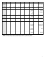
Output
Connectors
None
None
None
None
None
Hi Pass
Speakon
Output
None
Hi Pass
Speakon Output
Controls
N/A
N/A
N/A
N/A
N/A
Rotating
Knob
N/A
Rotating Knob
Preset
Control
N/A
N/A
N/A
N/A
N/A
Preset
Selection
(8 Presets);
Connection
to XT
Software
N/A
Preset
Selection
(8 Presets);
Connection to
XT Software
Power
Output
N/A
N/A
N/A
N/A
N/A
500w @ 1%
THD to 2
Channels
N/A
500w @ 1% THD
to 2 Channels
Amplifier
Type
N/A
N/A
N/A
N/A
N/A
Class D with
Switch Mode
Power Supply
N/A
Class D with
Switch Mode
Power Supply
Protection
N/A
N/A
N/A
N/A
N/A
Turn On
Delay; Short
Circuit
Protection;
DC Voltage
Protection;
Peak Voltage
Limiter; Over
Temperature
Protection;
RMS Limiter
N/A
Turn On Delay;
Short Circuit
Protection; DC
Voltage
Protection; Peak
Voltage Limiter;
Over
Temperature
Protection; RMS
Limiter
Indicators
N/A
N/A
N/A
N/A
N/A
Power LED;
Clip LED;
Signal LED
N/A
Power LED;
Clip LED;
Signal LED
* NOTE: Max Acoustic Output is based on smoothed system response, not peak driver response.
P.Audio is continually looking to improve products, so specifications are subject to change without notice.

5
3. SETUP AND USE OF THE XT PRODUCTS
3.1. AC MAINS CONNECTION
NOTE: The powered models in the XT series use an automatic switching power supply. ONLY the 3 pin mains power
lead supplied with the unit may be used. DO NOT SUBSTITUTE AC MAINS POWER CONNECTION LEADS.
Prior to connecting the AC mains cable, ensure that the AC mains switch is in the OFF position. The XT range of products will
operate on AC mains voltages of 115 volts to 230 volts. The required AC mains frequency is between 45 Hz and 65 Hz. The
acceptable voltage range is 85VAC-265VAC. The amplifier’s switch mode power supply (SMPS) will automatically adjust to the
mains voltage present.
The powered XT enclosures use a standard IEC type connector system. To mate the AC mains cable with the AC mains connector
on the amplifier, simply align the plug with the panel’s connector, and push into the connector. Always support the enclosure with
one hand whilst performing this operation. The AC mains connector is shown above. To disconnect the cable end of the AC mains
connector, pull back on the plug to remove. Do not pull on the cable.
NOTE: ALWAYS turn off the AC mains power BEFORE attempting to disconnect the AC mains cable from the XT amplifier
module!

6
NOTE: DO NOT CONNECT THE AC MAINS END OF THE AC MAINS CABLE IN AN AREA THAT IS WET OR SUBJECT TO
CONDENSATION OR DAMP CONDITIONS!
Once the AC mains cable is securely connected to both the amplifier and AC mains supply, the amplifier may be turned on. It is
good practice to make certain that the audio levels on the mixer’s output (or other source output) are reduced or muted prior to
applying power. The pilot light is located on the rear panel.
NOTE: If the pilot light does not illuminate within 30 seconds the unit may be in a FAULT CONDITION. If this occurs, the
unit should be returned to P.Audio for evaluation.
THERE ARE NO USER-SERVICABLE PARTS INSIDE. DO NOT REMOVE THE AMPLIFIER MODULE! (See the section below
“Replacement of Components” for more detailed information).
3.2. AUDIO
CONNECTIONS
The XT amplifiers include both male and female XLR-type connectors, and speakon connectors. Any standard XLR-type cable end
connectors may be used.
The image below illustrates the inputs found on the amplifier plate. Line Input and Line Output (THRU) are shown. All the necessary
EQ is provided in the on board pre amp. A line level input of voltage 0.775v will drive the on board amplifiers to full power.
The XT input section also allows for “paralleling” multiple powered enclosures together. This function is achieved by using the Line
Output XLR-type connector located next to the input XLR-type connector on the amplifier module.
The output level can be
controlled using the level control knob, or using remote software (see section REMOTE SOFTWARE).
The preset EQ may be adjusted to match one of the cabinets in the XT series (presets 1-4), the 3LINE-C enclosure (Preset 5), user
presets adjusted with the remote control software (presets 6,7) or pink noise (preset 8). The pink noise preset is useful as a locator
in case the knob is lost, and also for system set up.

7
4. REMOTE SOFTWARE – XT SERIES
The remote control software enables the user to adjust EQ, delay, polarity, noise gates and other aspects of the XT series
enclosures performance. Once the unit is connected to the computer, any changes made on the computer will become active,
but will NOT be saved onto the amplifier, until the preset is stored onto the XT series amplifier.
4.1. HARDWARE REQUIREMENTS
Essential:
Windows computer running windows XP or newer operating system. At this time, compatibility with windows 8.1 is not
guaranteed.
Spare hard drive space of 50MB
Recommended:
RAM
2GB
Operating System
Windows 7
Processor
Dual core 2gHz or higher
4.2. COM CABLE
The COM cable is an accessory, available from P.Audio, which allows the user to take
control of the XT series amplifiers from any windows based PC. Upon connecting
the COM cable and opening XT software, a dialog screen will appear checking
options for connecting to the device in question. To ensure communication occurs
on the right COM cable, this must be selected from the drop down list.
For linking between amplifiers, standard CAT5 type cabling can be used.
To connect the COM cable to the XT series amplifiers, simply connect the USB plug
to the windows computer, and plug the other end into the socket on any available
XT series amplifier. Ensure to align the plug correctly and do not exert too much
force onto the USB plug.
4.3. ID
Once the required amplifiers are all linked together, the software can be started.
To start the software, click start All Programs XT SERIES XT SERIES
Application.
Once the COM cable is chosen, the software needs to know which units to
communicate with. ID for XT series amplifiers as set by the factory range from 1-
32, although the user to is free to change this as they see fit with the ‘configure ID
Device’ utility. The software can communicate with a maximum of 32 units at
once.
Once all is set up, press OK and the software will launch.

8
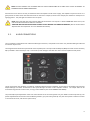
4.4. CONTROLLING THE XT SERIES SPEAKERS
Once the software is up and running, all connected speakers will be seen in the ID list to the left hand side of the screen. All
parameters available to the user will be available by double clicking the device required to monitor, and the parameters screen
will be displayed.
Across the top of the parameters window, there are several options available to the user:
Load – Allows loading of a preset file from a storage location such as the computer hard drive.
Save – Allows saving of the current parameters to a file in a storage location such as the computer hard drive.
Store – Allows storing of the current parameters to a preset location on the amplifier. Locations are provided to the user to enable
this, and avoid writing over any factory presets. Once a preset is overwritten, the original preset file must be used to recover the
data.
Recall – Loads a preset from the amplifier memory, remotely. This allows presets to be changed on units in inaccessible locations.
However, once the COM cable is removed, the unit will revert back to the preset as indicated by the knob on the unit itself.
Name Device – This allows the user to change the name for each device, and this is stored in the amplifier memory. The name
will also be changed in the ID list to allow for easy identification.
From the parameters page, the following parameters can be adjusted:
Input Source – Allows the user to select between a noise source and the analog input. The noise source is especially useful when
tuning the system to a particular room, or for fault finding.
Noise Generator – Provides level control and noise type when noise generator is selected as the input.
Phase – Polarity switching is allowed with the option of 0 or 180 degrees.
Delay – Delay can be specified in both time and distance. Delays for low and high, and system delay are available.

9
DLF – DLF is a set of filters tuned specifically to make recorded music sound more dynamic at low levels. In the ‘music’ presets on
the amplifier, this option is turned on.
High Pass Filter – All of the cabinets already have a high pass filter programmed in, but an extra high pass filter is provided to the
user for crossover, or extra subsonic filtering.
5 Band Parametric EQ – Q factors up to 10 are available to give the user complete control over the sound of their system.
Mute – Controls for system mute, and low and high mute are available to the user.
4.5. PROTECTION
In installation, or when the operator is away from the desk, it is understandable that protection will be desired to ensure other
users do not get unwanted access. If the LOCK button is pressed, a password prompt will be shown.
To block use to all features of the software (only signal monitoring will be seen), please use the password: dspamp
For advanced users only (not recommended): to gain access to the individual processing for the transducer components, please
use password: outamp
For very advanced users only (not recommended): to gain access to master compressor/limiter settings, please use password:
limamp
For standard use, presets 1-4 and 8 are locked by the factory. Should the user wish to store any additional presets, it is possible
to do so in slots 5,6,7. This is done by editing the preset as required, and pressing the store button. Attempting to store the preset
in any other slot will result in an error message.

10
5. APPLICATION AND TROUBLE SHOOTING TIPS
The XT Series makes up components of a high-quality professional sound reinforcement system designed for use in both indoor,
and dry outdoor applications. Some basic precautions will insure long-term reliability.
EQUALIZATION AND GAIN
The XT-15A SUB and 18A SUB have all the required equalization and gain functions included in the digital signal processing circuits.
Both the equalization and gain functions have been optimized for flat frequency response and maximized system dynamics.
If distorted sound is heard the gain and EQ settings on the outboard mixer and any other external equipment should be carefully
checked to ensure that the input section of the XT enclosure is not overloaded.
If additional equalization is required, care should be taken to avoid excessive EQ in any frequency band, but particularly at low
frequencies. Excessive equalization can produce “band selective” clipping and distortion. All EQ boost levels should be monitored
if system distortion is present.
PROBLEM: Distorted sound
When input levels to the XT amplifiers exceed 0.775 V RMS for line level inputs it is possible to produce system clipping or
overdrive. It is still possible to “overdrive” the input section of the enclosure. If distorted sound is present the following steps
should be taken:
1. Verify that the mixer’s output is not clipping or overloaded. If the output metering section of the mixing console is
continuously in the “red” then the output level should be reduced. (occasional “red” indications are usually fine and are
dependent on the mixing console’s output capability).
2. Verify that excessive equalization is not present anywhere in the signal chain.
3. Verify that AC mains levels are within the required range.
Voltage measurements on the AC Mains should be performed by a licensed electrician or individual trained in making
high-voltage measurements.
PROBLEM: No sound from active units
1. Verify that the amplifier pilot light is on.
2. Verify that there is AC Mains voltage on the AC Mains input to the amplifier.
NOTE: NOT DO ATTEMPT TO REPLACE THE FUSE. THERE ARE NO USER SERVICABLE PARTS INSIDE THE XT SERIES
AMPLIFIERS.

11
6. PRODUCT SERVICE
The XT amplifier module MUST be serviced by a company authorized by P. Audio.
Replacement of Components
REPLACEMENT OF COMPONENTS MUST BE PERFORMED BY A QUALIFIED TECHNICIAN OR ONE KNOWLEDGABLE IN THE
REPLACEMENT OF TRANSDUCER COMPONENTS!
DO NOT ATTEMPT ANY REPAIRS UNLESS THE XT SERIES AMPLIFIER HAS BEEN DISCONNECTED FROM THE AC MAINS
SOURCE!
In the event of woofer failure, the woofer may be accessed by removing the front grille and then removing the drive
unit. This should be done by a qualified technician or contractor. There is no need to remove the amplifier panel in the
event of a woofer failure.
USE EXTREME CARE WHEN HANDLING THE XT AMPLIFIER MODULES. THE COMPONENTS ARE FRAGILE AND THE MODULE MUST
NOT BE SET DOWN ON THE COMPONENT SIDE OR DAMAGE WILL OCCUR!
NOTE: The powered models in the XT series feature an internal fuse to protect the power amplifier. THE INTERNAL FUSE
IS NOT USER REPLACABLE. UNDER NO CIRCUMSTANCES SHOULD THE AMPLIFIER PANEL BE REMOVED FROM THE
CABINET.
Care should be exercised when disconnecting the amplifier module from both the woofer. Be sure to observe the wiring polarity
of the woofer.
Thank you once again for purchasing this P.Audio product. P.Audio is a manufacturer of a complete range of Loudspeaker systems,
individual components and accessories. For more information regarding any of P.Audio’s products or advice on how to set up and
use this product, please do not hesitate to use the contact details on the following page to contact us.
Please scan this QR code for quick access
to the P.Audio website.
P Audio System Co., Ltd. 19/4 Moo 2 T.Bangkratuk
A.Samparn , Nakornpathom. 73210,Thailand
Tel: +66-2-441 6600 (Auto 30 Lines)
Fax: +66-2-441 6699
e-mail: info@paudiothailand.com
www.paudiothailand.com
P.Audio U.S.
div. of One Systems, Inc.
2000 Glen Echo Rd., STE 103
Nashville, TN 37215
Tel: +1-615-823-1655
Fax: +1-615-261-1429
Email: info@onesystems.com
www.paudious.com and www.onesystems.com
-
 1
1
-
 2
2
-
 3
3
-
 4
4
-
 5
5
-
 6
6
-
 7
7
-
 8
8
-
 9
9
-
 10
10
-
 11
11
-
 12
12


P.Audio XT-18P SUB User manual
- Category
- Musical Equipment
- Type
- User manual
- This manual is also suitable for
Ask a question and I''ll find the answer in the document
Finding information in a document is now easier with AI
Other documents
-
Tannoy VTH TOP HAT Quick start guide
-
 W Audio SM12A User manual
-
Martin Audio Blackline X115 User Guides
-
Turbosound NuQ SERIES User manual
-
Gigabyte Portable Speaker GP-S5500 User manual
-
Jamo 42086051 Datasheet
-
Tascam CDR510 User manual
-
-
-
Samson Power Amplifiers User manual
