Hikoki C10FSH Handling Instructions Manual
- Category
- Power tools
- Type
- Handling Instructions Manual
This manual is also suitable for

Slide Compound Miter Saw
◷᫇⪿ᠧ# ㊯㙗⧿ᠧ✣
C 10FSH
•
C 10FSB
Handling instructions
⺒ຳ# ⇎ᬯ⇆
Readthroughcarefullyandunderstandtheseinstructionsbeforeuse.
ᶢ#⇎ᬯ⇆ᨦ#⠺⇢㠲#⠧ඊ#ᅞ❓⟮#⋃⩪㘆#ᕎ#⣆㔲⟮#⅖❓㘂⎗⎆⛎1

1
1
2
34
56
7
8
2
1
2
N
8
4
6
7
G
0
C
H
F
E
M
3
5
9
A
B
D
L
K
J
I
P
Q
R
O
S
T
V
W
X
Y
]
[
Z
\
W
^
1
]
P
1
L
1
8
U
C
D
a
K
b
c
4
7
d
E
D
U
2
n
§
00Table_C10FSH_WE 10/19/11, 8:591

2
910
11 12
13
14 15
e
f
g
h
i
j
a
k
f
h
i
l
m
n
o
p
q
r
s
t
u
a
v
O
w
C
w
x
\
Do not show in
the laser line.
(laser beam)
LASER CLASS Po<3mW,
C6=3, (lambda)=654nm,
Time basis 0.25s
DIN EN 60825-1:2001-11
C417607
LASER RADIATION
00Table_C10FSH_WE 10/19/11, 8:592

3
16 17
18 19
20
21
22
23
J
z
I
G
F
†
M
£
ç
†
M
B
¢
ç
S
{
e
~
}
|
{
p
q
r
s
t
v
}~
å
Z
Y
8
X
y
e
43
6 mm
17 mm
00Table_C10FSH_WE 10/19/11, 8:593

4
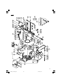
English 한국어
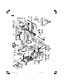
1
Handle
핸들
2
Lever (A)
레버(A)
3
Motor Head
모터 헤드
4
Gear Case
기어 케이스
5
Motor
모터
6
Dust Bag
분진 주머니
7
Hinge
힌지
8
Holder (A)
홀더(A)
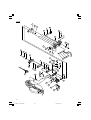
9
Sub Cover
하위 커버
0
Indicator (For right bevel scale)
표시등(우측 베벨 눈금용)
!
Laser Marker (Only C10FSH)
레이저 마커(C10FSH만 해당)
@
Saw Blade
톱날
#
Vise Assembly
바이스 어셈블리
$
Fence (B)
펜스(B)
%
Sub Fence
서브 펜스
^
Lever
레버
&
Side Handle
사이드 핸들
*
Turntable
턴테이블
(
Table Insert
테이블 인서트
)
Indicator (For miter scale)
표시등(미터 눈금용)
q
Fence (A)
펜스(A)
w
Lower Guard
하부 보호대
e
Washer (D)
와셔(D)
r
Spindle Cover
스핀들 커버
t
Switch (For laser marker) (Only C10FSH)
스위치(레이저 마커용)(C10FSH만 해당)
y
Trigger Switch
작동 스위치
u
5 mm Screw
5 mm 나사
i
Nameplate
명판
o
Spindle Lock
스핀들 잠금장치
p
Belt Cover
벨트 커버
a
Guard
보호대
s
Base
베이스
d
Holder
홀더
f
Fixing Pin
고정 핀
g
Clamp Lever
클램프 레버
h
Indicator (For left bevel scale)
표시등(좌측 베벨 눈금용)
j
Slide Securing Knob
슬라이드 고정 노브
k
Adjuster (For laser marker)(Only C10FSH)
조절장치(레이저 마커용)(C10FSH만 해당)
l
Locking Pin
잠금 핀
;
6 mm Bolt
6 mm 볼트

5
English 한국어
z
Workpiece
작업물
x
8 mm Hexagon Socket Set Screw
8 mm 육각 소켓 세트 스크루
c
8 mm Depth Adjustment Bolt
8 mm 깊이 조정 볼트
v
8 mm Wing Nut
8 mm 윙 너트
b
6 mm Knob Bolt (Optional accessory)
6 mm 노브 볼트(옵션 부속품)
n
Holder (Optional accessory)
홀더(옵션 부속품)
m
Steel Square
곱자
,
6 mm Wing Nut (Optional accessory)
6 mm 윙 너트(옵션 부속품)
.
Height Adjustment Bolt 6 mm (Optional accessory)
높이 조정 볼트 6 mm (옵션 부속품)
/
Base Surface
베이스 표면
¡
Stopper (Optional accessory)
스토퍼(옵션 부속품)
™
6 mm Knob Bolt (Optional accessory)
6 mm 노브 볼트(옵션 부속품)
£
Sub Fence (A)
하위 펜스(A)
¢
6 mm Bolt
6 mm 볼트
∞
Screw Holder
나사 홀더
§
6 mm Knob Bolt
6 mm 노브 볼트
¶
V-Groove
V-홈
•
Groove
홈
ª
Fence
펜스
º
6 mm Knob Bolt
6 mm 노브 볼트
⁄
Vise Plate
바이스 플레이트
¤
Knob
노브
‹
Laser line
레이저 라인
›
Groove
홈
fi
Bevel Scale
베벨 눈금
fl
Miter Scale
미터 눈금
‡
Crown molding Vise Ass’y (Optional accessory)
크라운 몰딩 바이스 어셈블리(옵션 부속품)
°
6 mm Wing Nut (Optional accessory)
6 mm 윙 너트(옵션 부속품)
·
Crown molding Stopper (L) (Optional accessory)
크라운 몰딩 스토퍼(L)(옵션 부속품)
‚
Crown molding Stopper (R) (Optional accessory)
크라운 몰딩 스토퍼(R)(옵션 부속품)
Œ
Crown molding
크라운 몰딩
„
10 mm Box Wrench
10 mm 박스 렌치
´
Bolt
볼트
‰
Washer (D) and Collar (B)
와셔(D)와 칼라(B)
ˇ
Wear limit line
마모 한계선
Á
6 mm Knob Bolt
6 m
m 노브 볼트

6
English
GENERAL OPERATIONAL PRECAUTIONS
WARNING! When using electric tools, basic safety
precautions should always be followed to reduce the risk
of fire, electric shock and personal injury, including the
following.
Read all these instructions before operating this product
and save these instructions.
For safe operations:
1. Keep work area clean. Cluttered areas and benches
invite injuries.
2. Consider work area environment. Do not expose
power tools to rain. Do not use power tools in damp
or wet locations. Keep work area well lit.
Do not use power tools where there is risk to cause
fire or explosion.
3. Guard against electric shock. Avoid body contact
with earthed or grounded surfaces (e.g. pipes,
radiators, ranges, refrigerators).
4. Keep children and infirm persons away. Do not let
visitors touch the tool or extension cord. All visitors
should be kept away from work area.
5. Store idle tools. When not in use, tools should be
stored in a dry, high or locked up place, out of reach
of children and infirm persons.
6. Do not force the tool. It will do the job better and
safer at the rate for which it was intended.
7. Use the right tool. Do not force small tools or
attachments to do the job of a heavy duty tool. Do
not use tools for purposes not intended; for example,
do not use circular saw to cut tree limbs or logs.
8. Dress properly. Do not wear loose clothing or
jewelry, they can be caught in moving parts. Rubber
gloves and non-skid footwear are recommended
when working outdoors. Wear protecting hair
covering to contain long hair.
9. Use eye protection. Also use face or dust mask if
the cutting operation is dusty.
10. Connect dust extraction equipment.
Cutting operation by this slide compound miter saw
may produce considerable amount of dust from
extraction duct on fixed guard.
(Dust material: Wood or Aluminium)
If devices are provided for the connection of dust
extraction and collection facilities ensure these are
connected and properly used.
11. Do not abuse the cord. Never carry the tool by the
cord or yank it to disconnect it from the receptacle.
Keep the cord away from heat, oil and sharp edges.
12. Secure work. Use clamps or a vise to hold the work.
It is safer than using your hand and it frees both
hands to operate tool.
13. Do not overreach. Keep proper footing and balance
at all times.
14. Maintain tools with care. Keep cutting tools sharp
and clean for better and safer performance. Follow
instructions for lubrication and changing
accessories. Inspect tool cords periodically and if
damaged, have it repaired by authorized service
center. Inspect extension cords periodically and
replace, if damaged. Keep handles dry, clean, and
free from oil and grease.
15. Disconnect tools. When not in use, before servicing,
and when changing accessories such as blades, bits
and cutters.
16. Remove adjusting keys and wrenches. Form the
habit of checking to see that keys and adjusting
wrenches are removed from the tool before turning
it on.
17. Avoid unintentional starting. Do not carry a plugged-
in tool with a finger on the switch. Ensure switch is
off when plugging in.
18. Use outdoor extension leads. When tool is used
outdoors, use only extension cords intended for
outdoor use.
19. Stay alert. Watch what you are doing. Use common
sense. Do not operate tool when you are tired.
20. Check damaged parts. Before further use of the tool,
a guard or other part that is damaged should be
carefully checked to determine that it will operate
properly and perform its intended function. Check
for alignment of moving parts, free running of
moving parts, breakage of parts, mounting and any
other conditions that may affect its operation. A
guard or other part that is damaged should be
properly repaired or replaced by an authorized
service center unless otherwise indicated in this
handling instructions. Have defective switches
replaced by an authorized service center. Do not use
the tool if the switch does not turn it on and off.
21. Warning
The use of any accessory or attachment, other than
those recommended in this handling instructions,
may present a risk of personal injury.
22. Have your tool repaired by a qualified person.
This electric tool is in accordance with the relevant
safety requirements. Repairs should only be carried
out by qualified persons using original spare parts.
Otherwise this may result in considerable danger
to the user.
PRECAUTIONS ON USING SLIDE COMPOUND
MITER SAW
1. Keep the floor area around the machine level. Well
maintained and free of loose materials e.g. chips
and cut-offs.
2. Provide adequate general or localized lighting.
3. Do not use power tools for applications other than
those specified in the handling instructions.
4. Repairing must be done only by authorized service
facility. Manufacturer is not responsible for any
damages and injuries due to the repair by the
unauthorized persons as well as the mishandling of
the tool.
5. To ensure the designed operational integrity of
power tools, do not remove installed covers or
screws.
6. Do not touch movable parts or accessories unless
the power source has been disconnected.
7. Use your tool at lower input than specified on the
nameplate; otherwise, the finish may be spoiled and
working efficiency reduced due to motor overload.
8. Do not wipe plastic parts with solvent. Solvents such
as gasoline, thinner, benzine, carbon tetrachloride,
alcohol, may damage and crack plastic parts. Do not
wipe them with such solvent. Clean plastic parts with
a soft cloth lightly dampened with soapy water.
9. Use only original HiKOKI replacement parts.
10. This tool should only be disassembled for
replacement of carbon brushes.
11. The exploded assembly drawing on this handling
instructions should be used only for authorized
service facility.
12. Never cut ferrous metals or masonry.
13. Adequate general or localized lighting is provided.
Stock and finished workpieces are located close to
the operators normal working position.
14. Wear suitable personal protective equipment when
necessary, this could include:
Hearing protection to reduce the risk of induced
hearing loss.
Eye protection to reduce the risk of injuring an eye.
Respiratory protection to reduce the risk of
inhalation of harmful dust.
01Eng_C10FSH_WE 10/19/11, 8:596

7
English
Gloves for handling saw blades (saw blades shall
be carried in a holder wherever practicable) and
rough material.
15. The operator is adequately trained in the use,
adjustment and operation of the machine.
16. Refrain from removing any cut-offs or other parts
of the workpiece from the cutting area whilst the
machine is running and the saw head is not in the
rest position.
17. Never use the slide compound miter saw with its
lower guard locked in the open position.
18. Ensure that the lower guard moves smoothly.
19. Do not use the saw without guards in position, in
good working order and properly maintained.
20. Use correctly sharpened saw blades. Observe the
maximum speed marked on the saw blade.
21. Do not use saw blades which are damaged or
deformed.
22. Do not use saw blades manufactured from high
speed steel.
23. Use only saw blades recommended by HiKOKI.
Use of saw blade comply with EN847-1.
24. The saw blades should be from 235 mm to 262 mm
external diameter ranges.
25. Select the correct saw blade for the material to be
cut.
26. Never operate the slide compound miter saw with
the saw blade turned upward or to the side.
27. Ensure that the workpiece is free of foreign matter
such as nails.
28. Replace the table insert when worn.
29. Do not use the saw to cut other than aluminium,
wood or similar materials.
30. Do not use the saw to cut other materials than those
recommended by the manufacturer.
31. Blade replacement procedure, including the method
for repositioning and a warning that this must be
carried out correctly.
32. Connect the slide compound miter saw to a dust
collecting device when sawing wood.
33. Take care when slotting.
34. When transporting or carrying the tool, do not grasp
the holder. Grasp the handle instead of the holder.
35. Start cutting only after motor revolution reaches
maximum speed.
36. Promptly cut OFF the switch when abnormality
observed.
37. Shut off power and wait for saw blade to stop before
servicing or adjusting tool.
38. During a miter or bevel cut the blade should not be
lifted until it has stopped rotation completely.
39. During slide cutting operation, the saw must be
pushed and slided away from the operator.
40. Take all the possibility of residual risks in cutting
operation into your consideration, such as the laser
radiation to your eyes, the inadvertent access to
moving parts on slide mechanical parts on machine
and so on.
SPECIFICATIONS
* Be sure to check the nameplate on product as it is subject to change by areas.
0° 85 mm × 312 mm
Miter 45° 85 mm × 218 mm
Left 45° 55 mm × 305 mm
Bevel
Right 45° 30 mm × 305 mm
Bevel (Left) 45° + Miter 45°
55 mm × 218 mm
Compound Bevel (Right) 45° + Miter (Left) 31° 30 mm × 260 mm
Bevel (Right) 45° + Miter (Right) 45° 30 mm × 218 mm
Saw Blade Dimensions (oD × iD × Thickness) 262 mm × 25.4 mm × 2.3 mm
Miter Cutting Angle Right 0° – 57°, Left 0° – 45°
Bevel Cutting Angle Right and Left 0° – 45°
Compound Cutting Angle
Bevel (Left) 0° – 45°
Miter (Right and Left) 0° – 45°
Bevel (Right) 0° – 45°
Voltage (by areas)* (220 V)
Power Input* 1090 W
No-Load Speed 3800 /min
Machine Dimensions (Width × Depth × Height) 545 mm × 1050 mm × 615 mm
Weight (Net) 19.5 kg
Maximum output Po<3 mW Class Laser Product
(Iambda) 654 nm
Laser medium Laser Diode
Max. Cutting
Capacity
Height × Width
Laser Marker
(Only Model C10FSH)
01Eng_C10FSH_WE 4/25/12, 11:487

8
English
STANDARD ACCESSORIES
(1) 262 mm TCT Saw blade (mounted on tool) .............. 1
(2) Dust bag ...................................................................... 1
(3) 10 mm Box wrench .................................................... 1
(4) Vise Assembly ............................................................ 1
(5) Holder .......................................................................... 1
(6) Sub Fence (A) ............................................................. 1
Standard accessories are subject to change without notice.
OPTIONAL ACCESSORIES (SOLD SEPARATELY)
(1) Extension Holder and Stopper
(2) Saw blade 262 mm TCT Saw blade (Total teeth: 60)
(3) Crown molding Vise Ass'y (Include Crown molding
Stopper (L))
(4) Crown molding Stopper (L)
(5) Crown molding Stopper (R)
Optional accessories are subject to change without notice.
APPLICATION
Cutting various types of aluminium sash and wood.
UNPACKING
䡬 Carefully unpack the power tool and all related items
(standard accessories).
䡬 Check carefully to make certain all related items
(standard accessories) are present.
PRIOR TO OPERATION
1. Power source
Ensure that the power source to be utilized conforms
to the power requirements specified on the product
nameplate.
2. Power switch
Ensure that the power switch is in the OFF position. If
the plug is connected to a receptacle while the trigger
switch is in the ON position, the power tool will start
operating immediately, inviting serious accident.
3. Extention cord
When the work area is removed from the power
source, use an extension cord of sufficient thickness
and rated capacity. The extension cord should be kept
as short as practicable.
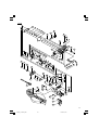
4. When the power tool is prepared for shipping, its
main parts are secured by a locking pin
Move the handle slightly so that the locking pin can
be disengaged.
During transport, lock the locking pin into the gear
case (Fig. 4).
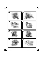
5. Attach the dust bag to the main unit (Fig. 1)
6. Installation
Ensure that the machine is always fixed to bench.
Attach the power tool to a level, horizontal work bench.
Select 8 mm diameter bolts suitable in length for the
thickness of the work bench.
Bolt length should be at least 25 mm plus the thickness
of the work bench.
For example, use 8 mm × 65 mm bolts for a 25 mm
thick work bench.
ADJUSTING THE POWER TOOL PRIOR TO USE
CAUTION
Make all necessary adjustments before inserting the
plug in the power source.
1. Check to see that the lower guard operates smoothly
CAUTION
䡬 This slide compound miter saw is equipped with a
saw head lock as safety device.
䡬 To lower the saw head to cut, the lock must be released
by pressing the lever (A) with your thumb.
(1) When you push down the handle while pushing the
lever (A), check that the lower guard revolves
smoothly (Fig. 5).
(2) Next, check that the lower guard returns to the original
position when the handle is raised.
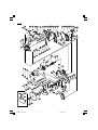
2. Checking the saw blade lower limit position (Fig. 7)
Check that the saw blade can be lowered 10 mm to
11 mm below the table insert.
If necessary, adjust as follows:
(1) Loosen the 8 mm wing nut.
(2) Insert your 6 mm hexagon bar wrench from behind
of the tool and turn the 8 mm hexagon socket set
screw to the left (counterclockwise) viewed from
behind of the tool.
(3) Turn the 8 mm depth adjustment bolt, change the
height where the bolt head and the gear case contacts,
and adjust the lower limit position of the saw blade.
One turn of the 8 mm depth adjustment bolt changes
the lower limit position of the saw blade by about 8
mm, and this information can be used as a rough
guide.
(4) Turn the 8 mm hexagon socket set screw to the right
(clockwise) as viewed from behind of the tool, and let
it softly contact the tip of the 8 mm depth adjustment
bolt.
CAUTION
Adjust the lower limit position so that the saw blade
will not cut the turntable or complete cutting cannot
be done.
PRACTICAL APPLICATIONS
CAUTION
䡬 It is dangerous to remove or install the workpiece
while the saw blade is turning.
䡬 When sawing, clean off the shavings from the
turntable.
䡬 If the shavings accumulate too much, the saw blade
from the cutting material will be exposed. Never
subject your hand or anything else to go near the
exposed blade.
1. Tightly secure the material by vise assembly to be
cut so that it does not move during cutting
2. Switch operation
Pulling the trigger turns the switch on. Releasing the
trigger turns the switch off.
3. Base holder adjustment (Fig. 3)
Loosen the 6 mm bolt with the supplied 10 mm box
wrench. Adjust the base holder until its bottom surface
contacts the bench or the floor surface.
4. Cutting a groove on the guard
Holder (A) has a guard (see Fig. 6) into which a groove
must be cut. Loosen the 6 mm knob bolt to retract the
guard slightly.
01Eng_C10FSH_WE 4/25/12, 11:488

9
English
After placing a suitable wooden piece to sit on the
fence and the table surfaces, fix it with the vise. After
the switch has been turned on and the saw blade has
reached maximum speed, slowly lower the handle to
cut a groove on the guard.
CAUTION
Do not cut the groove too quickly; otherwise the guard
might become damaged.
5. Adjusting the guard (Fig. 6)
(1) In the case of cutting at a right angle or bevel cutting:
Loosen the 6 mm knob bolt, bring the guard lightly in
contact with the materials to be cut and secure. Align
the ink line with the saw blade groove on the guard
and begin operations.
(2) In the case of miter cutting or miter cutting plus bevel
cutting:
Loosen the 6 mm knob bolt, move the guard to the
back, making sure that it is not sticking out from the
fence surface.
6. Using the Vise Assembly (Standard accessory) (Fig. 12)
The vise assembly can be mounted on either the left
fence (Fence (B)), or the right fence (Fence(A)), and
can be raised or lowered according to the height of
the workpiece. To raise or lower the vise assembly,
first loosen the 6 mm knob bolt. The vise shaft has
three locking grooves into which the tip of the 6 mm
wing bolt is designed to fit in order to lock the screw
holder in the desired position. To ensure that the tip
of the 6 mm wing bolt is properly aligned with the
desired locking groove on the vise shaft, simply align
the upper surface of the fence to either of three V-
grooves on the vise shaft surface or to the lower
surface of the screw holder. Therefore, the vise
assembly can be attached in either of three positions
to ensure proper height adjustment.
After adjusting the height, firmly tighten the 6 mm
wing bolt; then turn the upper knob, as necessary, to
securely attach the workpiece in position.
WARNING
Always firmly clamp or vise to secure the workpiece
to the fence; otherwise the workpiece might be thrust
from the table and cause bodily harm.
CAUTION
Always confirm that the motor head does not contact
the vise assembly when it is lowered for cutting. If there
is any danger that it may do so, loosen the 6 mm wing
bolt and move the vise assembly to a position where it
will not contact the saw blade.
7. Positioning the table insert (Fig. 1)
Table inserts are installed on the turntable. When
shipping the tool from the factory, the table inserts
are so fixed that the saw blade does not contact them.
The burr of the bottom surface of the workpiece is
remarkably reduced, if the table insert is fixed so that
the gap between the side surface of the table insert
and the saw blade will be minimum. Before using the
tool, eliminate this gap in accordance with the
following procedure.
Loosen the three 6 mm machine screws, then secure
the left side table insert and temporarily tighten the 6
mm machine screws of both ends. Then fix a
workpiece (about 200 mm wide) with the vise
assembly and cut it off. After aligning the cutting
surface with the edge of the table insert, securely
tighten the 6 mm machine screws of both ends.
Remove the workpiece and securely tighten the 6 mm
center machine screw. Adjust the right hand table
insert in the same way.
CAUTION
After adjusting the table insert for right angle cutting,
the table insert will be cut to some extent if it is used
for bevel angle cutting.
When bevel cutting operation is required, adjust the
table insert for bevel angle cutting.
8. Confirmation for use of sub fence
This power tool is equipped with a sub fence. In the
case of direct angle cutting and right bevel angle
cutting, use the sub fence. Then, you can do Left bevel
angle cutting, Right bevel angle cutting and Direct
angle cutting and realize stable cutting of the material
with a wide back face.
WARNING
In the case of left bevel cutting, turn the sub fence
counterclockwise (Fig. 8). Unless it is turned
counterclockwise, the main body or saw blade may
contact the sub fence, resulting in an injury.
9. Confirmation for use of sub fence (A) (Fig. 11)
In the case of direct angle cutting and angle cutting,
use the sub fence (A). The sub fence (A) can be
installed on the right side of the guide fence. Insert
the rods of the sub fence (A) into the holes in the guide
fence. Tighten the 6 mm bolt which come with the
sub fence (A) to secure the sub fence (A). Then, you
can realize stable cutting of the material with a wide
back face.
WARNING
In the case of right bevel cutting, remove the sub fence
(A). Supposing it is not able to remove it, it will contact
the blade or some part of the tool, causing in serious
injury to operator.
10. Using an ink line
(1) Right angle cutting
Loosen the 6 mm knob bolt and contact the tip of the
guard with the workpiece.
Aligning the ink line on the workpiece with the groove
of the guard, the workpiece is cut on the ink line.
(2) Miter cutting and compound cutting (Miter cutting +
bevel cutting)
Upon lowering the motor section, the lower guard is
raised and the saw blade appears.
Align the ink line with the saw blade.
CAUTION
In some arrangements when the turntable is rotated,
the guard projects from the fence surface. Loosen the
6 mm knob bolt and push the guard to the retracted
position. Never lift the lower guard while the saw
blade is rotating. When cutting at an angle of 35° to
the right or more, please slide the guard to the rear.
The guard and sub-fence will not only make contact
and adversely affect cutting accuracy, this could also
result in damage to the guard.
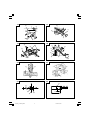
11. Position adjustment of laser line (Only Model C10FSH)
Ink lining can be easily made on this tool to the laser
marker. A switch lights up the laser marker (Fig. 14).
The laser line is adjusted to the width of the saw blade
at the time of factory shipment. Adjust the positions
of the saw blade and the laser line taking the following
steps to suit the use of your choice.
01Eng_C10FSH_WE 10/19/11, 8:599

10
English
(1) Light up the laser marker and make a groove of about 5
mm deep on the workpiece that is about 20 mm in height
and 150 mm in width. Hold the grooved workpiece by
vise as it is and do not move it. For grooving work, refer
to “22. Groove cutting procedures”.
(2) Then, turn the adjuster and shift the laser line. (If you
turn the adjuster clockwise, the laser line will shift to
the right and if you turn it counterclockwise, the laser
line will shift to the left.) When you work with the ink
line aligned with the left side of the saw blade, align
the laser line with the left end of the groove (Fig. 15).
When you align it with the right side of the saw blade,
align the laser line with the right side of the groove.
(3) After adjusting the position of the laser line, draw a
right-angle ink line on the workpiece and align the
ink line with the laser line. When aligning the ink line,
slide the workpiece little by little and secure it by vise
at a position where the laser line overlaps with the
ink line. Work on the grooving again and check the
position of the laser line. If you wish to change the
laser line’s position, make adjustments again
following the steps from (1) to (3).
WARNING
䡬 Make sure before plugging the power plug into the
receptacle that the main body and the laser marker
are turned off.
䡬 Exercise utmost caution in handling a switch trigger
for the position adjustment of the laser line, as the
power plug is plugged into the receptacle during
operation.
If the switch trigger is pulled inadvertently, the saw
blade can rotate and result in unexpected accidents.
䡬 Do not remove the laser marker to be used for other
purposes.
CAUTION (Fig. 13)
䡬 Laser radiation - Do not stare into beam.
䡬 Laser radiation on work table. Do not stare into beam.
If your eye is exposed directly to the laser beam, it
can be hurt.
䡬 Do not dismantle it.
䡬 Do not give strong impact to the laser marker (main
body of tool); otherwise, the position of a laser line
can go out of order, resulting in the damage of the
laser marker as well as a shortened service life.
䡬 Keep the laser marker lit only during a cutting
operation. Prolonged lighting of the laser marker can
result in a shortened service life.
䡬 Use of controls or adjustments or performance of
procedures other than those specified herein may
result in hazardous radiation exposure.
NOTE
䡬 In outdoor or near-the-window operations, it may
become dificult to observe the laser line due to the
sunlight. Under such circumstances, move to a place
that is not directly under the sunlight and engage in
the operation.
䡬 Do not tug on the cord behind the motor head or hook
your finger, wood and the like around it; otherwise,
the cord may come off and the laser marker may not
be lit up.
12. Cutting operation
(1) After turning on the switch and checking that the saw
blade is rotating at maximum speed, slowly push
down the handle while holding down the lever (A)
and bring the saw blade in the vicinity of the material
to be cut.
(2) Once the saw blade contacts the workpiece, push the
handle down gradually to cut into the workpiece.
(3) After cutting the workpiece to the desired depth, turn
the power tool OFF and let the saw blade stop
completely before raising the handle from the
workpiece to return it to the full retract position.
CAUTION
䡬 For maximum dimensions for cutting, refer to
“SPECIFICATIONS” table.
䡬 Increased pressure on the handle will not increase the
cutting speed. On the contrary, too much pressure
may result in overload of the motor and/or decreased
cutting efficiency.
䡬 Confirm that the trigger switch is turned OFF and the
power plug has been removed from the receptacle
whenever the tool is not in use.
䡬 Always turn the power off and let the saw blade stop
completely before raising the handle from the
workpiece. If the handle is raised while the saw blade
is still rotating, the cut-off piece may become jammed
against the saw blade causing fragments to scatter
about dangerously.
䡬 Every time one cutting of deep-cutting operation is
finished, turn the switch off, and check that the saw
blade has stopped. Then raise the handle, and return
it to the full retract position.
䡬 Be absolutely sure to remove the cut material from
the top of the turntable, and then proceed to the next
step.
13. Cutting narrow workpieces (Press cutting)
Slide the hinge down to holder (A), then tighten the
slide securing knob (see Fig. 2). Lower the handle to
cut the workpiece. Using the power tool this way will
permit cutting of workpieces of up to 85 mm square.
14. Cutting wide workpieces (Slide cutting)
Loosen the slide securing knob (see Fig. 2), grip the
handle and slide the saw blade forward. Then press
down on the handle and slide the saw blade back to
cut the workpiece. This facilitates cutting of
workpieces of up to 312 mm in width.
WARNING
Never put your hand on the side handle during the
cutting operation because the saw blade comes close
to the side handle when the motor head is lowered.
15. Miter cutting procedures
(1) Loosen the side handle and pull up the lever for angle
stoppers. Then, adjust the turntable until the indicator
aligns with desired setting on the miter scale (Fig. 17).
(2) Re-tighten the side handle to secure the turntable in
the desired position.
(3) The miter scale indicates both the cutting angle on
the angle scale and the gradient on the grade scale.
(4) The gradient, which is the ratio of the height to the
base of the triangular section to be removed, may be
used for setting the miter scale instead of the cutting
angle, if desired.
(5) Therefore, to cut a workpiece at a grade of 2/10, set
the indicator to position.
NOTE
䡬 Positive stops are provided at the right and left of the
0° center setting, at 15°, 22.5°, 30° and 45° settings.
Check that the miter scale and the tip of the indicator
are properly aligned.
䡬 Operation of the saw with the miter scale and indicator
out of alignment, or with the side handle not properly
tightened, will result in poor cutting precision.
01Eng_C10FSH_WE 10/19/11, 8:5910

11
English
16. Bevel cutting procedures
CAUTION
䡬 Ensure that the clamp lever is securely fixed when
beveling.
䡬 Please do this if the length of the material being cut
off is more than 25 mm long. Sometimes cutting
cannot be accomplished because the saw blade will
catch on the inside of the lower guard.
(1) Loosen the clamp lever and bevel the saw blade to
the left or to the right. When tilting the motor head to
the right pull the fixing pin towards the rear.
The clamp lever adopts a latchet system. When
contacting the work bench and the main body, pull
the clamp lever in the direction of the arrow mark as
illustrated in Fig. 16, and change the direction of the
clamp lever.
(2) Adjust the bevel angle to the desired setting while
watching the bevel angle scale and indicator, then
secure the clamp lever.
WARNING
When the workpiece is secured on the left or right
side of the blade, the short cut-off portion will come
to rest on the right or left side of the saw blade. Always
turn the power off and let the saw blade stop
completely before raising the handle from the
workpiece.
If the handle is raised while the saw blade is still
rotating, the cut-off piece may become jammed
against the saw blade causing fragments to scatter
about dangerously.
17. Compound cutting procedures
Compound cutting can be performed by following the
instructions in 14 and 15 above. For maximum
dimensions for compound cutting, refer to
“SPECIFICATIONS” table.
CAUTION
Always secure the workpiece with the right or left hand
and cut it by sliding the round portion of the saw
backwards with the left hand.
It is very dangerous to rotate the turntable to the left
during compound cutting because the saw blade may
come into contact with the hand that is securing the
workpiece.
In case of compound cutting (angle + bevel) by left
bevel, turn the sub-fence counterclockwise, and
engage in the cutting operation.
18. Cutting long materials
When cutting long materials, use an auxiliary platform
which is the same height as the holder (optional
accessory) and base of the special auxiliary
equipment.
Capacity: wooden material (W × H × L)
300 mm × 45 mm × 1300 mm, or
180 mm × 25 mm × 2000 mm
19. Installing the holders … (Optional accessory)
The holders help keep longer workpieces stable and
in place during the cutting operation.
(1) As indicated in Fig. 9, use a steel square for aligning
the upper edge of the holders with the base surface.
Loosen the 6 mm wing nut. Turn a height adjustment
bolt 6 mm, and adjust the height of the holder.
(2) After adjustment, firmly tighten the wing nut and
fasten the holder with the 6 mm knob bolt (optional
accessory). If the length of Height Adjustment Bolt 6
mm is insufficient, spread a thin plate beneath. Make
sure the end of Height Adjustment Bolt 6 mm does
not protrude from the holder.
CAUTION
䡬 When transporting or carrying the tool, do not grasp
the holder.
䡬 There is the danger of the holder slipping out of the
base. Grasp the handle instead of the holder.
20. Stopper for precision cutting … (Stopper and holder
are optional accessory)
The stopper facilitates continuous precision cutting
in lengths of 280 mm to 450 mm.
To install the stopper, attach it to the holder with the
6 mm knob bolt as shown in Fig. 10.
21. Confirmation for use Crown molding vise, Crown
molding Stopper (L) and (R) (Optional accessory)
(1) Crown molding Stopper (L) and (R) (optional
accessories) allow easier cuts of crown molding
without tilting the saw blade. lnstall them in the base
both-sides side to be shown in Fig. 18. After inserting
tighten the 6 mm knob bolts to secure the Crown
molding Stoppers.
(2) The crown molding vise (B) (Optional accessory) can
be mounted on either the left fence (Fence (B)) or the
right fence (Fence (A)). lt can unite with the slope of
the crown molding and vice can be pressed down.
Then turn the upper knob, as necessary, to securely
attach the crown molding in position. To raise or lower
the vise assembly, first loosen the 6 mm knob bolt.
As shown in Fig. 19 the vise shaft has three locking
grooves into which the tip of the 6 mm wing bolt is
designed to fit in order to lock the screw holder in the
desired position.
To ensure that the tip of the 6 mm wing bolt is properly
aligned with the desired locking groove on the vise
shaft, simply align the upper surface of the fence to
either of three v-grooves on the vise shaft surface or
to the lower surface of the screw holder.
Therefore, the vise assembly can be attached in either
of three positions to ensure proper height adjustment.
After adjusting the height, firmly tighten the 6 mm
wing bolt; then turn the upper knob, as necessary, to
securely attach the the crown molding in position (See
Fig 19).
Position crown molding with its WALL CONTACT
EDGE against the guide fence and its CEILING
CONTACT EDGE against the Crown molding Stoppers
as shown in Fig. 19. Adjust the Crown molding
Stoppers according to the size of the crown molding.
Tighten the 6 mm wing bolt to secure the Crown
molding Stoppers. Refer to the lower table for the
miter angle.
Use the sub fence (A) to secure the crown molding
more firmly (See Fig. 11).
WARNING
Always firmly clamp or vise to secure the crown
molding to the fence; otherwise the crown molding
might be thrust from the table and cause bodily harm.
Do not bevel cutting. The main body or saw blade
may contact the sub fence, resulting in an injury.
22. Groove cutting procedures
Grooves in the workpiece can be cut by adjusting the
8 mm depth adjustment bolt (Fig. 7).
(1) Loosen the 8 mm wing nut and turn the 8 mm depth
adjustment bolt by hand.
(2) Adjust to the desired cutting depth by setting the
distance between the saw blade and the surface of
the base.
(3) The 8 mm wing nut must be properly tightened after
the adjustment has been completed.
01Eng_C10FSH_WE 10/19/11, 8:5911

12
English
NOTE
When cutting a single groove at either end of the
workpiece, remove the unneeded portion with a
chisel.
MOUNTING AND DISMOUNTING SAW BLADE
WARNING
To prevent an accident or personal injury, always turn
off the trigger switch and disconnect the power plug
from the receptacle before removing or installing a
blade.
1. Mounting the saw blade (Fig. 20, Fig. 21 and Fig. 22)
(1) Use the accessory 10 mm box wrench to loosen the 6 mm
bolt fastening the spindle cover and then rotate the
spindle cover.
(2) Press in spindle lock and loosen bolt with 10 mm box
wrench.
Since the bolt is left-hand threaded, loosen by turning
it to the right.
NOTE
If the spindle lock cannot be easily pressed in to lock
the spindle, turn the bolt with 10 mm box wrench
while applying pressure on the spindle lock.
The saw blade spindle is locked when the spindle lock
is pressed inward.
(3) Remove the bolt and washer (D).
(4) Lift the lower guard and mount the saw blade.
WARNING
When mounting the saw blade, confirm that the
rotation indicator mark on the saw blade and the
rotation direction of the gear case are properly
matched.
(5) Thoroughly clean washer (D) and the bolt, and install
them onto the saw blade spindle.
(6) Press in the spindle lock and tighten the bolt by turning
it to the left by 10 mm box wrench.
(7) Rotate the spindle cover unitl hook in spindle cover is
in the original position. Then tighten the 6mm bolt.
CAUTION
䡬 Confirm that the spindle lock has returned to the
retract position after installing or removing the saw
blade.
䡬 Tighten the bolt so it does not come loose during
operation.
䡬 Confirm that the bolt has been properly tightened
before the power tool is started.
䡬 Confirm that the lower guard has closed position.
2. Dismounting the saw blade
Dismount the saw blade by reversing the mounting
procedures described in paragraph 1 above.
The saw blade can easily be removed after lifting the
lower guard.
CAUTION
Never attempt to install saw blades except
235 mm – 262 mm in diameter.
OVERLOAD PROTECTIVE DEVICE FOR POLY-V-BELT
The power of the motor is transmitted to the saw blade
by a Poly-V-Belt. When the Poly-V-Belt becomes
overloaded, this protective device reduce the input
voltage and the motor is going to stall as result.
However if the over-load is relieved by operator, the
machine recover the running gradually as before in short
time.
In this case turn the switch off immediately and raise the
handle to its initial position. Then turn the switch on and
after running the tool for 20 seconds without a load for
cooling of the motor. Then start the cutting operation.
The Poly-V-Belt or the motor will be damaged if the
overload protective device turns off frequently.
CAUTION
When the overload protective device stops the motor,
the motor will start by turning the switch on after
turning it off. When turning the switch on, make sure
that the saw blade is not halfway in the material.
MAINTENANCE AND INSPECTION
WARNING
To avoid an accident or personal injury, always
confirm the trigger switch is turned OFF and that the
power plug has been disconnected from the
receptacle before performing any maintenance or
inspection of this tool.
Report to qualified person as soon as possible, if you
discover the fault of machine including guards or
blade saw.
1. Inspecting the saw blade
Since use of a dull saw blade will degrade efficiency
and cause possible motor malfunction, sharpen or
replace the saw blade as soon as abrasion is noted.
To avoid excessive noise exposure, use the saw blades
designed to reduce the emitted noise and maintain
saw blade and machine.
2. Inspecting the mounting screws
Regularly inspect all mounting screws and ensure that
they are properly tightened. Should any of the screws
be loose, re-tighten them immediately. Failure to do
so could result in serious hazard.
3. Inspecting the carbon brushes (Fig. 13)
The motor employs carbon brushes which are
consumable parts. Since an excessively worn carbon
brush can result in motor trouble, replace the carbon
brushes with new ones having the same carbon brush
No. shown in the figure when it becomes worn to or
near the “wear limit”. In addition, always keep carbon
brushes clean and ensure that they slide freely within
the brush holders.
4. Replacing a carbon brushes
Disassemble the brush cap with a slotted-head
screwdriver. The carbon brushes can then be easily
removed.
5. Maintenance of the motor
The motor unit winding is the very “heart” of the
power tool. Exercise due care to ensure the winding
does not become damaged and/or wet with oil or
water.
6. Replacement of Poly-V-Belt
The power of the motor is transmitted to the saw blade
by a Poly-V-Belt. When the Poly-V-Belt is broken or
damaged, remove the belt cover by loosening the two
5 mm screws (see Fig. 2) and replace the damaged
one with the new one.
When connecting the belt on pulleys, first connect 2
or 3 teeth of Poly-V-Belt to the grooves of the pulley
(A) and pulley (B). Then turning the pulley (A) and
pulley (B), connect all 10 teeth of the belt to the pulleys.
01Eng_C10FSH_WE 4/25/12, 11:5112

13
English
7. Lubrication
Lubricate the following sliding surfaces once a month
to keep the power tool in good operating condition
for a long time.
Use of machine oil is recommended.
Oil supply points:
* Rotary portion of hinge
* Rotary portion of sub fence
* Rotary portion of vise assembly
8. Cleaning
Periodically remove chips and other waste material
from the surface of the power tool with a damp, soapy
cloth. To avoid a malfunction of the motor, protect it
from contact with oil or water.
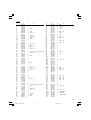
9. Service parts list
A:Item No.
B:Code No.
C:No. Used
D:Remarks
CAUTION
Repair, modification and inspection of HiKOKI Power
T
ools must be carried out by a HiKOKI Authorized
Service Center.
Especially laser device should be maintained by the
authorised agent by laser manufacturer.
Always assign the repair of laser device to HiKOKI
Authorised Service Center.
This Parts List will be helpful if presented with the
tool to the HiKOKI Authorized Service Center when
requesting repair or other maintenance.
In the operation and maintenance of power tools, the
safety regulations and standards prescribed in each
country must be observed.
MODIFICATIONS
H
iKOKI Power Tools are constantly being improved
and modified to incorporate the latest technological
advancements.
Accordingly, some parts (i.e. code numbers and/or
design) may be changed without prior notice.
NOTE
Due to HiKOKI’s continuing program of research and
development the specifications herein are subject to
change without prior notice.
01Eng_C10FSH_WE 10/19/11, 8:5913

14
⫇ὣ#⮻⫝̸#ⱇ⪣⏷㢸
ဈါ$#⢮ᒃ#㋞⟮#⅖❓㘊#ᗶ/#㘗Ⅻ#ᎎ⟶⟮#㒖㘒㘆#ᶢ⢫#◲⢮#
⦦⠂⅖㘗⟮#⦪⋂㘂⚖#㛾⡖/# ⢮#Ჹ#Ⅻ㘞⠂#➮㚂⟮#⦮⚖☦#
㘓፲ᎎ1
⠞# ⣆㔲⟮# ⠻ᒃ㘂# ⢮♺# ⠞# ⩪⼒⟮# ᭒ᓺ# ⠧⟪# 㝮# ᵮᑮᤆ#
ᶞඪ㘂⎗⎆⛎1
◲⢮㘆#⤚⠻⟮#➮㘆#⦦⠂⅖㘗=
41# ⠻♯#ඟಮ⟮#ⵗ൚㘂ശ#㘂⎗⎆⛎1#⠻♯#ඟಮඦ#⠻♯Ꭺಪ#
⢿ᑲᓂ♞#⠲⩪#◴⟮#൧❚#Ⅻ㘞ಪ#⟊᳆ᓓ፲ᎎ1
51# ⠻♯# ඟಮ# 㜂൧⟮# ඊᣎ㘂⎗⎆⛎1# ⢮ᒃ# ㋞⟮# ἁ᯦♺#
ሢ⹆⎆ㅎ⩪# ᩲ⎗⎆⛎1#⢮ᒃ# ㋞⟮# ⣀ചᅂ# ⍟㘆#⡏∶♺⇆#
⅖❓㘂⩪#ᩲ⎗⎆⛎1#⠻♯#ඟಮ⠂#⤚ᬯ#Ⅻㆆᨦ#☻㛢㘂ശ#
⟊⩪㘂⎗⎆⛎1
# 㛾⡖#ᚺጾ#㒗᳆⠞#᳆ↇ㘊#➮㚂⠞#⠲ጾ#⡏∶♺⇆ጾ# ⢮ᒃ#
㋞⟮#⅖❓㘂⩪#ᩲ⎗⎆⛎1
61# ⢮⟮# ᳓⩪㘂⎗⎆⛎1# ♞⍎ᓂചᅂ# ⢻⩪ᓆ# 㔆ᬞ+㎶⠞㖮/#
ᠦᖾ♺⠞㇚/#ᢲ⠢⩪/#ᅳ⡏ඊ#ᖛ,♺#⎊ⵞಪ#⢻ⶳ㘂⩪#◴ശ#
㘂⎗⎆⛎1
71# ♞ᩚ⠞⛪#ሢ☧⠺⠂#∺⠞#Ꭹ⩪#◴ശ#㘂⎗⎆⛎1#᳓ᯢ⠺ಪ#
ඟถ# ᚺጾ# ⚚⡏# ⿾ᖆᨦ# ᩶⩪⩪# ᭥㘂ശ# 㘂⎗⎆⛎1# ᭒ᖊ#
᳓ᯢ⠺ጾ#⠻♯#ඟಮ♺⇆#ᙒ♞⣢#⠲♞☦#㘓፲ᎎ1
81# ⅖❓㘂⩪#◴ጾ#ඟถጾ#ᶞඪ㘂⎗⎆⛎1#⅖❓㘂⩪#◴⟮#ᗶ/#
ඟถጾ# ഞ⤚㘂ചᅂ# ሼചᅂ# ⠺᯦⊊ᤆ# ⡊ຢᬚ# ♞ᩚ⠞⛪#
ሢ☧⠺⠂#∺⠞#Ꭹ⩪#◴ጾ#⡏∶♺#ᶞඪ㘞☦#㘓፲ᎎ1
91# ඟถ♺#㡂⟮#ಪ㘂⩪#ᩲ⎗⎆⛎1#ඟถጾ#⩪⢿ᓆ#∷ᑮ♺⇆#
⠻♯⟮##⡂##◲⢮㘂ശ#⋂㘳㘓፲ᎎ1
:1# ⛖Ჾᨢ#ඟถᨦ#⅖❓㘂⎗⎆⛎1#⠻⟪#ඟถ#ᚺጾ#⠻♯⡏⼂ᨦ#
⅖❓㘂⚖#Ꭺ㚿#ඟถ⠂#⠻♯⟮#♟⩪ᤆ#⋂㘳㘂⩪#ᩲ⎗⎆⛎1#
ඟถᨦ#⩪⢿ᓂ⩪#◴⟪#᭓⢫♺#⅖❓㘂⩪#ᩲ⎗⎆⛎1#⚲ᨦ#
ᖎ♞# ❺㚿# ㉛⟮# ⅖❓㘂⚖# ᅂᯱಪ⩪# ᚺጾ# ㉟ᅂᯞᨦ#
⠺᨞⩪#ᩲ⎗⎆⛎1
;1# ⛖Ჾᨢ#ᶟ⡏⟮#ⳓ❓㘂⎗⎆⛎1#㙺㘆#ᶟ⡏#ᚺጾ#⡏⎊ถᨦ#
ⳓ❓㘂⩪# ᩲ⎗⎆⛎1# ❪⩫⠞ጾ# Ḫ㔲♺# ἒᣎᖎ♞ಲ# ⋂#
⠲⍟፲ᎎ1#☦✢#⠻♯#⎆#ඊᯞ⡏ඦ#Ტხᢦ#᳓⩪#⎊᳆⟮#
ⳓ❓㘊#ഭ⟮#ึ⡏㘓፲ᎎ1# ᩖ⼞ᠧ⠞#ᬞ#ᶞ㛢# ᭒⠺ᨦ#
ⳓ❓㘂⚖#ᩖ⼞ᠧ⟮#᭒⠺#◲♺#ᇍ⟦⎗⎆⛎1
<1# ᶞ◲൧⟮# ⳓ❓㘂⎗⎆⛎1# ⢲᎒# ⠻♯# ⎆# Ḯ⩮⠞# ᳆ↇ㘊#
൧❚#◲ᬞ#ᩲ⍎ㄖ#ᚺጾ#᳓⩮#ᩲ⍎ㄖᨦ#ⳓ❓㘂⎗⎆⛎1
431#Ḯ⩮#⸾⹆#⡏Ữᨦ#⚚൚㘂⎗⎆⛎1
# ⠞#⍖ᠦ⠞ᖆ#⾞㎶❞ᖆ#ᩲ⠞㇚#㉛⟦ᤆ#⢲᎒#⠻♯⟮#㘂ᬞ#
ඊ⢿#ᶞ㛢Ꭺ⠂#⸾⹆#㍢♺⇆#᩸⟪#☻⠂#Ḯ⩮⠞#ↇ⇛ᓊ#
⋂#⠲⍟፲ᎎ1
# +Ḯ⩮#᯦⩲=#᭓⡖#ᚺጾ#◶ᦒᲢጮ,
# Ḯ⩮#⸾⹆#Ჹ#⋂ച#⇎Ữ#⚚൚⟮#➮㘆#⡏⼂ಪ#⣆ඟᓊ#൧❚/#
⠞ᢖ㘆# ⡏⼂ᖎ⠞# ⚚൚ᓂ♞# ⠲ඊ# ⛖Ჾ᨞ശ# ⅖❓ᓂጾ⩪#
㛿⠢㘂⎗⎆⛎1
441#⿾ᖆᨦ# ⎖㘂ശ# ถḪᩖ⩪# ᩲ⎗⎆⛎1# ඟถᨦ# ⿾ᖆ♺#
ᯠ♞⇆# ೀඊ# ᎎ፲ചᅂ# ∶⾽♺⇆# 㜛# ⡋◮Ꭳ# Ḯᩖ㘂⩪#
ᩲ⎗⎆⛎1
# ⿾ᖆᨦ# ⚞/# ⛎⠦# Ჹ# ᅊ⼞ᤆ❞# ᭒⇆ᩖ♺⇆# ᙒ♞⣢# ⠲ശ#
㘂⎗⎆⛎1
451#⠻♯᯦⟮#ඊ⢿㘂⎗⎆⛎1#ㄞᡒ㖮#ᚺጾ#Ჾ⠞⍎ᨦ#⅖❓㘂⚖#
⠻♯᯦⟮#ඊ⢿㘂⎗⎆⛎1
# ∺⟮# ⅖❓㘂ጾ# ഭᶞᎎ# # ◲⢮㘂ᬚ# ☻∺⟦ᤆ# ඟถᨦ#
⠺⟊ᤗശ#⤚⠻㘊#⋂#⠲⍟፲ᎎ1
461#ᆲᯞ#᩸⠞#ᾁ⩪#ᩲ⎗⎆⛎1#㘗Ⅻ#⢫⢲㘂ശ#⇆ඊ#⢫⢲㘂ശ#
ຊ㚿⟮#⟊⩪㘂⎗⎆⛎1
471#ඟถᨦ# ⦦⠂㘂⚖# ⟊⩪ඪᩖ㘂⎗⎆⛎1# ⢲᎒# ඟถᨦ#
ᅊ⼞ᤗඊ# ༒ᄁ㘂ശ# ⟊⩪㘂⚖# # ◲⢮㘂ඊ# # 㙏Ⅻᓆ#
⇛ፏ⟮# ᳆㟂㘂ശ# 㘂⎗⎆⛎1# ⟎㜆# Ჹ# Ḫ∷㔲# 㜂⟮#
➮㘆# ⩪⼒⟮# ᗚ᨞⎗⎆⛎1# ඟถ# ⿾ᖆᨦ# ⢿⢫⟦ᤆ#
പ⅖㘂ඊ/# ∺Ⅻᓆ# ൧❚# ඟ⎇# ⇆Ữ⍎# ⇦㇚♺# ⋂ᩖᨦ#
⠂ᥚ㘂⎗⎆⛎1#⚚⡏#⿾ᖆᨦ#⢿⢫⟦ᤆ#പ⅖㘂ඊ#∺Ⅻᓆ#
൧❚#㜂㘂⎗⎆⛎1#㘢ᖎ⟮#᯦ಪ#♰ඊ#༒ᄁ㘂ඊ#⛎⠦ඦ#
ຢᩖ⍎ಪ#ᯥ⩪#◴ശ#㘂⎗⎆⛎1
481#ඟถᨦ#Ḯᩖ㘂⎗⎆⛎1#⅖❓㘂⩪#◴⟮#ᗶ/#⋂ᩖ㘂#⢮♺/#
Ếᢲ⠞ᖆ⛪#Ữ㍢⛪#⾎㇚#ೃ⟪#Ḫ∷㔲⟮#㜂㘊#ᗶ1
491#⤚⢿#ㅎ⛪#ᢶ⼂ᨦ#ㅲച㘂⎗⎆⛎1#ඟถᨦ#⿆#⢮♺#ㅎ⛪#
⤚⢿#ᢶ⼂ಪ#ඟถ♺⇆#ㅲചᓂ♞#⠲ጾ⩪#㛿⠢㘂ጾ#⍟ඪ⟮#
ಪ⩪⎗⎆⛎1
4:1#❚᳆⢫#⎆ᒃ⟮#㗦㘂⎗⎆⛎1#㖶ᢖຢᖆ⠢#ඟถᨦ#∺ಪᠧ⟮#
⍎➮⼂♺#Ꭺඊ#㟞Ꭺ㘂⩪#ᩲ⎗⎆⛎1#⚚൚㘊#ᗶጾ#⍎➮⼂ಪ#
ས⣢#⠲ጾ⩪#㛿⠢㘂⎗⎆⛎1
4;1#☦✢#⚚⡏#ᑮ⇊⟮#⅖❓㘂⎗⎆⛎1#ඟถᨦ#☦✢♺⇆#⅖❓㘊#
ᗶ/#☦✢❓⟦ᤆ#⩪⢿ᓆ#⚚⡏#⿾ᖆ᩶#⅖❓㘂⎗⎆⛎1
4<1#൧൮ᨦ#ፐ⸾⩪#ᩲ⎗⎆⛎1#⋂㘳#⦻⠢#⠻♯⟮#⦦⎆㘂⎗⎆⛎1#
Ⅻ⎇⟮# ⅖❓㘂⎗⎆⛎1# 㗦ඎ㘊# ᗶጾ# ඟถᨦ# ⠻ᒃ㘂⩪#
ᩲ⎗⎆⛎1
531#∺Ⅻᓆ#Ḫ㔲⟮#⢺പ㘂⎗⎆⛎1#∺Ⅻᓆ#ඟถ/#ᶞ㛢Ꭺ#ᚺጾ#
ㅪ# Ḫ㔲⟮# ⸾ಪᤆ# ⅖❓㘂# ⢮♺#⛖Ჾ᨞ശ# ⠻ᒃ㘂ඊ#
⩪⢿ᓆ#ፏ⟮#⋂㘳㘂ጾ⩪#⦦⠂㘂⚖#㛿⠢㘂⚖#㎺᎒㘞☦#
㘓፲ᎎ1#❪⩫⠞ጾ#Ḫ㔲⠂#⢿ᣖ/#❪⩫⠞ጾ#Ḫ㔲⠂#
⠺⟊ᤆ❞#⠻ᒃ/#Ḫ㔲⠂#∺Ⅻ/#⡏ⳓ/#ඟถ#⠻ᒃ♺#⚫㙏⟮#
⦮#⋂#⠲ጾ#ㅪ#⤚ഞ⟮#⢺പ㘞☦#㘓፲ᎎ1#∺Ⅻᓆ#ᶞ㛢Ꭺ#
ᚺጾ#ㅪ#Ḫ㔲⟪#⠞#⺒ຳ#⩪⼒♺⇆#ᵮᑮᤆ#ᬯ⎆㘂⩪#
◴⟪# ൧❚# ඟ⎇# ⇆Ữ⍎# ⇦㇚♺⇆# ⛖Ჾ᨞ശ# ⋂ᩖᓂചᅂ#
㜂ᓂ♞☦# 㘓፲ᎎ1# ൚㘒# ⠲ጾ# ⍎➮⼂ጾ# ඟ⎇# ⇆Ữ⍎#
⇦㇚♺⇆# 㜂㘂⎗⎆⛎1# ⍎➮⼂ಪ# ⿆⩪ඊ# ས⩪⩪# ◴⟮#
൧❚#ඟถᨦ#⅖❓㘂⩪#ᩲ⎗⎆⛎1
5 4 1 #൧ ඊ
# ⠞#⺒ຳ#⩪⼒♺⇆#ึ⡏㘂⩪#◴⟪#Ḫ∷㔲#ᚺጾ#⠻♯⡏⼂ᨦ#
⅖❓㘂ᬞ#Ⅻ㘞ᨦ#⠯⟮#➮㚂⠞#⠲⍟፲ᎎ1
551#⟊⠺#⋊⠺ಪ#ඟถᨦ#⋂ᩖ㘂ശ#㘂⎗⎆⛎1
# ⠞# ⢮ᒃ# ㋞⟪# ඪᣒ# ◲⢮# ✾ถ⅖㘗⟮# ᗚᨯ፲ᎎ1# ⋂ᩖጾ#
⟊⠺# ⋊⠺ಪ# ⋆⢿# ⚲Ữ# Ḫ㔲⟮# ⅖❓㘂⚖# ⎎㘳㘞☦#
㘓፲ᎎ1# ຢᢱ⩪# ◴⟮# ൧❚# ⅖❓⠺♺ശ# ⅫᎣ㘆# ➮㚂⟮#
ⶲᡂ㘊#⋂#⠲⍟፲ᎎ1
◷᫇⪿ᠧ#㈿㙗⧿㘃#ᴓ⪿㑻#㓼#⏷⧴⤛#။㢧#
ⱇ⪣⏷㢸
41# ⡏Ữ#⦦ᵪ⠂#Ჾᎏ#ḪḮ⟮#⋂㑳⠞#ᓂശ#㘂⎗⎆⛎1#⣆Ꭺᤆ#
⟊⩪ඪᩖ㘂ඊ#⼓#Ჹ#⢲᎒#⤚ಫඦ#ೃ⟪#ᅊ◮ᎎ፲ጾ#᯦⩲⠞#
♰ശ#㘂⎗⎆⛎1
51# ⢫⢲㘆#⢮ⵞ#⤚ᬯ#ᚺጾ#ḪḮ#⤚ᬯ⟮#⣆ඟ㘂⎗⎆⛎1
61# ⢮ᒃ#㋞⟮#⺒ຳ#⩪⼒♺#ᬯ⎆ᓂ⩪#◴⟪#❓ᑮᤆ#⅖❓㘂⩪#
ᩲ⎗⎆⛎1
71# ⋂ᩖጾ#ඟ⎇#⇆Ữ⍎#⇦㇚♺#⠂㘞⇆᩶#⋂㘳ᓂ♞☦#㘓፲ᎎ1#
⣆⤚♯ⵞጾ#Ữඟ⠢#⋊⠺♺#⠂㘆#⋂ᩖ#Ჹ#ඟถ⠂#⡂᭥ᓆ#
⺒ຳ⟦ᤆ#⠢㘞#᳆ↇ㘂ጾ#♞ᙎ#∺Ⅻ#Ჹ#Ⅻ㘞♺#Ꭺ㘞⇆ᑮ#
⳯⠮⩪⩪#◴⍟፲ᎎ1
81# ⢮ᒃ#㋞⠂#⇎൮#⠻ᒃ#ᯞ൚⇛⟮#⟊⩪㘂ᣎᬞ#⇎⼂ᓆ#⾎ᴮ#
ᚺጾ#ᅂ⅖ᨦ#⣆ച㘂⩪#ᩲ⎗⎆⛎1
91# ⢮❺⠞#Ḯᩖᓂ⩪#◴⟪#൧❚#ㅲⳓ⎇#Ḫ㔲#ᚺጾ#Ḫ∷㔲⟮#
᩶⩪⩪#ᩲ⎗⎆⛎1
:1# ඟถᨦ# ᬯ㎺♺# ⩪⢿ᓆ# ⠯ᣏᶞᎎ# # ᅘ⟪# ⠯ᣏ♺⇆#
⅖❓㘂⎗⎆⛎1# ຢᢱശ# 㘂⩪# ◴⟮# ൧❚/# ᩲ# ⠻♯⟮#
᪇⼊#⋂#⠲ඊ#⠻ᒃ#㝒⟒⠞#᭒㇚#ඦḪ㘂ᤆ#⠢㘞#∶㘊#⋂#
⠲⍟፲ᎎ1
;1# 㖶ᠦ⍎㎛# Ḫ㔲⟮# ∾ᵎ㍢ᤆ# ᎐⩪# ᩲ⎗⎆⛎1# ಪ∾ᩚ/#
◖ᆲ/# ᵎ⣊/# ⅖⚦㛾# ㅮ∶/# ◶⿾⛖⟪# 㖶ᠦ⍎㎛# Ḫ㔲⟮#
∺Ⅻ⎆ㅎඊ# 㖶ᠦ⍎㎛# Ḫ㔲♺# ຊ⚞⟮# ᳆ↇ⎆ㅖ# ⋂#
⠲⍟፲ᎎ1# 㖶ᠦ⍎㎛# Ḫ㔲⟮# ⠞ᢖ㘆# ∾ᵎ㍢ᤆ# ᎐⩪#
ᩲ⎗⎆⛎1#㖶ᠦ⍎㎛#Ḫ㔲⟪#Ữ᯦⟮#⅞⪇#⢫⎊#Ḫᖆᢖ❞#
ⵆ⟦ᤆ#ⵗ∶㘂⎗⎆⛎1
<1# KLWDFKL#⋆⢿#㜂#Ḫ㔲᩶#⅖❓㘂⎗⎆⛎1
431#⠞# ඟถጾ# ㅮ∶# Ặᢖ⎆# 㜂⟮# ➮㘞⇆᩶# Ḯ㘞ᓂ♞☦#
㘓፲ᎎ1
441#⠞# ⺒ຳ# ⩪⼒♺# ᅂ⛪# ⠲ጾ# 㛿Ꭺ# ⤚ᩧᑮጾ# ඟ⎇# ⇆Ữ⍎#
⇦㇚❓⟦ᤆ᩶#⅖❓ᓂ♞☦#㘓፲ᎎ1
HiKOKI

15
451#⢲Ꭺᤆ#ⵊາ∷#ᚺጾ#ᵧᑶ⟮#⢲᎒㘂⩪#ᩲ⎗⎆⛎1
461#⢫⢲㘆#⢮ⵞ#⤚ᬯ#ᚺጾ#ḪḮ#⤚ᬯ⠞#⣆ඟᓓ፲ᎎ1
# ⡖ඊ# Ჹ# ⛮⇛ᓆ# ⠻♯᯦⟪# ⠻♯⠺⠂# ⢿Ⅻ⢫# ⠻♯# ➮⼂#
ಪ⠞♺#ሽ⠯፲ᎎ1
471#㗮✾㘆# ൧❚# ᎎ⟶ඦ# ೃ⟪# ⢫㘓㘆# ೆ⠢# ᶞ㛢# ⡏ถᨦ#
ⳓ❓㘂⎗⎆⛎=
# ⵗᣏ#∺⎎#➮㚂⟮#⦮⠞#➮㘆#ⵗᣏ#ᶞ㛢ถ1
# ⎆ᣏ#∺Ⅻ#➮㚂⟮#⦮⠞#➮㘆#ᶞ◲൧1
# ⟊㘞#Ḯ⩮#㠋⠯#➮㚂⟮#⦮⠞#➮㘆#㛢㠋#ᶞ㛢ถ1
# ㉛ᅊ+ಪፏ㘆#൧❚#㉛ᅊ⟪#㛪♺#ᇍ♞#ೀඊ#ᎎᇪ☦#㘒,ඦ#
᎒᎒㘆#᯦⩲⟮#⺒ຳ㘂#➮㘆#⡏1
481#⠻♯⠺ጾ# ⡏Ữ⠂# ⅖❓/# ⤚⢿# Ჹ# ⤚⠻♺# Ꭺ㘆# ⢫⢲㘆#
⟋⟮#᳅◮☦#㘓፲ᎎ1
491#⡏Ữಪ#⠻ᒃ㘂ඊ#⠲ඊ#㉛#㚎ᖆಪ#⢿⩪#➮⼂♺#⠲⩪#◴⟮#
ᗶ# ⠻♯᯦⠂# ⢲᎒᯦# ᚺጾ# ㅪ# ḪḮ⟮# ⢲᎒# Ḫ➮♺⇆#
⣆ച㘂⩪#ᩲ⎗⎆⛎1
4:1#⍖ᠦ⠞ᖆ# ⾞㎶❞ᖆ# ᩲ⠞㇚# ㉛⟮# 㘂Ḫ# ᶞ㛢Ꭺಪ# ⚞ᩦ#
➮⼂♺#ඊ⢿ᓆ#Ⅻㆆ♺⇆#⢲Ꭺᤆ#⅖❓㘂⩪#ᩲ⎗⎆⛎1
4;1#㘂Ḫ#ᶞ㛢Ꭺಪ#Ḫᖆᢧശ#❪⩫⠞ጾ⩪#㛿⠢㘂⎗⎆⛎1
4<1#ᶞ㛢Ꭺಪ# ⡏ⳓᓂ♞# ⠲⩪# ◴ඊ/# ⢿Ⅻ⢫# ⠻ᒃ# Ⅻㆆ♺#
⠲⩪# ◴ඊ# ⛖Ჾ᨞ശ# ⟊⩪ᶞ⋂ᓂ⩪# ◴⟪# Ⅻㆆ♺⇆# ㉛⟮#
⅖❓㘂⩪#ᩲ⎗⎆⛎1
531#⛖Ჾ᨞ശ# ⚚ᩲ㘆# ㉛ᅊ⟮# ⅖❓㘂⎗⎆⛎1# ㉛ᅊ♺# 㔆⎆ᓆ#
⸆ඊ#∷ᑮᨦ#⦪⋂㘂⎗⎆⛎1
541#∺Ⅻᓂചᅂ#ᵪ㚿ᓆ#㉛ᅊ⟮#⅖❓㘂⩪#ᩲ⎗⎆⛎1
551#ඊ∷ಿ⟦ᤆ#⣆⤚㘆#㉛ᅊ⟮#⅖❓㘂⩪#ᩲ⎗⎆⛎1
561#KLWDFKLಪ# ึ⡏㘂ጾ# ㉛ᅊ᩶# ⅖❓㘂⎗⎆⛎1HQ;7:04
⟮#⦪⋂㘂ጾ#㉛ᅊ⠂#⅖❓1
571#㉛ᅊ⠂# ✢൧⟪# 568# pp♺⇆# 595# pp# ⅖⠞⠞♞☦#
㘓፲ᎎ1
581#⢲᎒᯦♺#⢫㘓㘆#㉛ᅊ⟮#⇊ㆇ㘂⎗⎆⛎1
591#㉛ᅊ⟮# ➮ᤆ# ᚺጾ# ⚰⟦ᤆ# ᑶᩚ# Ⅻㆆ♺⇆# ⍖ᠦ⠞ᖆ#
⾞㎶❞㍢#ᩲ⠞㇚#㉛⟮#⠻ᒃ㘂⩪#ᩲ⎗⎆⛎1
5:1#⠻♯᯦♺#∺㉛ඦ#ೃ⟪#⠞᯦⩲⠞#♰ጾ⩪#㛿⠢㘂⎗⎆⛎1
5;1#ㇶ⠞Ế#⠢⇆㍢ጾ#ᩲ᭒ᓆ#൧❚#㜂㘂⎗⎆⛎1
5<1#㉛⟮# ◶ᦒᲢጮ/# ᭓⡖# ᚺጾ# Ữ⍡㘆# ∶⡖# ⠞✢⠂# ∶⡖ᨦ#
⢲᎒㘂ጾ#ᐚ#⅖❓㘂⩪#ᩲ⎗⎆⛎1
631#㉛⟮#⣆⤚♯ⵞಪ#ึ⡏㘂ጾ#∶⡖#⠞✢⠂#∶⡖ᨦ#⢲᎒㘂ጾ#
ᐚ#⅖❓㘂⩪#ᩲ⎗⎆⛎1
641#㉛ᅊ# 㜂# ᳓ᴿ# Ჹ# ㉛ᅊ# 㜂⟮# ⛖Ჾ᨞ശ# ⋂㘳㘞☦#
㘆ᎎጾ#൧ඊᨦ#㒖㘒㘂ጾ#㉛ᅊ#㜂#⢲Ⳓ1
651#᭓⡖ᨦ#㉛⩲㘊#ᗶ#⍖ᠦ⠞ᖆ#⾞㎶❞ᖆ#ᩲ⠞㇚#㉛⟮#Ḯ⩮#
⋂ച#⡏⼂♺#⚚൚㘂⎗⎆⛎1
661#㛲㎶#㘊#ᗶ#⦦⠂㘂⎗⎆⛎1
671#ඟถᨦ#❞᳂㘂ചᅂ#ೀඊ#ᎎ፺#ᗶ/#㛪ᨦ#⡋⩪#ᩲ⎗⎆⛎1#
㛪#Ꭺ⎊♺#㘢ᖎ⟮#⡋⟦⎗⎆⛎1
681#᭒㇚# 㜶⢮⋂ಪ# ⸆ඊ# ∷ᑮ♺# ᑮ᎖㘆# 㝮♺᩶# ⢲᎒⟮#
⎆⠻㘂⎗⎆⛎1
691#⠞Ⅻ⠞#᳆ൖᓂᬞ#⍎➮⼂ᨦ#⨳⎆#ხ⎗⎆⛎1
6:1#ඟถᨦ# ⋂ᩖ# ᚺጾ# ⤚⢿㘂# ⢮♺# ⢮❺⟮# ხඊ# ㉛ᅊ⠞#
⢿⩪㘂ᨦ#ᎎᩖ⎗⎆⛎1
6;1#ᩲ⠞㇚#⢲᎒#ᚺጾ#ἁಫ#⢲᎒#⦻♺#㉛ᅊ⠞#㜶⢮⟮#⛮⢮㠲#
⢿⩪㘂#⢮♺#㉛ᅊ⟮#ᖎ♞⛖ᩖᬞ#◲#ᓓ፲ᎎ1
6<1#⍖ᠦ⠞ᖆ# ⢲᎒# ⠻♯# ⦻♺/# ㉛⟮# Ც♞# ⠻♯⠺ᤆḪ㇚#
♞⩪ശ#㘞☦#㘓፲ᎎ1
731#⢲᎒# ⤚⠻# ⦻♺# ᢲ⠞⢪# ර⇊⠞# ኲ♺# Ữ⼂ചᅂ# ⡏Ữ⠂#
⍟ᒃ# ൮# Ḫ➮♺# ⠲ጾ# ❪⩫⠞ጾ# Ḫ㔲♺# ❚᳆⢫⟦ᤆ#
⢻ⶳ㘂ശ# ᓂጾ# ഭඦ# ೃ⟪# ㅪ# ➮㚂⠂# ಪፏ⇛⟮# ᭒ᓺ#
ඊᣎ㘂⎗⎆⛎1
⏷⣜
⸆Ꭺ#⢲᎒#
ፏᣏ#
ሼ⠞#䮄#㒗
3䮋 ;8#pp#䮄#645#pp
ᩲ⠞㇚#78䮋 ;8#pp#䮄#54;#pp
ἁಫ
⤶⻋#78䮋 88#pp#䮄#638#pp
❚⻋#78䮋 63#pp#䮄#638#pp
ᶟ㘓
ἁಫ#+⤶⻋,#78䮋.#ᩲ⠞㇚#78䮋 88#pp#䮄#54;#pp
ἁಫ#+❚⻋,#78䮋.#ᩲ⠞㇚#+⤶⻋,#64䮋 63#pp#䮄#593#pp
ἁಫ#+❚⻋,#78䮋.#ᩲ⠞㇚#+❚⻋,#78䮋 63#pp#䮄#54;#pp
㉛ᅊ#⼂⋂#+✢൧#䮄#ᅞ൧#䮄#ᓺྂ, 595#pp#䮄#5817#pp#䮄#516#pp
ᩲ⠞㇚#⢲᎒#ಫᑮ
❚⻋#3䮋0#8:䮋/#⤶⻋#3䮋0#78䮋
ἁಫ#⢲᎒#ಫᑮ
❚⻋#Ჹ#⤶⻋#3䮋0#78䮋
ᶟ㘓#⢲᎒#ಫᑮ
ἁಫ#+⤶⻋,#3䮋0#78䮋
ᩲ⠞㇚+❚⻋#Ჹ#⤶⻋,#3䮋0#78䮋
ἁಫ#+❚⻋,#3䮋0#78䮋
⢮◿+⩪⚗ᵮ,- +553#Y,#
⢮❺#⠯ᣏ- 43<3#Z
ᯞḪ㘂#∷ᑮ 6;33#2plq
⡏Ữ#⼂⋂+㒗#䮄⠞#䮄ሼ⠞, 878#pp#䮄#4383#pp#䮄#948#pp
⦻ᡳ+⋆, 4<18#Nj
ᢲ⠞⢪#ᩲ⾎
+F43IVK#᭒ᐢ᩶#㘞Ꭳ,
⸆ඊ#⹆ᣏ Sr?6#pZ#ㄞᡂ⍎#LL#ᢲ⠞⢪#⣆㔲
+ᠶᎎ, 987#qp
ᢲ⠞⢪#Ტᖾ♞ ᢲ⠞⢪#ᎎ⠞⛎ᖆ
-#⣆㔲#ᬯ㎺⟪#⩪⚗ᵮᤆ#ᎎᨦ#⋂#⠲⟦ᱪᤆ#⣆㔲#ᬯ㎺⟮#᳂ᖆ⎆#㛿⠢㘂⎗⎆⛎1
HiKOKI

16
기본 부속품
(1) 262 mm TCT 톱날(공구에 장착) ....................... 1
(2) 분진 주머니 ................................................ 1
(3) 10 mm 박스 렌치 ......................................... 1
(4) 바이스 어셈블리 ........................................... 1
(5) 홀더 .........................................................1
(6) 하위 펜스(A) ............................................... 1
기본 부속품은 예고 없이 변경됩니다.
옵션 부속품 (별매품)
(1) 연장 홀더 및 스토퍼
(2) 톱날 262 mm TCT 톱날(총 톱니: 60)
(3) 크라운 몰딩 바이스 어셈블리(크라운 몰딩 스토퍼(L) 포함)
(4) 크라운 몰딩 스토퍼(L)
(5) 크라운 몰딩 스토퍼(R)
옵션 부속품은 예고 없이 변경됩니다.
용도
여러 종류의 알루미늄 섀시 및 목재 절단.
포장 풀기
○ 전동 툴 및 모든 관련 품목(기본 부속품)의 포장을
주의하여 풀어 주십시오.
○ 모든 관련 품목(기본 부속품)이 있는지 주의하여
확인하십시오.
사용전 주의사항
1. 전원
사용할 전원이 제품 명판에 표시된 전원 요구사항에
부합하는지 확인하십시오.
2. 전원 스위치
전원 스위치가 OFF 위치에 있는지 확인하십시오. 작동
스위치가 ON 위치에 있을 때 플러그가 소켓에 연결되어
있을 경우, 전동 툴이 즉시 작동을 시작하여 심각한
사고를 유발합니다.
3. 연장 코드
작업 공간이 전원에서 멀리 떨어져 있을 경우, 충분한
두께와 정격 용량의 연장 코드를 사용하십시오. 연장
코드는 되도록 짧아야 합니다.
4. 전동 툴을 운반할 준비를 할 때, 주요 부품을 잠금
핀으로 고정해야 합니다
핸들을 약간 움직여서 잠금 핀이 해제되게 하십시오.운반
중에 잠금 핀을 기어 케이스에 고정하십시오(그림 4).
5. 분진 주머니를 본체에 부착하십시오(그림 1).
6. 설치
장비가 항상 작업대에 고정되게 하십시오.
전동 툴을 평평한 수평 작업대에 부착하십시오.
작업대 두께에 적당한 길이의 8 mm 직경 볼트를
선택하십시오.
볼트 길이는 최소 25 mm + 작업대 두께이어야 합니다.
예를 들어 25 mm 두께의 작업대에는 8 mm × 65 mm
볼트를 사용하십시오.
사용 전에 전동 툴 조정하기
주의
전원에 연결하기 전에 모든 필요한 조정을 하십시오.
1. 하부 보호대의 부드러운 작동 여부 확인
주의
○ 이 슬라이드 컴파운드 마이터 톱에는 톱 헤드 잠금장치가
안전장치로 장착되어 있습니다.
○ 절단용 톱 헤드를 내리려면, 레버(A)를 엄지손가락으로
눌러 잠금장치를 해제해야 합니다.
(1) 레버(A)를 누른 상태에서 핸들을 내리 누를 때, 하부
보호장치가 부드럽게 회전하는지 확인하십시오(그림 5).
(2) 다음으로, 핸들을 올리면 하부 보호대가 원위치로
돌아가는지 확인하십시오.
2. 톱날 하한 위치 확인(그림 7)
톱날을 테이블 인서트에서 아래로 10 mm 에서 11 mm
내릴 수 있는지 확인하십시오.
필요한 경우 다음과 같이 조정하십시오:
(1) 8 mm 윙 너트를 풀어 주십시오.
(2) 6 mm 육각 바 렌치를 공구 뒤에서 삽입하고 8 mm 육각
소켓 세트 스크루를 공구 뒤에서 볼 때 좌측(시계 반대
방향)으로 돌리십시오.
(3) 8 mm 깊이 조정 볼트를 돌리고, 볼트 헤드와 기어
케이스가 접촉할 때 높이를 변경하고, 톱날의 하한
위치를 조정하십시오.
8 mm 깊이 조정 볼트를 한 번 돌리면 톱날의 하한
위치가 8 mm 정도 변화하며, 이 정보를 대략적인
지침으로 사용할 수 있습니다.
(4) 8 mm 육각 소켓 세트 스크루를 공구 뒤에서 볼 때 우측
(시계 방향)으로 돌려 8 mm 깊이 조정 볼트의 끝에
부드럽게 접촉하게 하십시오.
주의
하한 위치를 조정하여 톱날이 턴테이블을 절단하지 않게
하십시오. 그렇게 하지 않을 경우 전체 절단이 완료될 수
없습니다.
실제 용도
주의
○ 톱날이 회전하는 중에 작업물을 제거하거나 설치하는
것은 위험합니다.
○ 톱질할 때, 턴테이블에서 부스러기를 제거하십시오.
○ 부스러기가 너무 많이 쌓일 경우, 절단물의 톱날이
노출될 수 있습니다. 절대로 손이나 다른 것을 노출된
톱날 가까이 있게 하지 마십시오.
1. 절단 작업물 을 바 이스 어셈블리로 단단히 고정하여 절단
중에 움직이지 않게 하십시오.
2. 스위치 작동
트리거를 잡아당기면 스위치가 켜집니다. 트리거를
놓으면 스위치가 꺼집니다.
3. 베이스 홀더 조정(그림 3)
6 mm 볼트를 제공된 10 mm 박스 렌치로 풀어
주십시오. 베이스 홀더를 베이스 폴더 하부면이 작업대
또는 바닥면에 닿을 때까지 조정하십시오.
4. 보호대에 홈파기
홀더(A)에는 홈을 파내야 하는 보호대(그림 6 참조)
가 있습니다. 6 mm 노브 볼트를 풀어 보호대를 약간
후진시키십시오.
적절한 목재를 끼워 펜스와 테이블 표면에 놓은 다음
바이스로 고정하십시오. 스위치가 켜진 후 톱날이 최고
속도에 도달하면, 핸들을 천천히 내려 보호대에 홈을
파십시오.
주의
홈을 너무 빨리 파지 마십시오. 너무 빨리 파면 보호대가
손상될 수 있습니다.
5. 보호대 조정(그림 6)
(1) 직각 절단 또는 빗각 절단을 하는 경우:
6 mm 노브 볼트를 풀고, 보호대를 절단물과 살짝
접촉시켜 고정하십시오. 잉크 선과 보호대의 톱날 홈을
정렬하여 작업을 시작하십시오.
(2) 마이터 절단 또는 마이터 절단 + 빗각 절단을 하는 경우:
6 mm 노브 볼트를 풀어 보호대를 뒤로 이동시켜 펜스
표면에서 돌출하지 않게 하십시오.

17
6. 바이스 어셈블리 사용(기본 부속품)(그림 12)
바이스 어셈블리는 좌측 펜스(펜스 (B)) 또는 우측 펜스
(펜스 (A))에 장착할 수 있으며 작업물의 높이에 따라
올리거나 내릴 수 있습니다. 바이스 어셈블리를 올리거나
내리려면 우선 6 mm 노브 볼트를 풀어 주십시오.
바이스 샤프트에는 6 mm 윙 볼트의 팁을 끼워 나사
홀더를 원하는 위치에 고정하게 되어 있는 세 개의 잠금
홈이 있습니다. 6 mm 윙 볼트의 팁이 바이스 샤프트의
원하는 잠금 홈과 올바르게 정렬되게 하려면, 펜스의
상부면을 바이스 샤프트 표면의 세 개의 V-홈 또는
나사 홀더의 하부면에 정렬하십시오. 따라서 바이스
어셈블리를 세 위치 가운데 하나에 부착하여 올바른
높이 조정을 할 수 있습니다.
높이를 조정한 후 6 mm 윙 볼트를 단단히 고정한 후
필요한 경우 상부 노브를 돌려 작업물을 정위치에 단단히
부착하십시오.
경고
항상 단단히 고정하여 작업물을 펜스에 고정하십시오.
그렇게 하지 않을 경우 작업물이 테이블에서 튕겨 나와
상해를 입을 수 있습니다.
주의
절단을 위해 내릴 때 모터 헤드가 바이스 어셈블리와
접촉하지 않는지 항상 확인하십시오. 모터 헤드가
바이스 어셈블리와 접촉할 위험이 있을 경우, 6 mm 윙
볼트를 풀고 바이스 어셈블리를 톱날과 접촉하지 않는
위치로 이동시키십시오.
7. 테이블 인서트 설치(그림 1)
테이블 인서트는 턴테이블에 설치됩니다. 공구를
공장에서 다른 곳으로 운반할 때, 테이블 인서트는
톱날과 접촉하지 않도록 고정됩니다.
테이블 인서트를 테이블 인서트의 측면과 톱날 사이의
틈새가 최소화되게 설치할 경우, 작업물 하부면의 거친
부분이 크게 감소합니다. 공구를 사용하기 전에 다음
절차에 따라 이 틈새를 제거하십시오.
세 개의 6 mm 기계 나사를 풀고 좌측 테이블 인서트를
고정한 후 양쪽의 6 mm 기계 나사를 임시로 조이십시오.
그런 다음 작업물(폭이 약 200 mm인)을 바이스
어셈블리로 고정하여 절단하십시오. 절단면을 테이블
인서트의 가장자리와 정렬한 후 양쪽의 6 mm 기계
나사를 단단히 조이십시오.
작업물을 제거하고 6 mm 중앙 기계 나사를 단단히
조이십시오. 우측 테이블 인서트를 똑같은 방법으로
조정하십시오.
주의
테이블 인서트를 직각 절단에 맞게 조정한 후, 테이블
인서트를 빗각 절단에 사용할 경우 테이블 인서트가 어느
정도 절단됩니다.
빗각 절단 작업이 필요한 경우, 테이블 인서트를 빗각
절단에 맞게 조정하십시오.
8. 하위 펜스의 사용 확인
이 전동 툴에는 하위 펜스가 장착되어 있습니다.
직각 절단과 우측 빗각 절단의 경우, 하위 펜스를
사용하십시오. 그런 다음 좌측 빗각 절단, 우측 빗각
절단, 직각 절단을 할 수 있고 뒷면이 넓은 작업물을
안정적으로 절단할 수 있습니다.
경고
좌측 빗각 절단의 경우, 하위 펜스를 시계 반대 방향으로
돌리십시오(그림 8). 시계 반대 방향으로 돌릴 경우,
본체 또는 톱날이 하위 펜스와 접촉하여 상해를 입을 수
있습니다.
9. 하위 펜스(A)의 사용 확인(그림 11)
직각 절단과 각도 절단의 경우, 하위 펜스(A)를
사용하십시오. 하위 펜스(A)를 가이드 펜스의 우측에
설치할 수 있습니다. 하위 펜스(A)의 로드를 가이드
펜스의 구멍에 삽입할 수 있습니다. 하위 펜스(A)
와 함께 제공되는 6 mm 볼트를 조여 하위 펜스(A)
를 고정하십시오. 그런 다음, 뒷면이 넓은 작업물을
안정적으로 절단할 수 있습니다.
경고
우측 빗각 절단의 경우, 하위 펜스(A)를 제거하십시오.
제거할 수 없을 경우, 공구의 톱날 또는 일부분과
접촉하여 작업자가 중상을 입을 수 있습니다.
10. 잉크선 사용
(1) 우측 빗각 절단
6 mm 노브 볼트를 풀고 보호대의 끝을 작업물과
접촉시키십시오.
작업물의 잉크선을 보호대의 홈과 정렬하면, 작업물의
잉크선 부분이 절단됩니다.
(2) 마이터 절단 및 복합 절단(마이터 절단 + 빗각 절단)
모터 부분을 내리면, 하부 보호대가 올라가고 톱날이
보입니다.
잉크선을 톱날과 정렬하십시오.
주의
턴테이블이 회전되는 일부 상황에서는 보호대가 펜스
표면에서 돌출됩니다. 6 mm 노브 볼트를 풀고 보호대를
후진 위치로 밀어 주십시오. 톱날이 회전하는 동안 하부
보호대를 절대로 들어올리지 마십시오. 우측에서 35°
이상의 각도로 절단할 때, 보호대를 뒤쪽으로 밀어
주십시오.
보호대와 하위 펜스는 접촉할 뿐 아니라 절단 정확도에
나쁜 영향을 주고 보호대를 손상시킬 수 있습니다.
11. 레이저선의 위치 조정(C10FSH 모델만 해당)
이 공구로 레이저 마커에 잉크선을 더 쉽게 표시할 수
있습니다. 스위치가 레이저 마커를 켭니다(그림 14).
레이저선은 출고 시 톱날의 폭에 맞게 조정되어 있습니다.
톱날의 위치와 레이저선을 조정하고 선택한 용도에 맞게
다음 절차를 따르십시오.
(1) 레이저 마커를 켜고 높이 20 mm 및 폭 150 mm
의 작업물에 깊이 5 mm의 홈을 파십시오. 홈이
패인 작업물을 바이스로 그대로 고정하고 움직이지
마십시오. 홈파기 작업에 대해서는 "22. 홈파기 절차"를
참조하십시오.
(2) 그런 다음 조절장치를 돌리고 레이저선을 옮기십시오.
(조절장치를 시계 방향으로 돌릴 경우 레이저선이
오른쪽으로 이동하며 시계 반대 방향으로 돌릴 경우
레이저선이 왼쪽으로 이동합니다.) 잉크선을 톱날의
좌측과 맞춘 상태로 작업할 때, 레이저선을 홈의 좌측
끝과 맞추십시오(그림 15).
톱날의 우측과 맞출 때, 레이저선을 홈의 우측과
맞추십시오.
(3) 레이저선의 위치를 조정한 후, 직각 잉크선을 작업물에
긋고 잉크선을 레이저선과 맞추십시오. 잉크선을 맞출
때, 작업물을 조금씩 이동시켜 레이저선이 잉크선과
겹치는 위치에서 바이스로 고정하십시오. 다시
홈파기 작업을 하고 레이저선의 위치를 점검하십시오.
레이저선의 위치를 바꾸려면, 단계 (1)에서 (3)을 따라
다시 조정하십시오.
경고
○ 전원 플러그를 소켓에 연결하기 전에 본체와 레이저
마커가 꺼져 있는지 확인하십시오.
○ 레이저선의 위치 조정을 위해 스위치 트리거를 취급할 때
지극히 주의하십시오. 작동 중에 전원 플러그가 소켓에
연결되어 있기 때문입니다.
스위치 트리거를 우발적으로 잡아당길 경우, 톱날이
회전하여 돌발 사고가 발생할 수 있습니다.
○ 레이저 마커를 제거하여 다른 목적에 사용하지 마십시오.
주의(그림 13)
○ 레이저 방사 - 광선을 쳐다보지 마십시오.
○ 작업 테이블 위의 레이저 방사. 광선을 쳐다보지
마십시오.
눈이 레이저 광선에 직접 노출될 경우, 눈을 다칠 수
있습니다.

18
○ 분해하지 마십시오.
○ 레이저 마커에 강한 충격을 주지 마십시오(공구 본체).
강한 충격을 주면 레이저선의 위치가 어긋나게 되어
레이저 마커가 손상되고 사용 수명이 줄어듭니다.
○ 레이저 마커를 절단 작업 중에만 켜십시오. 레이저 마커
광선을 장시간 켜면 사용 수명이 줄어들 수 있습니다.
○ 본 설명서에 명시되지 않은 조작 버튼의 사용, 조정
작업 또는 절차 수행은 유해 방사선 노출을 유발할 수
있습니다.
참고
○ 실외에서 또는 창가에서 작업할 때, 햇볕 때문에
레이저선을 준수하기 어려울 수 있습니다. 그러한 경우
직사광선이 비치지 않는 장소로 이동하여 작업하십시오.
○ 코드를 모터 헤드 뒤로 당기거나 손가락, 나무 및 주변에
있는 것에 걸지 마십시오. 코드가 빠질 수 있고 레이저
마커가 켜지지 않을 수 있습니다.
12. 절단 작업
(1) 스위치를 켜고 톱날이 최고 속도로 회전하고 있는지
확인한 후, 레버(A)를 누른 상태에서 핸들을 천천히 내리
누르고 톱날을 절단물 주위로 가져오십시오.
(2) 일단 톱날이 작업물에 닿으면, 핸들을 천천히 내리 눌러
작업물을 절단하십시오.
(3) 작업물을 원하는 깊이로 절단한 후 전동 툴을 끄고
톱날을 완전히 정지시킨 다음 핸들을 작업물에서 올려
완전한 후진 위치로 되돌리십시오.
주의
○ 최대 절단 치수에 대해서는 "사양" 표를 참조하십시오.
○ 핸들에 대한 압력이 증가해도 절단 속도가 높아지지
않습니다. 반대로, 너무 많은 압력을 가하면 모터 과부하
및/또는 절단 효율 감소로 이어질 수 있습니다.
○ 공구를 사용하지 않을 때마다 트리거 스위치가 꺼져 있고
전원 플러그가 소켓에서 빠져 있는지 확인하십시오.
○ 핸들을 작업물에서 올리기 전에 항상 전원을 끄고
톱날을 완전히 정지시키십시오. 톱날이 여전히 회전하는
동안 핸들을 올린 경우, 절단물이 톱날에 끼어 파편이
사방에 튀어 위험할 수 있습니다.
○ 깊은 절단 동작의 일회 절단을 완료할 때마다, 스위치를
끄고 톱날이 정지했는지 확인하십시오. 그런 다음
핸들을 올려 완전한 후진 위치로 되돌리십시오.
○ 절단물을 턴테이블 상부에서 완전히 제거하고 나서 다음
단계로 나아가십시오.
13. 좁은 작업물 절단(프레스 커팅)
힌지를 홀더(A)쪽으로 내린 다음 슬라이도 고정 노브를
조이십시오(그림 2 참조). 핸들을 내려 작업물을
절단하십시오. 전동 툴을 이런 방법으로 사용하면 최대
85 mm 사각 작업물을 절단할 수 있습니다.
14. 넓은 작업물 절단(슬라이드 커팅)
슬라이드 고정 노브를 풀고(그림 2 참조), 핸들을 잡고
톱날을 앞으로 이동시키십시오. 그런 다음 핸들을
누르고 톱날을 뒤로 이동시켜 작업물을 절단하십시오.
이렇게 하면 최대 312 mm 폭의 작업물을 절단할 수
있습니다.
경고
모터 헤드를 내릴 때 톱날이 사이드 핸들에 가까워지기
때문에 절단 작업 중에 절대로 사이드 핸들을 잡지
마십시오.
15. 마이터 절단 절차
(1) 사이드 핸들을 풀고 각도 스토퍼용 레버를 올리십시오.
그런 다음 턴테이블을 표시기가 마이터 눈금의 원하는
설정과 정렬될 때까지 조정하십시오(그림 17).
(2) 사이드 핸들을 다시 조여 턴테이블을 원하는 위치에
고정하십시오.
(3) 마이터 눈금은 각도 눈금 상의 절단 각도와 기울기 눈금
상의 기울기를 나타냅니다.
(4) 높이와 제거될 삼각 단면의 기부 사이의 비율인 기울기는,
원할 경우, 절단 각도 대신에 마이터 눈금을 설정하는 데
사용될 수 있습니다.
(5) 따라서 작업물을 2/10 기울기로 절단하려면 표시기를
정위치로 설정하십시오.
참고
○ 0° 중앙 설정의 좌우측에서, 15°, 22.5°, 30° 및 45°
설정에서 포지티브 스톱이 제공됩니다.마이터 눈금과
표시기 팁이 올바르게 정렬되어 있는지 확인하십시오.
○ 마이터 눈금과 표시기가 정렬되어 있지 않은 상태에서
또는 사이드 핸들을 올바르게 조이지 않은 상태에서
톱을 작동하면 절단 정밀도가 떨어집니다.
16. 빗각 절단 절차
주의
○ 빗각 절단 중에 클램프 레버가 단단히 고정되어 있는지
확인하십시오.
○ 절단물의 길이가 25 mm를 초과할 경우 이렇게
하십시오. 때로는 톱날이 하부 보호대의 안쪽에 걸리기
때문에 절단을 수행할 수 없습니다.
(1) 클램프 레버를 풀고 톱날을 왼쪽 또는 오른쪽으로
기울이십시오. 모터 헤드를 오른쪽으로 기울일 때 고정
핀을 뒤쪽으로 잡아당기십시오.
클램프 레버에는 래칫 장치가 있습니다. 작업대와 본체에
닿을 때 클램프 레버를 그림 16과 같이 화살표 방향으로
잡아당겨 클램프 레버의 방향을 바꾸십시오.
(2) 빗각 눈금과 표시기를 보면서 빗각을 원하는 설정으로
조정한 후 클램프 레버를 고정하십시오.
경고
○ 작업물이 톱날의 좌측 또는 우측에 고정된 경우, 짧은
절단부가 톱날의 우측 또는 좌측이 지지됩니다. 핸들을
작업물에서 올리기 전에 항상 전원을 끄고 톱날을 완전히
정지시키십시오.
톱날이 여전히 회전하는 동안 핸들을 올린 경우,
절단물이 톱날에 끼어 파편이 사방에 튀어 위험할 수
있습니다.
17. 복합 절단 절차
복합 절단은 위의 14와 15의 지침을 따라 수행할 수
있습니다. 최대 복합 절단 치수에 대해서는 "사양" 표를
참조하십시오.
주의
항상 작업물을 오른손 또는 왼손으로 고정하고 톱의 둥근
부분을 왼손으로 뒤로 밀어 작업물을 절단하십시오.
복합 절단 중에 턴테이블을 좌측으로 돌리는 것은 매우
위험합니다. 톱날이 작업물을 고정하고 있는 손에 닿을
수 있기 때문입니다.
좌측 빗각에 의한 복합 절단(직각 + 빗각)의 경우,
하위 펜스를 시계 반대 방향으로 돌리고 절단 작업을
하십시오.
18. 긴 작업물 절단
긴 작업물을 절단할 때, 특수 보조 장비의 홀더(
옵션 부속품) 및 베이스와 높이가 같은 보조 지지대를
사용하십시오.
능력: 목재(W × H × L)
300 mm × 45 mm × 1300 mm, 또는
180 mm × 25 mm × 2000 mm
19. 홀더 설치… (옵션 부속품)
홀더는 절단 작업 중에 더 긴 작업물을 안정시켜
정위치에 고정하는 데 도움이 됩니다.
(1) 그림 9에 나와 있듯이, 곱자를 사용하여 홀더의 상부
가장자리를 베이스 표면과 정렬시키십시오.
6 mm 윙 너트를 풀어 주십시오. 높이 조정 볼트 6 mm
를 돌려, 홀더의 높이를 조정하십시오.
(2) 조정 후, 윙 너트를 단단히 조이고 홀더를 6 mm 노브
볼트로 고정하십시오(옵션 부속품). 높이 조정 볼트
6 mm가 불충분할 경우, 얇은 판을 아래에 놓으십시오.
높이 조정 볼트 6 mm가 홀더에서 돌출하지 않는지
확인하십시오.

19
주의
○ 공구를 운반하거나 갖고 다닐 때, 홀더를 잡지 마십시오.
○ 홀더가 베이스에서 미끄러져나올 위험이 있습니다. 홀더
대신에 핸들을 잡으십시오.
20. 정밀 절단용 스토퍼 … (스토퍼와 홀더는 옵션 부속품)
스토퍼는 280 mm에서 450 mm 길이의 연속적 정밀
절단을 쉽게 할 수 있게 합니다.
스토퍼를 설치하려면 그림 10과 같이 6 mm 노브 볼트로
홀더에 부착하십시오.
21. 크라운 몰딩 바이스, 크라운 몰딩 스토퍼 (L) 및 (R)
(옵션 부속품)의 사용 확인
(1) 크라운 몰딩 스토퍼 (L) 및 (R)(옵션 부속품)은 톱날을
기울이지 않고 크라운 몰딩을 더 쉽게 절단할 수 있게
합니다. 스토퍼를 그림 18과 같이 베이스 양쪽 측면에
설치하십시오. 삽입 후 6 mm 노브 볼트를 조여 크라운
몰딩 스토퍼를 고정하십시오.
(2) 크라운 몰딩 바이스(B)(옵션 부속품)를 좌측 펜스(펜스
(B)) 또는 우측 펜스(펜스 (A))에 장착할 수 있습니다.
크라운 몰딩의 경사부와 결합할 수 있고 바이스를 내리
누를 수 있습니다.
그런 다음 상부 노브를 필요한 만큼 돌려 크라운 몰딩을
정위치에 단단히 고정하십시오. 바이스 어셈블리를
올리거나 내리려면 우선 6 mm 노브 볼트를 풀어
주십시오.
그림 19와 같이 바이스 샤프트에는 6 mm 윙 볼트의
팁을 끼워 나사 홀더를 원하는 위치에 고정하게 되어
있는 세 개의 잠금 홈이 있습니다.
6 mm 윙 볼트의 팁이 바이스 샤프트의 원하는 잠금
홈과 올바르게 정렬되게 하려면, 펜스의 상부면을
바이스 샤프트 표면의 세 개의 V-홈 또는 나사 홀더의
하부면에 정렬하십시오.
따라서 바이스 어셈블리를 세 위치 가운데 하나에
부착하여 올바른 높이 조정을 할 수 있습니다.
높이를 조정한 후 6 mm 윙 볼트를 단단히 고정한 후
필요한 경우 상부 노브를 돌려 크라운 몰딩을 정위치에
단단히 부착하십시오(그림 19 참조).
그림 19와 같이 크라운 몰딩을 벽면 접촉 모서리를
가이드 펜스에 지지되게 하고 천장 접촉면을 크라운
몰딩에 지지되게 하여 위치시키십시오. 크라운 몰딩
스토퍼를 크라운 몰딩의 크기에 따라 조정하십시오.
6 mm 윙 볼트를 조여 크라운 몰딩 스토퍼를
고정하십시오. 마이터 각도에 대해서는 아래 표를
참조하십시오.
하위 펜스(A)를 이용하여 크라운 몰딩을 더 단단히
고정하십시오(그림 11 참조).
경고
항상 단단히 고정하여 크라운 몰딩을 펜스에
고정하십시오. 그렇게 하지 않을 경우 크라운 몰딩이
테이블에서 튕겨 나와 상해를 입을 수 있습니다.
빗각 절단을 하지 마십시오. 본체 또는 톱날이 하위
펜스와 접촉하여 상해를 입을 수 있습니다.
22. 홈파기 절차
작업물의 홈은 8 mm 깊이 조정 볼트를 이용하여 팔 수
있습니다(그림 7).
(1) 8 mm 윙 너트를 풀고 8 mm 깊이 조정 볼트를 손으로
돌리십시오.
(2) 톱날과 베이스 표면 사이의 거리를 설정하여 원하는 설정
깊이로 조정하십시오.
(3) 조정이 완료된 후 8 mm 윙 너트를 올바르게 조여야
합니다.
참고
작업물의 어느 한쪽에 단일 홈을 팔 때, 불필요한 부분을
끌로 제거하십시오.
톱날 장착 및 제거
경고
사고 또는 상해를 방지하려면, 톱날을 제거하거나
설치하기 전에 항상 작동 스위치를 끄고 전원 플러그를
소켓에서 분리하십시오.
1. 톱날 장착(그림 20, 그림 21 및 그림 22)
(1) 부속품인 10 mm 박스 렌치를 사용하여 스핀들 커버를
고정하는 6 mm 볼트를 풀고 스핀들 커버를 돌리십시오.
(2) 스핀들 잠금장치를 압입하고 볼트를 10 mm 박스 렌치로
풀어 주십시오.
볼트의 나사산은 좌나사산이므로 볼트를 오른쪽으로
돌려서 풀어 주십시오.
참고
스핀들 잠금장치를 스핀들을 잠그기 위해서 쉽게 압입할
수 없을 경우, 스핀들 잠금장치를 누른 상태에서 볼트를
10 mm 박스 렌치로 돌리십시오.
스핀들 잠금장치를 안쪽으로 누르면 톱날 스핀들이
잠깁니다.
(3) 볼트와 와셔(D)를 제거하십시오.
(4) 하부 보호대를 올리고 톱날을 장착하십시오.
경고
톱날을 장착할 때, 톱날의 회전 표시기 마크와
기어 케이스의 회전 방향이 올바르게 일치되는지
확인하십시오.
(5) 와셔(D)와 볼트를 깨끗이 청소하여 톱날 스핀들에
장착하십시오.
(6) 스핀들 잠금장치를 압입하고 볼트를 10 mm 박스 렌치로
왼쪽으로 돌려 조이십시오.
(7) 스핀들 커버의 후크가 원위치에 올 때까지 스핀들 커버를
돌리십시오. 그런 다음 6mm 볼트를 조이십시오.
주의
○ 톱날을 장착하거나 제거한 후 스핀들 잠금장치가 후진
위치로 되돌아왔는지 확인하십시오.
○ 볼트를 조여 작업 중에 느슨해지지 않게 하십시오.
○ 전동 툴을 시동하기 전에 볼트를 올바르게 조였는지
확인하십시오.
○ 하부 보호대가 닫힘 위치에 있는지 확인하십시오.
2. 톱날 제거
위의 문단 1에 설명된 장착 절차의 역순으로 톱날을
제거하십시오.
하부 보호대를 올린 후 톱날을 쉽게 제거할 수 있습니다.
주의
직경이 235 mm - 262 mm인 톱날만 장착하십시오.
폴리-V-벨트를 위한 과부하 보호장치
모터 전원은 폴리-V-벨트에 의해서 톱날에 전달됩니다.
폴리-V-벨트가 과부하 상태가 되면, 이 보호 장치는 입력
전압을 감소시키며 그로 인해 모터가 정지합니다.
그러나 과부하가 조작자에 의해서 해제될 경우, 장비는 짧은
시간 안에 서서히 전과 같은 작동 상태를 회복합니다.
이러한 경우 스위치를 즉시 끄고 핸들을 원위치로
올리십시오. 그런 다음 스위치를 켜고, 공구를 20초 동안
무부하 상태로 작동하여 모터를 식히십시오. 그런 다음 절단
작업을 시작하십시오.
폴리-V-벨트 또는 모터는 과부하 보호 장치가 자주 꺼질
경우 손상됩니다.
주의
과부하 보호 장치가 모터를 정지시킬 경우, 모터는
스위치를 껐다가 켜서 시동됩니다. 스위치를 켤 때,
톱날이 작업물의 중간에 있지 않은지 확인하십시오.
Page is loading ...
Page is loading ...
Page is loading ...
Page is loading ...
Page is loading ...
Page is loading ...
Page is loading ...
Page is loading ...
Page is loading ...
Page is loading ...
Page is loading ...
Page is loading ...
-
 1
1
-
 2
2
-
 3
3
-
 4
4
-
 5
5
-
 6
6
-
 7
7
-
 8
8
-
 9
9
-
 10
10
-
 11
11
-
 12
12
-
 13
13
-
 14
14
-
 15
15
-
 16
16
-
 17
17
-
 18
18
-
 19
19
-
 20
20
-
 21
21
-
 22
22
-
 23
23
-
 24
24
-
 25
25
-
 26
26
-
 27
27
-
 28
28
-
 29
29
-
 30
30
-
 31
31
-
 32
32


Hikoki C10FSH Handling Instructions Manual
- Category
- Power tools
- Type
- Handling Instructions Manual
- This manual is also suitable for
Ask a question and I''ll find the answer in the document
Finding information in a document is now easier with AI
Related papers
Other documents
-
Hitachi C 15FB User manual
-
-
-
-
-
-
Hitachi C12FDH User manual
-
-
-
Hitachi C 8FC Handling Instructions Manual