Fireplace Xtrordinair 564 GSR2 35K CF Installation guide
- Category
- Fireplaces
- Type
- Installation guide
This manual is also suitable for

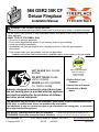
564 GSR2 35K CF
Deluxe Fireplace
Installation Manual
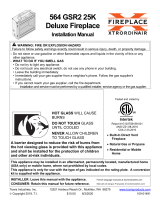
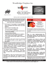
WARNING: FIRE OR EXPLOSION HAZARD
Failure to follow safety warnings exactly could result in serious injury, death, or property damage.
- Do not store or use gasoline or other flammable vapors and liquids in the vicinity of this or any
other appliance.
- WHAT TO DO IF YOU SMELL GAS
• Do not try to light any appliance.
• Do not touch any electrical switch; do not use any phone in your building.
• Leave the building immediately
• Immediately call your gas supplier from a neighbor's phone. Follow the gas supplier's
instructions.
• If you cannot reach your gas supplier, call the fire department.
- Installation and service must be performed by a qualified installer, service agency, or the gas supplier.
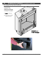
HOT GLASS WILL CAUSE
BURNS
DO NOT TOUCH GLASS
UNTIL COOLED
NEVER ALLOW CHILDREN
TO TOUCH GLASS
A barrier designed to reduce the risk of burns from
the hot viewing glass is provided with this appliance
and shall be installed for the protection of children
and other at-risk individuals.
Listed by
Report # 0028GF080S
ANSI Z21.88-2017
CSA 2.33-2017
CSA 2.17-2017
Built-In Direct Vent
Fireplace
Natural Gas or Propane
Residential or Mobile
Home
This appliance may be installed in an aftermarket, permanently located, manufactured home
(USA only), or mobile home, where not prohibited by local codes.
This appliance is only for use with the type of gas indicated on the rating plate. A conversion
kit is supplied with the appliance.
INSTALLER: Leave this manual with the appliance.
CONSUMER: Retain this manual for future reference.
French language manuals at fireplacex.com
Manuels de langue Française à fireplacex.com
Travis Industries, Inc. 12521 Harbour Reach Dr., Mukilteo, WA 98275 www.travisproducts.com
Copyright 2020, T.I. $10.00 4/23/2021 100-01552

2 Introduction
© Travis Industries 4/23/2021 - 1552 564 GSR2 35K CF
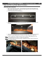
Overview
This manual details the installation
requirements for the 564 GSR2 35K
CF fireplace. For operating and
maintenance instructions, refer to the
564 GSR2 35K CF Owner's Manual.
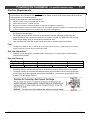
Listing Details
This appliance was listed to ANSI
Z21.88. The listing label is attached
to the appliance near the gas control
valve. A copy is shown to the right.
Massachusetts Approval
This manual has been submitted to
the Massachusetts Board of State
Examiners of Plumbers and Gas
Fitters
National Fireplace Institute

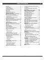
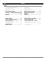
Table of Contents 3
© Travis Industries 4/23/2021 - 1552 564 GSR2 35K CF
Overview ........................................................ 2
Listing Details ................................................ 2
Installation Options ....................................... 6
Heating Specifications .................................. 6
Dimensions .................................................... 6
Packing List ................................................... 7
Additional Items Required ............................ 7
Installation Overview .................................... 7
Recommended Installation Procedure........ 7
Massachusetts Requirements ..................... 8
Requirements for the Commonwealth of
Massachusetts .................................................... 8
MANUFACTURER REQUIREMENTS ................ 8
Pipe Shield Installation ................................. 9
Standoff and Drywall Support Preparation10
Fireplace Placement Requirements .......... 11
Clearances ........................................................ 11
Raised Fireplaces.............................................. 11
Minimum Framing Dimensions .................. 12
Minimum Vent “Bump Out” application –
Top Vent ....................................................... 13
Nailing Brackets .......................................... 14
Corner Installations..................................... 15
Outdoor Fireplace Installations ................. 16
Gas Line Requirements .............................. 17
Fuel ................................................................... 17
Gas Line Connection ......................................... 17
Gas Inlet Pressure............................................. 17
Gas Line Location ............................................. 18
Converting Gas Line to the Left Side................. 18
Electrical Connection (required) ................ 19
Accessing the Area Under the Burner ...... 20
Vent Requirements ...................................... 21
Vent Clearances ................................................ 21
Altitude Considerations ..................................... 21
Approved Vent .................................................. 22
Termination ....................................................... 22
Vent Installation ................................................. 22
Approved Vent Configurations .................. 23
Restrictor Position ............................................. 23
Exhaust Restrictor Adjustment .......................... 23
Intake Restrictor Adjustment ............................. 24
Diffuser Plate Adjustment .................................. 25
Minimum Vent Configuration ..................... 26
Top Vent Configuration with Horizontal
Termination.................................................. 27
Top Vent Configuration with Vertical
Termination.................................................. 28
Masonry Chimney Conversions ................ 29
Class A Chimney Conversion .................... 30
Termination Requirements ........................ 31
Hearth Requirements .................................. 32
Optional Tile Stop Removal ....................... 33
Facing Requirements ................................. 34
Mantel Requirements .................................. 35
Combustible Mantels ......................................... 35
Steps for Finalizing the Installation .......... 36
Air Shutter Adjustment ...................................... 37
Barrier Removal .......................................... 38
Glass Frame Removal and Installation ..... 39
Glass Frame Removal and Installation
(continued)................................................... 40
Ember bed Glass and Ember Material
Installation ................................................... 41
Ember bed Glass Installation ............................ 41
Ember Material Installation ................................ 42
Log Set Installation ..................................... 43
LP Conversion Instructions ....................... 52
Install the LP pilot orifice following the instructions
below. ................................................................ 54
Special Instructions for Fireback
Installation - ................................................. 55
Attaching the Power Heat Duct to the 564
35k (Optional) .............................................. 57
Power Heat Duct Covers ................................. 57
Installing the Power Heat Duct with the 564
35k .................................................................... 59
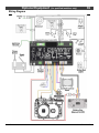
Power Heat Duct Wiring Diagram .................. 59
CoolSmart TV – Installation Overview
(Optional) ..................................................... 60
CoolSmart TV - Installation Requirements .... 61
CoolSmart TV - Reduced Mantel Height ........ 61
CoolSmart TV - Framing the Chase ............... 62
CoolSmart TV - Installation ............................ 63
CoolSmart TV - Using oval pipe to get past an
obstruction ...................................................... 68
Wiring Diagram ........................................... 69
Index ............................................................. 70

4 Safety Precautions
© Travis Industries 4/23/2021 - 1552 564 GSR2 35K CF
Safety Warnings
Failure to follow all of the requirements may result in property damage, bodily injury, or even death.
Young children should be carefully supervised when they are in the same room
as the appliance. Toddlers, young children, and others may be susceptible to
accidental contact burns. A physical barrier is recommended if there are at-risk
individuals in the house. To restrict access to a fireplace or stove, install an
adjustable safety gate to keep toddlers, young children, and other at-risk
individuals out of the room and away from hot surfaces.
Children and adults should be alerted to the hazards of high surface temperature
and should stay away to avoid burns or clothing ignition. Do not touch the hot
surfaces of the heater. Educate all children of the danger of a high-temperature
heater.
Due to the high temperature, the heater should be located out of traffic and away
from furniture and draperies.
This unit must be installed by a qualified installer to prevent the possibility of an explosion.
This appliance must be installed in accordance with all local codes if any; if not, in U.S.A. follow ANSI
Z223.1 and NFPA 54(88), in Canada follow CSA B149.1. In Australia follow AS/NZS 5601.1.
A manufactured home (USA only) or mobile home OEM installation must conform with the
Manufactured Home Construction and Safety Standard, Title 24 CFR, Part 3280, or, when such a
standard is not applicable, the Standard for Manufactured Home Installations, ANSI/NCSBCS
A225.1, or Standard for Gas Equipped Recreational Vehicles and Mobile Housing, CSA Z240.4. This
appliance may be installed in Manufactured Housing only after the home is site located.
All exhaust gases must be vented outside the structure of the living area. Combustion air is drawn
from outside the living-area structure. The venting must not be connected to a chimney flue serving a
separate solid-fuel burning appliance.
Notify your insurance company before hooking up this fireplace.
The instructions in this manual must be strictly adhered to. Do not use makeshift methods or
compromise in the installation. Improper installation will void the warranty and safety listing.
This heater is approved for use with natural gas (NG) or propane (LP). Burning the incorrect fuel will
void the warranty and safety listing and may cause an extreme safety hazard. Direct questions about
the type of fuel used to your dealer.
Contact your local building officials to obtain a permit and information on any installation restrictions
or inspection requirements in your area.
If the flame becomes sooty, dark orange in color, or extremely tall, do not operate the heater. Call
your dealer and arrange for proper servicing.
It is imperative that control compartments, screens, or circulating air passageways of the heater be
kept clean and free of obstructions. These areas provide the air necessary for safe operation.
Do not operate the heater if it is not operating properly in any fashion or if you are uncertain. Call
your dealer for a full explanation of your heater and what to expect.
Do not store or use gasoline or other flammable liquids in the vicinity of this heater.
Do not operate if any portion of the heater was submerged in water or if any corrosion occurs.
Immediately call a qualified service technician to inspect the appliance and to replace any part of the
control system and any gas control which has been underwater.

Safety Precautions 5
© Travis Industries 4/23/2021 - 1552 564 GSR2 35K CF
Safety Warnings (continued)
Because this heater can be controlled by a thermostat there is a possibility of the heater turning on
and igniting any items placed on or near the appliance.
Light the heater using the built-in igniter. Do not use matches or any other external device to light
your heater.
Never remove, replace, modify, or substitute any part of the heater unless instructions are given in
this manual. All other work must be done by a trained technician. Don't modify or replace orifices.
The viewing glass should be opened only for conducting service.
Allow the heater to cool before carrying out any maintenance or cleaning.
Operate the heater according to the instructions included in this manual.
If the main burners do not start correctly turn the gas off and call your dealer for service.
This unit is not for use with solid fuel.
Do not place anything inside the firebox (except the optional artwork).
Warning: Do not operate appliance with the glass front removed, cracked, or broken. Replacement
of the glass should be done by a licensed or qualified service person.
Do not throw this manual away. This manual has important operating and maintenance instructions
that you will need at a later time. Always follow the instructions in this manual.
Instruct everyone in the house how to shut the gas off to the appliance and at the gas main shutoff
valve. The gas main shutoff valve is usually next to the gas meter or propane tank and requires a
wrench to shut off.
A barrier designed to reduce the risk of burns from the hot viewing glass is provided with this
appliance and shall be installed for the protection of children and other at-risk individuals.
If the barrier becomes damaged, the barrier shall be replaced with the manufacturer’s barrier for this
appliance.
Clothing or other flammable material should not be placed on or near the appliance.
Any safety screen, guard, or barrier removed for servicing an appliance must be replaced prior to
operating the appliance.
Installation and repair should be done by a qualified service person. The appliance should be
inspected before use and at least annually by a professional service person. More frequent cleaning
might be required due to excessive lint from carpeting, bedding material, et cetera. It is imperative
that control compartments, burners, and circulating air passageways of the appliance be kept clean.
Travis Industries, Inc. grants no warranty, implied or stated, for the installation or
maintenance of your heater, and assumes no responsibility for any consequential damage(s).
Proposition 65 Warning: Fuels used in gas, woodburning or oil-fired appliances, and the products of combustion of such
fuels, contain chemicals known to the State of California to cause cancer, birth defects, and other reproductive harm.
California Health & Safety Code Sec. 25249.6
Travis Gas Fireplaces, Stoves, and Inserts are protected by one or more of the following patents; U.S. 8,469,021,
7,066,170, 6,602,068, 6,443,726, 6,953,037; Canada 2755517 as well as other U.S. and Foreign Patents pending.

6 Features and Specifications
© Travis Industries 4/23/2021 - 1552 564 GSR2 35K CF
Installation Options
Residential or Mobile Home
Straight or Corner Placement
Flush or Recessed Face
Raised or Floor Placement
Internal or External Chase
Horizontal or Vertical Vent
Bedroom Approved
Heating Specifications
Natural Gas Propane
Approximate Heating Capacity (in square feet)* 1,700 1,700
Maximum BTU Input Per Hour 35,000 35,000
* Heating capacity will vary with floor plan, insulation, and outside temperature.
** Efficiency rating is a product thermal efficiency rating determined under continuous operation
independent of installed system.
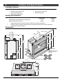
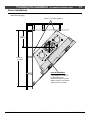
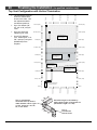
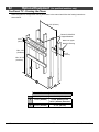
Dimensions
29-3/8"
(746mm)
31-3/4"
37"
(807mm)
(940mm)
*Dimensions Include the standoffs
19-1/8" (486mm)*
4-3/4"
14-3/8"
(121mm)*
(366mm)
* See "Clearances" and "Framing Dimensions" for details.
38-1/4"
(972mm)
Framing Opening
L
e
f
t
a
'
g
a
u
c
h
e
F
r
o
n
t
a
v
a
n
t
R
i
g
h
t
d
r
o
i
t
Baseplate
R
e
a
r
a
r
r
i
e
'
r
e
The bottom of the face is
1/8" (4mm) above the
baseplate.
165 Lbs. (75 Kg)
5-3/4"
(147mm)
19-3/4"
(502mm)
37"
(940mm)
7-5/8"
(194mm)
33-1/8"
(842mm)
32-5/8"
(829mm)
19-1/8" *
(486mm)
29-5/8"*
(752mm)

Finalizing the Installation (for qualified installers only) 7
© Travis Industries 4/23/2021 - 1552 564 GSR2 35K CF
Packing List
Propane Conversion Kit (Front #58 Orifice, Rear #C55 Orifice, Pilot Orifice 0.14 LP).
2 Piece Firestop (sku# 250-05641)
Remote
Embers, Rockwool, Ember-Glass
Pipe shield (attached to the top of the fireplace)
Additional Items Required
Log Set
Vent Pipe (installation specific)
Gas Line Equipment (shutoff valve, pipe, etc.)
Electrical Equipment (min. 14 gauge, grounded line)
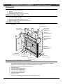
Installation Overview
All requirements below must be met.
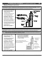
Recommended Installation Procedure
Frame the opening for the fireplace. Make sure to allow for vent installation.
This fireplace is designed to accommodate 1/2" (13mm) or 5/8" (16mm) drywall (see "Nailing
Brackets" on page 13 for details). Secure the fireplace to the framing.
Install the vent, gas line, and electrical hook-up.
Install the drywall.
Install the hearth (if applicable).
Install the facing (if applicable).
Install the mantel (if applicable).
Install the firebacks (optional)
Install the media
Finalize the installation (see page 36) and install the grill or face.
See the section
"Electrical Connection"
See the section
"Mantel Requirements"
Insulation must not fill
the 1/2" (13mm)
clearance around the
back and sides of the
fireplace.
See the section "Minimum
Framing Dimensions"
Drywall
T
op Vent
Configuration
See the section
"Gas Line Installation"
Side
Wall
See the section
See the section
"Approved Vent
"Pipe Shield Installation”
Configurations"
See the section
"Vent Requirements"
See "Optional Non-
Combustible Facing"
Drywall
See "Optional Non-
Combustible Hearth"
Nailing Brackets
1" Min.
25mm

8 Finalizing the Installation (for qualified installers only)
© Travis Industries 4/23/2021 - 1552 564 GSR2 35K CF
Massachusetts Requirements
NOTE: The following requirements reference various Massachusetts and national codes not contained in this document.
Requirements for the Commonwealth of Massachusetts
For all side wall horizontally vented gas fueled equipment installed in every dwelling, building, or structure used in whole or in
part for residential purposes, including those owned or operated by the Commonwealth and where the sidewall exhaust vent
termination is less than seven (7) feet above finished grade in the area of the venting, including but not limited to decks and
porches, the following requirements shall be satisfied:
Installation of Carbon Monoxide Detectors
At the time of installation of the side wall horizontally vented gas fueled equipment, the installing plumber or gasfitter shall
observe that a hard-wired carbon monoxide detector with an alarm and battery back-up is installed on the floor level where the
gas equipment is to be installed. In addition, the installing plumber or gasfitter shall observe that a battery-operated or hard-
wired carbon monoxide detector with an alarm is installed on each additional level of the dwelling, building, or structure served
by the side wall horizontal vented gas fueled equipment. It shall be the responsibility of the property owner to secure the
services of qualified licensed professionals for the installation of hard-wired carbon monoxide detectors.
In the event that the side wall horizontally vented gas fueled equipment is installed in a crawl space or an attic, the hard-wired
carbon monoxide detector with alarm and battery back-up may be installed on the next adjacent floor level.
In the event that the requirements of this subdivision can not be met at the time of completion of installation, the owner shall
have a period of thirty (30) days to comply with the above requirements; provided, however, that during said thirty (30) day
period, a battery-operated carbon monoxide detector with an alarm shall be installed.
Approved Carbon Monoxide Detectors
Each carbon monoxide detector as required in accordance with the above provisions shall comply with NFPA 720 and be
ANSI/UL 2034 listed and IAS certified.
Signage
A metal or plastic identification plate shall be permanently mounted to the exterior of the building at a minimum height of eight
(8) feet above grade directly in line with the exhaust vent terminal for the horizontally vented gas fueled heating appliance or
equipment. The sign shall read, in print size no less than one-half (1/2) inch in size, “GAS VENT DIRECTLY BELOW. KEEP
CLEAR OF ALL OBSTRUCTIONS”.
Inspection
The state or local gas inspector of the side wall horizontally vented gas fueled equipment shall not approve the installation
unless, upon inspection, the inspector observes carbon monoxide detectors and signage installed in accordance with the
provisions of 248 CMR 5.08(2)(a)1 through 4.
Exemptions
The following equipment is exempt from 248 CMR 5.08(2)(a)1 through 4:
• The equipment listed in Chapter 10 entitled “Equipment Not Required To Be Vented” in the most current edition of NFPA 54
as adopted by the Board; and
• Product Approved side wall horizontally vented gas fueled equipment installed in a room or structure separate from the
dwelling, building, or structure used in whole or in part for residential purposes.
MANUFACTURER REQUIREMENTS
Gas Equipment Venting System Provided
When the manufacturer of Product Approved side wall horizontally vented gas equipment provides a venting system design or
venting system components with the equipment, the instructions provided by the manufacturer for installation of the equipment
and the venting system shall include:
• Detailed instructions for the installation of the venting system design or the venting system components; and
• A complete parts list for the venting system design or venting system.
Gas Equipment Venting System NOT Provided
When the manufacturer of a Product Approved side wall horizontally vented gas fueled equipment does not provide the parts
for venting the flue gases but identifies “special venting systems”, the following requirements shall be satisfied by the
manufacturer:
• The referenced “special venting system” instructions shall be included with the appliance or equipment installation
instructions; and
• The “special venting systems” shall be Product Approved by the Board, and the instructions for that system shall include a
parts list and detailed installation instructions.
A copy of all installation instructions for all Product Approved side wall horizontally vented gas fueled equipment, all venting
instructions, all parts lists for venting instructions, and/or all venting design instructions shall remain with the appliance or
equipment at the completion of the installation.
See Gas Connection section for additional Commonwealth of Massachusetts requirements.

Finalizing the Installation (for qualified installers only) 9
© Travis Industries 4/23/2021 - 1552 564 GSR2 35K CF
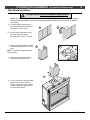
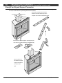
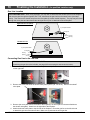
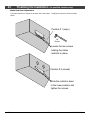
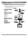
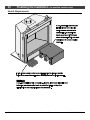
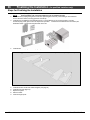
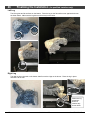
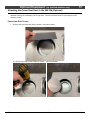
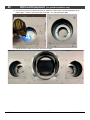
Pipe Shield Installation
The pipe shield must be installed as shown below.
NOTE: The header and pipe shields may be installed after the fireplace is in place and the vent attached
(this allows for the fireplace to fit into the framing underneath the header and for the vent to be installed
more easily).
a) Locate the flattened pipe shield
that was shipped with the fireplace
(attached to header shield).
b) At each of the perforations, bend
the sides of the pipe shield
backward 90° as shown to the right.
c) When the shield has been properly
formed it should look like “c” to the
right.
NOTE: The bottom flanges should be
facing outward
d) Remove the (4) screws, (2) from
each side of the starter collar.
e) Line up the holes on the pipe shield
flanges with the holes from the
screws you just removed. Use the
screws to attach the pipe shield to
the top of the fireplace.
a
c
d
e
b
90

10 Finalizing the Installation (for qualified installers only)
© Travis Industries 4/23/2021 - 1552 564 GSR2 35K CF
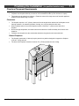
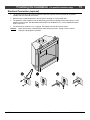
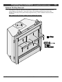
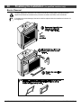
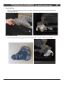
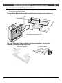
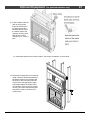
Standoff and Drywall Support Preparation
The two standoffs and three drywall supports are shipped in the flat position. Make sure to bend (and
secure) the standoffs and drywall supports as shown below.
Bend both standoff
s as shown below
.
Remove the screw from the top of the
fireplace and secure the standoff as shown.
When in place, the
standoffs and drywall
supports should look
as shown to the
right.
Bend the three drywall supports up 90 degress (the
outer two are concealed when the standoffs are flat).
The two standoffs are shipped flat.

Finalizing the Installation (for qualified installers only) 11
© Travis Industries 4/23/2021 - 1552 564 GSR2 35K CF
Fireplace Placement Requirements
Fireplace must be installed on a level surface capable of supporting the fireplace and vent
Fireplace must be placed directly on wood or non-combustible surface (not on linoleum or carpet)
This heater may be placed in a bedroom. Please be aware of the large amount of heat this appliance
produces when determining a location.
Clearances
The fireplace requires a 1/2" (13mm) clearance from the angled sides and back of the fireplace to the
framing members. No material (insulation, framing, etc.) may be placed into this area.
When installed, walls in front of the fireplace must be a minimum 1" (25mm) to the side of the
fireplace.
Due to the high temperature, the heater should be located out of traffic and away from furniture and
draperies.
Fireplace must be placed so the vents below and above the glass do not become blocked.
Raised Fireplaces
The fireplace (and hearth, if desired) may be placed on a platform designed to support the fireplace
(155 Lbs. 70 Kg) and vent.
The base of the fireplace must be a minimum 70” (1778mm) below the room ceiling.

12 Finalizing the Installation (for qualified installers only)
© Travis Industries 4/23/2021 - 1552 564 GSR2 35K CF
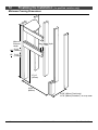
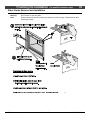
Minimum Framing Dimensions
38-3/4"
(985mm)
19-3/8" (493mm) Flush Install
18-7/8" (480mm) Extended (T
ile Over) Install
37-1/4"
(947mm)
Max. Header Depth
3” (77mm)
Minimum
Enclosure
Height
58-1/4"
70-1/4"
NG
LP
(1480mm)
(1784mm)

Finalizing the Installation (for qualified installers only) 13
© Travis Industries 4/23/2021 - 1552 564 GSR2 35K CF
Minimum Vent “Bump Out” application – Top Vent
564 35K CF
NG Installations
12” Vertical Vent Sections
(Min. Rise)
LP Installations
(2) -12” OR (1) – 24”
Vertical Vent Sections (Min. Rise)
Vent
Centerline
Approx. 48” (1220mm) Approx. 60” to 61” (1524 to 1550mm)
FP Base to
Roof Eave
Approx. 62” (1575mm) Approx. 74” to 75” (1880 to 1905mm)

14 Finalizing the Installation (for qualified installers only)
© Travis Industries 4/23/2021 - 1552 564 GSR2 35K CF
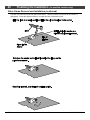
Nailing Brackets
The fireplace has nailing brackets on both sides. Once in place, secure the fireplace to the framing.
NOTE: Make sure the fireplace is square and plumb when securing the fireplace.
SPECIAL NOTE WHEN USING “SUBMERGED FACING” OPTION
Most installations use the “Standard Facing” position for the nailing brackets. When using the
“Submerged Facing” option, the fireplace is positioned ½” to the rear. Make sure to accommodate
this dimension when configuring framing and determining the vent position, gas line position, etc.

Finalizing the Installation (for qualified installers only) 15
© Travis Industries 4/23/2021 - 1552 564 GSR2 35K CF
Corner Installations
A typical 45° installation uses the framing dimensions shown in the illustration below (NOTE: all
clearances still apply).
47-5/8" Min.
(1210mm)
Minimum 1/2" (13mm) Clearance
NOTE ON PIPE SHIELD:
When venting horizontally in a
corner application, one side of
the pipe shield may be
disconnected from the top of the
fireplace and bent in line with the
middle section of the shield.
14-1/4"
(362mm)

16 Finalizing the Installation (for qualified installers only)
© Travis Industries 4/23/2021 - 1552 564 GSR2 35K CF
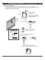
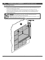
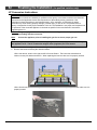
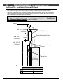
Outdoor Fireplace Installations
Travis Industries Inc. gas-fired fireplaces are
suitable for installation into outdoor areas
protected from direct water impingement. In
addition to maintaining listed mantel and
combustibles clearances, a rain protection
overhang factor of 1/2 shall be constructed to
the front and to each side of installed
appliances (see the illustration to the right). All
wiring connections to line power shall be in
accordance with outdoor requirements of
NECA NFPA 70.

Finalizing the Installation (for qualified installers only) 17
© Travis Industries 4/23/2021 - 1552 564 GSR2 35K CF
Gas Line Requirements
MASSACHUSETTS INSTALLATIONS - WARNING:
THIS PRODUCT MUST BE INSTALLED BY A LICENSED PLUMBER OR GAS FITTER WHEN INSTALLED WITHIN THE
COMMONWEALTH OF MASSACHUSETTS.
OTHER MASSACHUSETTS CODE REQUIREMENTS:
Flexible connector must not be longer than 36 inches.
Shutoff valve must be a “T” handle gas cock.
Only direct vent sealed combustion products are approved for bedrooms or bathrooms.
Fireplace dampers must be removed or welded in the open position prior to the installation of a fireplace insert or gas log.
A carbon monoxide (CO) detector is required in the same room as the appliance.
The gas line must be installed in accordance with all local codes if any; if not, follow ANSI 223.1 and
the requirements listed below.
The fireplace and gas control valve must be disconnected from the gas supply piping during any
pressure testing of that system at test pressures in excess of 1/2 psig. For pressures under 1/2 psig,
isolate the gas supply piping by closing the manual shutoff valve.
Leak test all gas line joints and the gas control valve prior to and after starting the fireplace.
Fuel
This fireplace is designed either for natural gas or for propane (but not for both). Check the sticker on the top of
the gas control valve to make sure the correct fuel is used.
Gas Line Connection
Installation must be performed by a qualified installer, service agency, or the gas supplier (In Massachusetts a
licensed plumber/gasfitter).
Gas Inlet Pressure
Gas Pressure
Max. Input Pressure
Min. Input Pressure
Max. Manifold Pressure
Min. Manifold Pressure
Natural Gas
7" W.C. (1.74 kPA) 5.5” W.C. (1.37 kPA) 3.5” W.C. (0.87 kPA) 1.6” W.C. (0.40 kPA)
Propane
13" W.C. (3.23 kPA) 11” W.C. (2.74 kPA) 11” W.C. (2.74 kPA) 2.9” W.C. (0.72 kPA)
If the pressure is not sufficient, make sure the piping used is large enough, the supply regulator is
adequately adjusted, and the total gas load for the residence does not exceed the amount supplied.
The supply regulator (the regulator that attaches directly to the residence inlet or to the propane tank)
should supply gas at the suggested input pressure listed above. Contact the local gas supplier if the
regulator is at an improper pressure.

18 Finalizing the Installation (for qualified installers only)
© Travis Industries 4/23/2021 - 1552 564 GSR2 35K CF
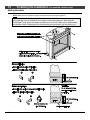
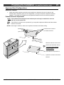
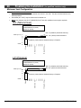
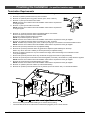
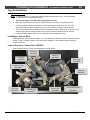
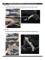
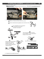
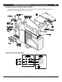
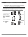
Gas Line Location
NOTE FOR RIGID PIPE: When using rigid pipe, you may wish to disconnect the shutoff valve from the fireplace
and route the pipe through the fireplace wall. First, disconnect the gas line from the shutoff valve (see step 1
below). Then remove the shutoff valve from the cover plate (4 screws outside fireplace). The pipe may be routed
through the cover plate and the shutoff valve and gas line may be re-attached inside the fireplace.
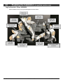
Converting Gas Line to the Left Side
ACCESSING THE AREA UNDER THE BURNER
If switching the gas line to the left side, see page 20 for accessing the area under the burner.
1. Disconnect the gas line from the shutoff valve (3/4” wrench). Gas line is located inside the fireplace
on the right side.
2. Remove the screw that holds the shutoff valve plate in place (1/4” nut driver). Remove the shutoff
valve plate.
3. Remove the cover plate from the left side of the fireplace (it is held in place in the same fashion as
the shutoff valve plate). Attach it to the right side of the fireplace.
4. Attach the shutoff valve plate to the left side of the fireplace. Route the gas line to the left side and
re-attach the gas line to the shutoff valve. Make sure to leak test the entire gas line.
11-1/2"
(293)mm
15 Degrees
3" (77mm) Above Base
8-1/2"
(216mm)
Framing
Framing
Opening
Opening
Right Side Gas Line (Stock)
Left Side Gas Line
3" (77mm) Above Base
15 Degrees

Finalizing the Installation (for qualified installers only) 19
© Travis Industries 4/23/2021 - 1552 564 GSR2 35K CF
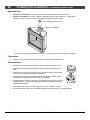
Electrical Connection (required)
The electrical line to the grounded receptacle inside the fireplace must be installed by a qualified
installer and must meet all local codes.
Make sure the household breaker is shut off prior to working on any electrical lines.
The appliance, when installed, must be electrically grounded in accordance with local codes or, in the
absence of local codes, with the National Electrical Code, ANSI/NFPA 70, or the Canadian Electrical
Code, CSA C22.1.
The electrical line must be a min. 14 gauge, and supply 120 Volts at 60 Hz (2 Amps).
Caution: Label all wires prior to disconnection when servicing controls. Wiring errors can cause
improper and dangerous operation.

20 Finalizing the Installation (for qualified installers only)
© Travis Industries 4/23/2021 - 1552 564 GSR2 35K CF
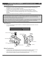
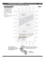
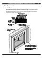
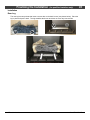
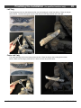
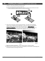
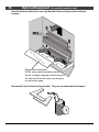
Accessing the Area Under the Burner
The lower panel may be
removed to access
components. This is
required when relocating the
electrical or gas inlet location
or installing the LP regulator.
(a) Loosen the four nuts.
(b) Lift the panel up, rotate it
forward and remove.
Page is loading ...
Page is loading ...
Page is loading ...
Page is loading ...
Page is loading ...
Page is loading ...
Page is loading ...
Page is loading ...
Page is loading ...
Page is loading ...
Page is loading ...
Page is loading ...
Page is loading ...
Page is loading ...
Page is loading ...
Page is loading ...
Page is loading ...
Page is loading ...
Page is loading ...
Page is loading ...
Page is loading ...
Page is loading ...
Page is loading ...
Page is loading ...
Page is loading ...
Page is loading ...
Page is loading ...
Page is loading ...
Page is loading ...
Page is loading ...
Page is loading ...
Page is loading ...
Page is loading ...
Page is loading ...
Page is loading ...
Page is loading ...
Page is loading ...
Page is loading ...
Page is loading ...
Page is loading ...
Page is loading ...
Page is loading ...
Page is loading ...
Page is loading ...
Page is loading ...
Page is loading ...
Page is loading ...
Page is loading ...
Page is loading ...
Page is loading ...
-
 1
1
-
 2
2
-
 3
3
-
 4
4
-
 5
5
-
 6
6
-
 7
7
-
 8
8
-
 9
9
-
 10
10
-
 11
11
-
 12
12
-
 13
13
-
 14
14
-
 15
15
-
 16
16
-
 17
17
-
 18
18
-
 19
19
-
 20
20
-
 21
21
-
 22
22
-
 23
23
-
 24
24
-
 25
25
-
 26
26
-
 27
27
-
 28
28
-
 29
29
-
 30
30
-
 31
31
-
 32
32
-
 33
33
-
 34
34
-
 35
35
-
 36
36
-
 37
37
-
 38
38
-
 39
39
-
 40
40
-
 41
41
-
 42
42
-
 43
43
-
 44
44
-
 45
45
-
 46
46
-
 47
47
-
 48
48
-
 49
49
-
 50
50
-
 51
51
-
 52
52
-
 53
53
-
 54
54
-
 55
55
-
 56
56
-
 57
57
-
 58
58
-
 59
59
-
 60
60
-
 61
61
-
 62
62
-
 63
63
-
 64
64
-
 65
65
-
 66
66
-
 67
67
-
 68
68
-
 69
69
-
 70
70


Fireplace Xtrordinair 564 GSR2 35K CF Installation guide
- Category
- Fireplaces
- Type
- Installation guide
- This manual is also suitable for
Ask a question and I''ll find the answer in the document
Finding information in a document is now easier with AI
Related papers
-
Fireplace Xtrordinair 564 TV 35K Gas Fireplace (FPX) 2020 Installation guide
-
Fireplace Xtrordinair 21 TRV GSR2 Scr Fireplace Bed and Breakfast 2015 Framing Guide
-
-
-
-
 Travis 564 TRV 25K Deluxe Gas Fireplace (FPX) 2018 User manual
-
-
-
-

Other documents
-
Lopi 864 HO GS Owner's manual
-
 GreenSmart 21 TRV Installation guide
-
-
Simpson 616 Owner's manual
-
-
-
Superior Fireplaces VRE3200 Operating instructions
-
Superior VRE3242ZEPWS Installation And Operation Instructions Manual
-
 Woodbridge DVI750 Owner's manual
-
 Woodbridge DVI1000 Owner's manual


