STIEBEL ELTRON WPL 33 HT S Operation and Installation
- Category
- Heat pumps
- Type
- Operation and Installation

OperatiOn and installatiOn
air|Water Heat pump
» Wpl 33 Ht
» Wpl 33 Ht s

2 | WPL 33 HT WWW.STIEBEL-ELTRON.COM
CONTENTS | OPERATION
OPERATION
1. General information �����������������������������������������3
1.1 Document information ������������������������������������������ 3
1.2 Further applicable documents �������������������������������� 3
1.3 Safety instructions ����������������������������������������������� 3
1.4 Other symbols in this documentation ����������������������� 3
1.5 Units of measurement ������������������������������������������ 3
2. Safety ���������������������������������������������������������� 4
2.1 Intended use ������������������������������������������������������ 4
2.2 General safety instructions ������������������������������������ 4
2.3 CE designation ��������������������������������������������������� 4
2.4 Instructions, standards and regulations �������������������� 4
3. Appliance description ���������������������������������������4
3.1 Function ����������������������������������������������������������� 4
4. Settings �������������������������������������������������������5
5. Maintenance and care ���������������������������������������5
6. Troubleshooting ����������������������������������������������5
6.1 Other problems �������������������������������������������������� 5
INSTALLATION
7. Safety ���������������������������������������������������������� 6
7.1 General safety instructions ������������������������������������ 6
7.2 Instructions, standards and regulations �������������������� 6
8. Appliance description ���������������������������������������6
8.1 Standard delivery ������������������������������������������������ 6
8.2 Accessories �������������������������������������������������������� 6
8.3 Buffer cylinder ��������������������������������������������������� 6
9. Preparations ��������������������������������������������������6
9.1 Sound emissions ������������������������������������������������� 6
9.2 Preparation of the installation site ��������������������������� 7
9.3 Electrical installation�������������������������������������������� 9
10. Installation ����������������������������������������������������9
10.1 Handling ����������������������������������������������������������� 9
10.2 External installation ��������������������������������������������� 9
10.3 Internal installation �������������������������������������������� 10
10.4 Heating water connection ������������������������������������� 10
10.5 Condensate drain ����������������������������������������������� 11
10.6 Second heat source��������������������������������������������� 11
10.7 Electrical connection ������������������������������������������� 11
10.8 Casing components �������������������������������������������� 14
10.9 Routing air hoses ����������������������������������������������� 15
10.10 Fitting air hoses ������������������������������������������������� 16
10.11 Insulating the wall outlets ������������������������������������ 16
11. Commissioning ��������������������������������������������� 17
11.1 Checks before commissioning�������������������������������� 17
11.2 Commissioning �������������������������������������������������� 18
12. Taking the appliance out of use �������������������������� 19
12.1 Standby ����������������������������������������������������������� 19
12.2 Power interruption ��������������������������������������������� 19
13. Troubleshooting �������������������������������������������� 19
13.1 Elements on the IWS III HT������������������������������������ 19
13.2 Cleaning the condensate drain ������������������������������� 20
13.3 Resetting the high limit safety cut-out ��������������������� 20
13.4 Sicherheits-Temperaturbegrenzer zurücksetzen ��������� 20
14. Maintenance ������������������������������������������������ 21
15. Specification ������������������������������������������������ 22
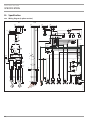
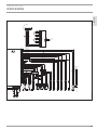
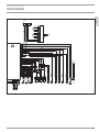
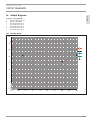
15.1 Wiring diagram (3-phase version) �������������������������� 22
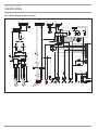
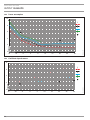
15.2 Wiring diagram (1-phase version) ��������������������������� 24
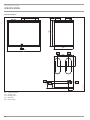
15.3 Connections and dimensions ��������������������������������� 27
15.4 Data table �������������������������������������������������������� 29
16. Output diagrams ������������������������������������������� 31
16.1 Heating output �������������������������������������������������� 31
16.2 Power consumption �������������������������������������������� 32
16.3 Coefficient of performance ����������������������������������� 32
17. Commissioning report ������������������������������������� 33
GUARANTEE
ENVIRONMENT AND RECYCLING

OPERATION
GENERAL INFORMATION
English
WWW.STIEBEL-ELTRON.COM WPL 33 HT | 3
OPERATION
1. General information
1.1 Document information
The chapter entitled “Operation” is intended for appliance users
and qualified contractor.
The chapter entitled “Installation” is intended for qualified con-
tractor.
Note
Read these instructions carefully before using the appli-
ance and retain them for future reference.
Pass on the instructions to a new user if required.
1.2 Further applicable documents
Note
Please observe the operating and installation instructions
of system components.
1.3 Safety instructions
1.3.1 Structure of safety instructions
KEYWORD Type of risk
Here, possible consequences are listed that may result
from failure to observe the safety instructions.
Steps to prevent the risk are listed.
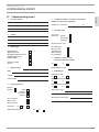
1.3.2 Symbols, type of risk
Read the text next to these symbols carefully.
Symbol Type of risk
!
Injury
Electrocution
Fire
1.3.3 Keywords
KEYWORD Meaning
DANGER Failure to observe this information will result in serious
injury or death.
WARNING Failure to observe this information may result in serious
injury or death.
CAUTION Failure to observe this information may result in non-
serious or minor injury.
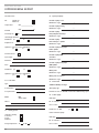
1.4 Other symbols in this documentation
Note
Notes are bordered by horizontal lines above and below
the text. General information is identified by the symbol
shown on the left.
Read these texts carefully.
Symbol
!
Damage to the appliance and the environment
Appliance disposal
Never cover the appliance
This symbol indicates that you have to do something. The ac-
tion you need to take is described step by step.
1.5 Units of measurement
Note
All measurements are given in mm unless stated oth-
erwise.

OPERATION
SAFETY
4 | WPL 33 HT WWW.STIEBEL-ELTRON.COM
2. Safety
Only qualified contractor should carry out installation, commis-
sioning, maintenance and repair of the appliance.
Contractors are responsible for adherence to all currently applica-
ble regulations during installation and commissioning.
2.1 Intended use
The appliance is intended to heat buildings and domestic hot water
(DHW). The appliance is designed for extracting energy from the
air and utilising this energy in water-based heating systems within
the stated operating temperature range.
This appliance is designed for domestic use. It can be safely oper-
ated by untrained personnel. The appliance can also be used in a
non-domestic environment, e.g. in a small business, as long as it
is used in the same way.
Any other use beyond that described shall be deemed inappropri-
ate. Observation of these instructions is also part of the correct use
of this appliance. Any changes or modifications to this appliance
void all warranty rights.
2.2 General safety instructions
Observe the following safety instructions and regulations.
- The electrical installation and installation of the heating cir-
cuit must only be carried out by a recognised, qualified con-
tractor or by our customer service engineers.
- Contractors are responsible for adherence to all currently ap-
plicable regulations during installation and commissioning.
- Operate the appliance only when fully installed and with all
safety equipment fitted.
- Protect the appliance from dust and dirt ingress during
building work.
!
DANGER Injury
Where children or persons with limited physical, sensory
or mental abilities are allowed to control this appliance,
ensure that this will only happen under supervision or
after appropriate instruction by a person responsible for
their safety.
Children must be supervised to ensure that they never
play with the appliance.
2.3 CE designation
The CE designation shows that the appliance meets all essential
requirements according to the:
- Electrical Compatibility Directive (2004/108/EC)
- Low Voltage Directive (2006/95/EC)
- Pressure Equipment Directive (97/23/EC)
2.4 Instructions, standards and regulations
Note
Observe all applicable national and regional regulations
and instructions.
3. Appliance description
The appliance is an air source heat pump that operates as a heating
heat pump. Heat is extracted from the outside air at a low temperature
level, and is then transferred to the heating water at a higher level.
The heating water can be heated up to a flow temperature of 75 °C.
The appliance is equipped with an electric emergency/booster
heater (DHC). In mono mode, the electric emergency/booster
heater is activated when the dual mode point can no longer be
maintained, in order to safeguard heating operation and to pro-
vide high DHW temperatures. In such cases, the electric emer-
gency/booster heater is activated in mono energetic operation as
a booster heater.
Further operational characteristics:
- Suitable for underfloor and radiator heating
- Still extracts heat from the outside air at – 20 °C outside
temperature
- Corrosion-protected, external casing made from zinc-plated
sheet steel plus powder-coated finish.
- Comprises all components required for operation and all
safety equipment.
- Filled with non-combustible safety refrigerant
Note
To control the heating system, you will need the heat
pump manager “WPM 2.1”.
3.1 Function
Heat is extracted from the outside air via the heat exchanger
(evaporator) on the air side. The now evaporated refrigerant is
compressed with one or two compressors. Electrical energy is
necessary for this process. Now, the refrigerant is at a higher
temperature level and transfers the heat drawn from the air via
an additional heat exchanger (condenser) to the heating system.
During this process, the refrigerant expands again, and the cycle
begins again.
At air temperatures below approx. +7 °C, the humidity in the air
condenses as hoarfrost on the evaporator fins. Any hoarfrost is au-
tomatically defrosted. Water created from this defrosting process
collects in the defrost pan and is drained off via a hose.
In the defrost cycle, the fan is switched OFF and the heat pump
circuit is reversed. The heat required for defrosting is drawn from
the buffer cylinder.

OPERATION
SETTINGS
English
WWW.STIEBEL-ELTRON.COM WPL 33 HT | 5
The heat pump automatically reverts to heating mode at the end
of the defrost cycle.
4. Settings
The appliance is controlled by the heat pump manager WPM 2.1
and does not required any special operator actions.
Observe the heat pump manager operating and installation
instructions.
5. Maintenance and care
!
Damage to the appliance and the environment
Maintenance work, such as checking the electrical safety,
must only be carried out by a qualified contractor.
A damp cloth is sufficient for cleaning all plastic and sheet steel
parts. Never use abrasive or corrosive cleaning agents.
Check the condensate drain monthly (visual inspection). Remove
contaminants and blockages immediately.
!
Damage to the appliance and the environment
Keep the air discharge and intake apertures free from
snow and leaves.
We recommend an annual inspection (to establish the current con-
dition of the system), and maintenance by a qualified contractor if
required (to return the system to its original condition).
6. Troubleshooting
Fault Cause
Remedy
There is no hot water or
the heating system stays
cold.
One or more fuses/MCBs
are faulty.
Check the fuse/MCBs in
your fuse box/distribu-
tion panel.
Water collects below the
appliance.
The condensate drain
may be blocked.
Call a qualified contrac-
tor to have the conden-
sate drain cleaned out.
6.1 Other problems
If you cannot remedy the fault, notify your qualified contractor.
To facilitate and speed up your enquiry, please provide the serial
number from the type plate. The type plate is located on the front
at the top on the right or left hand side of the casing.
Sample type plate
Montageanweisung beachten! Dichtheit geprüft!
Made in Germany
*xxxxxxxxxxxxxxxxxx*
26�03�01�1564
1
1 Number on the type plate

6 | WPL 33 HT WWW.STIEBEL-ELTRON.COM
INSTALLATION
SAFETY
INSTALLATION
7. Safety
7.1 General safety instructions
- Only qualified contractor should carry out installation, com-
missioning, maintenance and repair of the appliance.
- We guarantee trouble-free operation and operational reli-
ability only if the original accessories and spare parts intend-
ed for the appliance are used.
7.2 Instructions, standards and regulations
Observe all applicable national and regional regula-
tions and instructions.
8. Appliance description
For external installation the appliance offers additional frost pro-
tection of the heating water pipes. The integral frost protection
circuit starts the circulation pump in the heat pump circuit auto-
matically at +8 °C condenser temperature, and thereby ensures
circulation in all water-filled sections. The heat pump is started
automatically no later than when the temperature inside the buffer
cylinder drops below +5 °C.
8.1 Standard delivery
The following are delivered with the appliance:
- Type plate
8.2 Accessories
8.2.1 Required accessories
You require the following accessories to operate the heat pump:
Description
Heat pump manager 2.1 (WPMS 2.1 or WPMW 2.1)
Remote adjuster for central heating system
Buffer cylinder
Contact sensor
Immersion sensor
Accessory for external installation WPL 33 HT
Accessory for internal installation WPL 33 HT
8.3 Buffer cylinder
A buffer cylinder is absolutely essential to ensure trouble-free
appliance operation. The buffer cylinder is not only installed as a
hydraulic separator for volume flow in the heat pump circuit and
the heating circuit, but primarily as an energy source for defrost-
ing the evaporator.
9. Preparations
9.1 Sound emissions
9.1.1 Sound emissions for external installation
On the air intake and air discharge sides, the appliance is louder
than on the enclosed sides. Please therefore observe the informa-
tion below.
For the sound power level, see chapter “Specification/Data table”.
Ensure that the air intake direction is the same as the main
wind direction. Air should not be drawn in against the wind.
Never direct the air intake or discharge towards noise sensi-
tive rooms of the house (e.g. bedrooms).
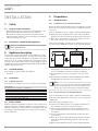
Lawn areas and shrubs contribute to the reduction of noise. For
this, observe the minimum clearances in the following diagram:
≥500
≥1000
≥500
≥500
≥700
D0000019241
Noise can also be reduced through closely spaced palisade
fencing if this is installed around the appliance. For this, ob-
serve the minimum clearances in the previous diagram.
Avoid installation on large, echoing floor areas (e.g. tiled
floors).
Avoid installation between reflective building walls. Reflect-
ing building walls can increase the sound level.
Note
Provide a recess (space) in the substrate to enable water
and electrical pipes/cables to be connected from below.
For this, also observe the chapter “Installation/Siting”.
9.1.2 Acoustic emissions for internal installation
For the sound power level, see chapter “Specification/Data table”.
Never install the appliance directly below or next to living rooms
or bedrooms.
Never install the heat pump on joists.
Isolate the installation surface. See chapter “Preparation of
the installation location for internal installation”.
Connect the heating flow and return via flexible pressure
hoses. Suitable pressure hoses can be found in the accesso-
ries chapter.
Protect all pipe fixings and wall transitions with anti-vibra-
tion insulation.
Never direct the air intake and discharge apertures in exter-
nal walls towards neighbouring windows or living rooms/
bedrooms.
Observe the minimum clearances in the following diagram:

English
WWW.STIEBEL-ELTRON.COM WPL 33 HT | 7
INSTALLATION
PREPARATIONS
≥500
≥500
≥500
≥500
≥1000
D0000019242
9.2 Preparation of the installation site
9.2.1 General information
Ensure that the appliance is accessible from all sides.
- The substrate must be horizontal, level, solid and permanent.
Observe all minimum clearances in chapter “Preparations/
Sound emissions”.
Ensure the entire heat pump frame is in full contact with the
substrate. Uneven substrates can increase noise emissions.
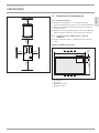
9.2.2 Preparation of the installation site for external
installation
Please observe the chapter “Sound emissions for external
siting”.
Example: Foundations with recess
4
1
2
3
1390
270
50150
800
70
D0000023464
1 Air discharge
2 Air intake
3 Main wind direction
4 Supply line outlet

8 | WPL 33 HT WWW.STIEBEL-ELTRON.COM
INSTALLATION
PREPARATIONS
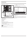
Example: Installation on foundations
26�03�01�1554
1
3
4
5
7
6
8
2
1 Heating circuit flow
2 Main power cable
3 Heating circuit return
4 Conduit for supply lines
5 Electric cables
6 Drainage pipe
7 Gravel bed
8 Foundation
Only use weather-resistant cables.
Protect the flow and return pipes against frost with sufficient
thermal insulation. Provide thermal insulation in accordance
with applicable regulations.
Also protect all supply lines/cables against humidity, damage
and UV radiation by means of a conduit.
Note
When routing the condensate hose, observe chapter “In-
stallation / condensate drain”.
9.2.3 Preparation of the installation site for internal
installation
Observe chapter “Sound emissions for internal installation”.
Isolate the installation surface.
1 2 3 4
26�03�01�1466
1 Concrete base
2 Impact sound insulation
3 Floating screed
4 Recess
See chapter “Specification/Connections and dimensions” for the
position and dimensions of the air intake and discharge apertures,
and the outlets for the water pipes and electrical cables in the
appliance cover.

English
WWW.STIEBEL-ELTRON.COM WPL 33 HT | 9
INSTALLATION
INSTALLATION
9.3 Electrical installation
DANGER Risk of electrocution!
Carry out all electrical connection and installation work
in accordance with national and regional regulations.
DANGER Risk of electrocution!
Only use a permanent connection to the power supply.
The appliance must be able to be separated from the
power supply by an isolator that disconnects all poles
with at least 3 mm contact separation. This requirement
can be met by contactors, circuit breakers, fuses etc.
!
Risk of damage
The specified voltage must match the mains voltage. Ob-
serve the type plate.
Route cables with the following cross-sections in accordance with
the respective fuse rating:
Fuse protec-
tion
Assignment Cable cross-section
C 32 A
C 50 A
Heat pump (3-
phase)
Heat pump (1-
phase)
10.0 mm²
16.0 mm²
B 16 A
Electric emer-
gency/booster
heater (DHC)
(3-phase)
2.5 mm²
C 35 A
Electric emer-
gency/booster
heater (DHC)
(1-phase)
6.0 mm² for routing through a wall
4.0 mm² when routing multi-core cables
on a wall or in an electrical conduit on
a wall
B 16 A Control 1.5 mm²
The electrical specifications are provided in the “Data table”. You
require aJ-Y(St)2x2x0.8mm² cable for the BUS.
Note
Provide separate fuses for the 3 power circuits for the
appliance, the control and the electric emergency/booster
heater.
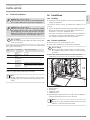
10. Installation
10.1 Handling
Pay attention to the appliance’s centre of gravity when trans-
porting the appliance.
The centre of gravity is in the area where the compressors are
located.
Protect the appliance against heavy impact during transport.
- Only allow the appliance to be tilted during transport for a
short time to one of its longitudinal sides.
The longer the appliance is tilted, the greater the distribution
of refrigerant oil in the system. Wait approx. 30 minutes be-
fore starting the appliance after it has been tilted.
10.2 External installation
Pay attention to the air discharge direction.
Position the standard unit on the prepared substrate.
!
Risk of damage
Observe the torque of the flow meter (see chapter “Spec-
ification/Data table”) when carrying out the following
procedure.
Install pipe bends for the heating circuit flow and return
(components from “Accessories for external installation”).
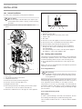
26�03�01�1555
1
2
3
4
5
1 Heating flow
2 Heating return
3 Flow meter
4 Supply line outlet
5 Condensate hose
Route the water pipes and electrical cables into the appliance
from below through the knock-outs in the base.
Note
Only fit the casing components when the electrical and
hydraulic connections have been made.

10 | WPL 33 HT WWW.STIEBEL-ELTRON.COM
INSTALLATION
INSTALLATION
10.3 Internal installation
Position the standard unit on the prepared substrate.
!
Risk of damage
Observe the torque of the flow meter (see chapter “Spec-
ification/Data table”) when carrying out the following
procedure.
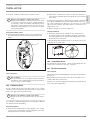
Remove the knock-out at the top in the appliance cover
panel.
1
2
3
4
26�03�01�1685�
1 Connector
2 Union nut
3 Pipe bend for heating circuit return
4 Condensate drain hose
Undo the union nut from the heating flow.
Turn the connector through approx. 45°.
Retighten the union nut.
Install the pipe bend for the heating circuit return (compo-
nent from “Accessories for internal installation”).
Route the condensate hose to the right out of the appliance.
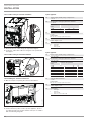
5 4 36
21
26�03�01�1687�
1 Heating return
2 Heating flow
3 Appliance power cable
4 Electric emergency/booster heater power cable
5 Control cable
6 BUS cable
Place the hood on the appliance and secure with two screws.
Cut out the hood to accommodate the water pipe outlets.
Route the water pipes inwards through the hood.
Route the electrical cables from above into the appliance
through the cable entries and through the strain relief fit-
tings (PG fittings).
The open PG fittings are used to route the power supply for
the appliance, control cable and BUS cable.
10.4 Heating water connection
The heating system to which the heat pump is connected must be
installed by a qualified contractor in accordance with the water
installation drawings which are part of the technical guides.
Thoroughly flush the pipework before connecting the heat
pump.
Debris, such as rust, sand and sealant, can impair the operational
reliability of the heat pump.
10.4.1 Oxygen diffusion
!
Risk of damage
In underfloor heating systems with plastic pipes that are
permeable to oxygen, avoid open vented heating systems
or steel pipework.
With permeable plastic underfloor heating system pipes or open
vented heating systems, oxygen diffusion can cause corrosion of
steel components if steel radiators or steel pipes are used.
The products of corrosion, e.g. rusty sludge, can settle inside the
heat pump condenser and result in a lower output by reducing
the cross-section, or in a shutdown being activated by the high
pressure switch.
10.4.2 Filling the heating system
Water quality
In order to prevent damage caused by scale formation, observe
the following when filling the system with heating water:
The total water hardness must be <1°dH(0.18 mmol/l alkaline
earths).

English
WWW.STIEBEL-ELTRON.COM WPL 33 HT | 11
INSTALLATION
INSTALLATION
If the above conditions cannot be met, soften the water.
!
Damage to the appliance and the environment
Fully desalinated water or rainwater must not be used,
as this leads to increased corrosion. Suitable appliances
for softening, as well as the filling and flushing of heat-
ing systems, can be hired from our customer service or
obtained via trade suppliers. You can also use our water
softener fitting HZEA.
Venting the heating system
Vent the pipework carefully. For this, also activate the air
vent valve integrated into the heating flow inside the heat
pump.
1
26�03�01�1690�
1 Air vent valve
10.4.3 Heat meter
!
Risk of damage
For the installation of a heat meter, observe that most
heat meters cause a substantial pressure drop, therefore
choose a larger circulation pump.
10.5 Condensate drain
A hose is fitted at the factory to the defrost pan to act as conden-
sate drain. The hose terminates near the knock-out on the bottom
plate to the right of the refrigeration drive.
!
Damage to the appliance and the environment
Ensure the hose is not kinked. Route the hose with a
slope.
Use a suitable condensate pump if there is insufficient fall. Observe
the delivery head of the building.
External installation
Route the hose downwards out of the appliance. The conden-
sate hose can also be routed out of the appliance to the right
through the knock-out in the side panel.
Channel the condensate into a drain or allow it to drain into a
coarse gravel soakaway. Ensure the pipework is free from the
risk of frost.
If required, you may install a ribbon heater inside the condensate
hose. We recommend that you install a ribbon heater if the rout-
ing of the condensate hose means it is at risk of frost or is fully
exposed to the elements. The ribbon heater is switched on at a
temperature < 0 °C.
Observe chapter on electrical connection.
Internal installation
Route the condensate into a drain. For this, route the hose
through an opening in the floor plate and frame, and route it
out of the appliance to the right by removing the knock-out in
the bottom of the side panel.
In the following diagram the position of the knock-out for the
condensate hose can be seen.
26�03�01�1686�
10.6 Second heat source
For dual mode systems, always connect the heat pump into the
return of the second heat source (e.g. oil boiler).
10.7 Electrical connection
10.7.1 General
Please observe the heat pump manager operating and installation
instructions.
Only qualified electricians must carry out the installation in ac-
cordance with these instructions.
Permission to connect the appliance may need to be obtained from
your local power supply utility.

12 | WPL 33 HT WWW.STIEBEL-ELTRON.COM
INSTALLATION
INSTALLATION
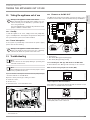
10.7.2 Cable routing for external installation
26�03�01�1559
Route the electric cables along the right-hand support.
Secure the cables with cable ties using the holes provided in
the support.
10.7.3 Cable routing for internal installation
26�03�01�1688�
10.7.4 Making the electrical connections
Observe chapter “Preparing the electrical installation”.
26�03�01�1563
1
1 Connecting chamber
Connect the three power circuits (for the appliance, the elec-
tric emergency/booster heater and the control) in accordance
with the following diagrams.
1-phase appliance
X3 Power supply (heat pump, compressor)
L1, N, PE
X5 DHC (electric emergency/booster heater)
L, L‘, N, PE
Connected
load
Terminal assignment
3.0 kW L N PE
3.2 kW L’ N PE
6.2 kW L L’ N PE
X4 Control cable terminal
L, N, PE
Control inputs:
DHC (electric emergency/booster heater)
X9 Terminal, ribbon heater
Control output: L, N, PE
X2 LV terminal
H BUS high
L BUS low
BUS ground
3-phase appliance
X3 Power supply (heat pump, compressor)
L1, L2, L3, N, PE
X5 DHC (electric emergency/booster heater)
L1, L2, L3, N, PE
Connected
load
Terminal assignment
2.6 kW L1 N PE
3.0 kW L2 N PE
3.2 kW L3 N PE
5.6 kW L1 L2 N PE
5.8 kW L1 L3 N PE
6.2 kW L2 L3 N PE
8.8 kW L1 L2 L3 N PE
X4 Control cable terminal
L, N, PE
Control inputs:
DHC (electric emergency/booster heater)
X9 Terminal, ribbon heater
Control output: L, N, PE
X2 LV terminal
H BUS high
L BUS low
BUS ground
“ + “ BUS “+“ (is not connected)

English
WWW.STIEBEL-ELTRON.COM WPL 33 HT | 13
INSTALLATION
INSTALLATION
1-phase appliance
26�03�01�1556
3-phase appliance
26�03�01�1562

14 | WPL 33 HT WWW.STIEBEL-ELTRON.COM
INSTALLATION
INSTALLATION
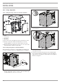
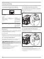
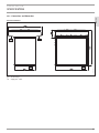
10.8 Casing components
10.8.1 Fitting the casing sections for external installation
2
1
3
1
5
4
26�03�01�0929
1 Side panel
2 Cover
3 Front panel
4 Type plate
5 Back panel
Place the hood on the appliance and secure with two screws.
Hook the side panels and front and back doors onto the
standard appliance. Secure each of these with one screw.
Affix the type plate supplied to top front r.h. or l.h. side of the
side panel where it will be clearly visible.
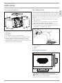
10.8.2 Fitting casing parts for internal installation
Before fitting the casing parts, seal the appliance by affixing plas-
tic sheets. The plastic sheets are supplied with the casing parts.
26�03�01�1692�
Use fabric tape to affix the sheets over the holes at the
bottom of the frame on the r.h. and l.h. sides. The fabric tape
is supplied with the „air hose“ accessories.
26�03�01�1693�
Hang the side sheets with the pre-cut holes onto the hooks
on the appliance.
26�03�01�1694�
Remove the backing from the adhesive tape on the frame and
on the plastic sheets.
Secure the foils by pressing them onto the standard appli-
ance. Seal the apertures around the hooks using adhesive
strips with slits. The adhesive strips with slits are supplied
with the casing parts.

English
WWW.STIEBEL-ELTRON.COM WPL 33 HT | 15
INSTALLATION
INSTALLATION
10.8.3 Fitting casing components
1
5
2
3
4
26�03�01�1689�
1 Cover
2 Front panel
3 L.h. side panel
4 Back panel
5 R.h. side panel, with cut-out in the insulation
Place the hood on the appliance and secure with two screws.
Hook the side panels and front and back doors onto the
standard appliance. Secure each of these with one screw.
Affix the type plate supplied to top front r.h. or l.h. side of the
side panel where it will be clearly visible.
10.9 Routing air hoses
The air hose can be extended by twisting the coils into each other.
There should be an overlap of approx. 30 cm. The total length of
hoses on the air intake and discharge side must not exceed 8 m.
Never incorporate more than four 90 ° bends. The radius of the
bends must be at least 600 mm (relative to the centre line of the
hose).
Cut to size using a sharp knife. The Bowden core can be cut
with wire cutters.
Secure the air hose approximately every 1 m. This prevents
the hose from sagging because of its flexibility.
Match the air hose ends to the shape of the oval connectors
at the hood and the hose connection plates. The hose con-
nection plates are available as accessories.
2
3
1
2
4
26�03�01�0930�
1 Hose connection plate
2 Hose clip (oval)
3 Air hose
4 Cover
Hose connection plate dimensions
1173
778
302
687
D0000017278
!
Damage to the appliance and the environment
Always cover the external apertures with wire grilles.
Secure the hoses against slippage.

16 | WPL 33 HT WWW.STIEBEL-ELTRON.COM
INSTALLATION
INSTALLATION
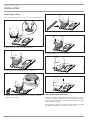
10.10 Fitting air hoses
The example below shows the air hose connection being fitted.
26�03�01�1446
Firstly, push the outer hose slightly upwards.
26�03�01�1447
Push the inner hose halfway down the connector.
26�03�01�1448
Seal the inner hose by affixing it to the connector using the
fabric tape provided.
26�03�01�1449
Place the sealing strip provided around the connector.
26�03�01�1450
Pull the outer hose over the connector.
26�03�01�1452
Secure the hose using the oval hose clip provided.
26�03�01�1453
10.11 Insulating the wall outlets
Prevent cold bridges forming between the wall outlets to be in-
stalled on site and the brickwork. To prevent condensation form-
ing in the brickwork, insert suitable insulation between the wall
outlets and the brickwork.
As an alternative, you can also use the insulated wall outlet AWG
560. Wall outlet AWG 560 is available as an accessory.

English
WWW.STIEBEL-ELTRON.COM WPL 33 HT | 17
INSTALLATION
COMMISSIONING
11. Commissioning
A WPM2.1 heat pump manager is required to operate the appli-
ance. All necessary adjustments prior to and during operation are
made on this device.
Only qualified contractors may carry out the adjustments on the
heat pump manager commissioning list, commission the appliance
and instruct the owner in its use.
Commissioning is to be carried out in accordance with these instal-
lation instructions and the operating and installation instructions
of the heat pump manager. Our customer service can assist in the
commissioning, which is chargeable.
Where this appliance is intended for commercial use, the rules of
the relevant Health & Safety at Work Act may be applicable for
commissioning. For further details, check your local authorising
body.
After commissioning, complete the commissioning report that is
part of these instructions.
11.1 Checks before commissioning
Before commissioning, check the following points:
11.1.1 Heating system
- Have you filled the heating system to the correct pressure,
and opened the quick-acting air vent valve?
11.1.2 Temperature sensor
- Have you correctly placed and connected the outside tem-
perature sensor and the external return temperature sensor
(in conjunction with a buffer cylinder)?
11.1.3 High limit safety cut-out
At ambient temperatures below -15°C it may happen that the
high limit safety cut-out triggers the emergency/booster heater.
Check whether the high limit safety cut-out has responded.
26�03�01�1565
1
2
1 High limit safety cut-out reset button
2 Electric emergency/booster heater
Reset the high limit safety cut-out by pressing the reset
button.
11.1.4 Power supply
- Have you correctly connected the power supply?

18 | WPL 33 HT WWW.STIEBEL-ELTRON.COM
INSTALLATION
COMMISSIONING
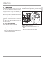
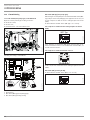
11.2 Commissioning
11.2.1 DIP switch (heat pump type) on the IWS III HT
Open the control panel by proceeding as follows:
Undo the screws,
lift the cover,
and remove the cover towards the front.
26�03�01�1557
Checking the settings on the IWS III
BA
26�03�01�1691�
1
4
3 2
1 LED
2 Reset button
3 DIP switch (WP-Typ [heat pump type])
4 DIP switch (BA [operating mode])
DIP switch (WP-Typ [heat pump type])
Different types of heat pump are selected with the DIP switch (WP-
Typ). Subject to the heat pump type, the appliance was factory-set
for two compressors with an electric emergency/booster heater
(DHC).
Check whether the DIP switch (WP-Typ) is set correctly.
Two compressors with an electric emergency/booster heater
(DHC):
WP-Typ
26�03�01�1513
If the appliance is operated in dual mode operation with an ex-
ternal second heat source or as module with a further WPL, set
the DIP switch as follows:
Two compressors with external heat source 2:
26�03�01�1514
In this case, do not connect the electric emergency/booster heater
(DHC).
DIP switch (BA [operating mode])
Check whether the DIP switch(BA) is set correctly.
BA
26�03�01�1515

English
WWW.STIEBEL-ELTRON.COM WPL 33 HT | 19
INSTALLATION
TAKING THE APPLIANCE OUT OF USE
12. Taking the appliance out of use
!
Damage to the appliance and the environment
Never interrupt the heat pump power supply, even out-
side the heating season. Otherwise, system frost protec-
tion is not guaranteed.
The heat pump manager automatically switches the heat
pump to summer or winter mode.
12.1 Standby
To take the appliance out of use, simply set the heat pump man-
ager to “Standby mode”. That way the safety functions that protect
the system and frost protection remain enabled.
12.2 Power interruption
If the system is permanently isolated from the power supply,
please observe the following:
!
Damage to the appliance and the environment
If the heat pump and frost protection are completely
switched off, drain the system on the water side.
13. Troubleshooting
Note
Please observe the heat pump manager operating and
installation instructions.
Note
The following inspection instructions may only be carried
out by a qualified contractor.
If you are unable to identify this fault with the heat pump manager,
check the elements on the IWS III HT.
Open the control panel by proceeding as follows:
Undo the screws,
lift the cover,
and remove the cover towards the front.
26�03�01�1557
Read the following sections on troubleshooting and carry out
the instructions.
13.1 Elements on the IWS III HT
The IWS III HT (integral heat pump controller III) helps you to
troubleshoot if the fault cannot be identified using the WPM 2.1.
BA
26�03�01�1691�
1
4
3 2
1 LED
2 Reset button
3 DIP switch (WP-Typ [heat pump type])
4 DIP switch (BA [operating mode])
13.1.1 Checking the “WP-Typ” DIP switch on the IWSIIIHT
Check whether the “WP-Typ”DIP switch (3) is set as follows:
With an electric emergency/booster heater (DHC)
WP-Typ
26�03�01�1513
Single compressor with external HS 2.
If the appliance is operated in dual mode with an external second
heat source, set the DIP switch as follows:
26�03�01�1439
In this case the power supply for the electric emergency/booster
heater (DHC) must not be connected.

20 | WPL 33 HT WWW.STIEBEL-ELTRON.COM
INSTALLATION
TROUBLESHOOTING
13.1.2 Checking the “BA” DIP switch on the IWS III HT
Check whether the “BA” DIP switch (4) is set as follows:
BA
26�03�01�1436
13.1.3 LED (1)
Red LED
Fault Cause » Remedy
Appliance stops and
restarts after the idle
period has expired. Red
LED flashes.
Heat pump fault.
Check the fault mes-
sage in the WPM. Find
the solution in the WPM
instructions (fault list).
Perform a reset of the
IWS (see WPM instruc-
tions).
Appliance stops perma-
nently. Red LED illumi-
nates.
Five faults within two
hours compressor runt-
ime.
Check the fault mes-
sage in the WPM. Find
the solution in the WPM
instructions (fault list).
Perform a reset of the
IWS (see WPM instruc-
tions).
Green LED centre
The LED flashes during initialisation, and illuminates constantly
after the BUS address has been assigned successfully. Only then
is communication with WPM2.1 established.
13.1.4 Reset button
If the IWS was incorrectly initialised, the settings can be reset with
this button. For this also observe the chapter “Reinitialising IWS”
in the heat pump manager operating and installation instructions.
13.2 Cleaning the condensate drain
Environmental conditions may result in the condensate drain be-
coming blocked. To clean the drain, proceed as follows:
DANGER Risk of electrocution!
Before removing the casing components, disconnect all
poles from the power supply.
Remove the casing parts
(see chapter “Installation”).
Check the hose and the pipe of the condensate drain.
Remove dirt and blockages immediately.
Refit the casing parts on the appliance.
(see chapter “Installation”).
13.3 Resetting the high limit safety cut-out
The electric emergency/booster heater (DHC) stops if the heating
water temperature exceeds 85 °C on account of a low flow rate.
Remove the cause of the fault.
Reset the high limit safety cut-out. For this, press the button
shown:
26�03�01�1565
1
1 High limit safety cut-out reset button
13.4 Resetting the high limit safety cut-out
If the heating water temperature exceeds 85°C, the electric emer-
gency/booster heater shuts down.
Remove the cause of the fault.
26�03�01�1565
1
2
1 High limit safety cut-out reset button
2 Electric emergency/booster heater
Reset the high limit safety cut-out by pressing the reset but-
ton. If necessary, use a pointed object to do so.
Check whether the heating water is being circulated at a suf-
ficient flow rate.
Page is loading ...
Page is loading ...
Page is loading ...
Page is loading ...
Page is loading ...
Page is loading ...
Page is loading ...
Page is loading ...
Page is loading ...
Page is loading ...
Page is loading ...
Page is loading ...
Page is loading ...
Page is loading ...
Page is loading ...
Page is loading ...
Page is loading ...
Page is loading ...
Page is loading ...
Page is loading ...
-
 1
1
-
 2
2
-
 3
3
-
 4
4
-
 5
5
-
 6
6
-
 7
7
-
 8
8
-
 9
9
-
 10
10
-
 11
11
-
 12
12
-
 13
13
-
 14
14
-
 15
15
-
 16
16
-
 17
17
-
 18
18
-
 19
19
-
 20
20
-
 21
21
-
 22
22
-
 23
23
-
 24
24
-
 25
25
-
 26
26
-
 27
27
-
 28
28
-
 29
29
-
 30
30
-
 31
31
-
 32
32
-
 33
33
-
 34
34
-
 35
35
-
 36
36
-
 37
37
-
 38
38
-
 39
39
-
 40
40


STIEBEL ELTRON WPL 33 HT S Operation and Installation
- Category
- Heat pumps
- Type
- Operation and Installation
Ask a question and I''ll find the answer in the document
Finding information in a document is now easier with AI
Related papers
-
STIEBEL ELTRON WPL 19-24_I_IK_A Operation Instruction
-
-
-
-
-
-
-
-
-
Other documents
-
SVA VR-20 User manual
-
-
Room Board 60W User manual
-
 ORE Lighting Installation guide
-
STECA tr a501 t User manual
-
 Merco Products DHC-24 User manual
-
Sony TC-TX333 User manual
-
Primare i21 User manual
-
 Titan Distributors Inc. Titan Overhead Storage Rack | 4' x 4' | Adjustable Height User manual
-
 STOKVIS ENERGY SYSTEMS ECONOPLATE H1 Installation, Commissioning And Servicing Instructions


