Advantech BB-485HESP Quick start guide

Type
Quick start guide
Recommended Accessories
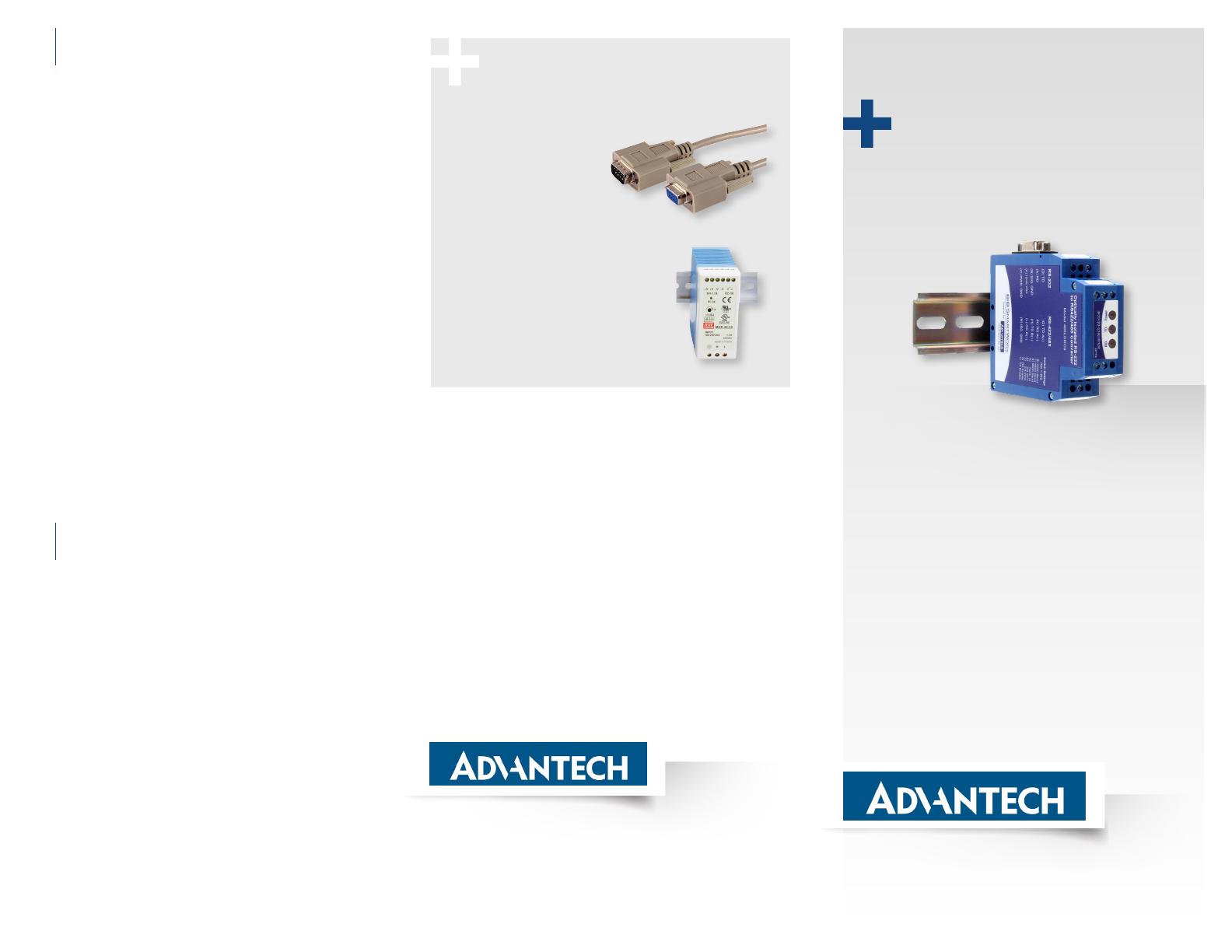
Serial Cable
Model BB-9PAMF6
Industrial Power Supply
Model BB-MDR-40-24
Document Number: 20BB710-10764-00_r2_BB-485LDRC9_4619qsg
www.advantech.com
707 Dayton Road | PO Box 1040 | Ottawa, IL 61350 USA
Phone: 1 (815) 433-5100 | Fax: 1 (815) 433-5109
www.advantech.com | E-mail: support@advantech-bb.com
Before you begin, be sure
you have the following:
Model BB-485LDRC9
RS-422/485 Converter, Industrial
Fast and easy on the web:
www.advantech.com
+ Model BB-485LDRC9 Serial Converter
+ Required, but not included:
- Power Supply
- RS-232 Cable
- RS-422/485 Cable
QUICK START
GUIDE
Timing Issues?
(Usually applies when using RS-485 2-wire)
Model BB-485LDRC9 uses RC time constant. This means that, when
you are setting the DIP switches for the “baud rate”, you are setting a
turnaround time, not a “baud rate”.
Sometimes, the turnaround time on an RS-485 2-wire device does not
match the turnaround time that is set on the BB-485LDRC9 converter,
even though they are both set for the same baud rate. Refer to the
chart in Step 3 to match the turnaround time of your RS-485 2-wire
device. If you do not know the turnaround time of your device, you can
do the following:
Keep your device at its current baud rate, but change the
“baud rate” on the BB-485LDRC9. Set it for one or two steps
above or below the baud rate of your device until you get
communication.
Alternatively, you can use Model BB-485DRCi-PH instead of
the BB-485LDRC9. Model 485DRCi-PH uses bit-wise control
so you do not have to worry about matching the timing of your
device.
Note: Do Not use the shield drain wire as the Signal Ground between
RS-422/485 devices. RS-422/485 systems may communicate
successfully without the Signal Ground when nodes are located
close together and circuit grounds for all nodes are at the same
potential – e.g., a controlled lab environment. However, this practice
is not recommended. If a Signal Ground is not used when nodes
are separated by distance, and there is the possibility of lightning
and/or other electrical noise, the common mode voltage can rise to
levels that could compromise communications, or even damage the
transceivers in the system nodes.
Troubleshooting
8
UL Installation Information
Underwriters Laboratories Conditions of Acceptability
– When installed in the end-use equipment, consideration should be
given to the following:
1. The wiring terminals are suitable for factory wiring only.
2. This device is to be mounted in a suitable enclosure in the end-
product.
3. This device is suitable for operation at a maximum surrounding air
temperature as described in the documentation.
4. These devices are intended for use in a Pollution Degree 2
environment.
Input Voltage: 10 – 30 VDC
Input Power: 0.5 Watts
Wire Range: 12 – 24 AWG
Tightening Torque: 4 kgf-cm
• TemperatureRatingofeldinstalledconductorsis105°C
minimum,sizedfor60°Campacity.
Use copper wire only.
• Maximumsurroundingambientairtemperature80°C.
UL Installation Information
9
Product Overview
Connect RS-232 Device
Set RS-422/485 Converter Side
Termination Switch:
Set to OFF (recommended)
Connect Your Power Supply
Loopback Test
Set the Dipswitch Settings
for Baud Rate
1
+
+
+
+
2
4
5
6
3
External Power
Supply
Terminal C:
(Ground/V (–)
Terminal F:
V (+)
Converter uses 0.5 W
•CongureforRS-4854-wire,9600baud.
• Jumper terminals H to L, and G to K.
• Connect a PC to RS-232 port (see Step 1).
• Using HyperTerminal or similar program,
connect to the appropriate COM port
(remember to set the baud rate at 9600).
Turn off HyperTerminal local echo.
• Start typing. If you can see the data
you are typing, you have a good loop-
back. If you cannot, contact Advantech
B+B Technical Support.
• LED Indicators: Power is ON when power
isapplied.TDasheswhenRS-422/485
dataissent.RDasheswhenRS-
422/485 data is received.
Set DIP
Switches to:
RS-485
4-Wire
L
K
H
G
1
2
3
4
5
6
7
8
ON
ON
OFF
OFF
OFF
OFF
OFF
OFF
LED Indicators
7
+
Terminal Block
Connectors
A – F
Terminal Block
Connectors
G – M
DB9 Female
Pins
DIP
Switches
1 – 8
Top View
(RS-232 & Power Side)
Bottom View
(RS-422/485 Side)
Note:
Terminal block and DIP switch settings located on product.
Additional RS-422/485 technical notes are
available on the website.
2-Wire 485 4-Wire 485/422
Your Device Your DeviceBB-485LDRC9 BB-485LDRC9
G
K
DATA
B (+)
DATA
A (-)
GND
H
L
J
M
G
TDB
(+)
TDA
(-)
RDB
(+)
RDA
(-)
GND
K
H
L
J
M
SW-1 SW-2 SW-3 SW-4
RS-485 2-Wire Half-Duplex ON ON ON ON
RS-485 4-Wire Full-Duplex ON OFF OFF OFF
RS-422 Full-Duplex OFF OFF OFF OFF
Computer
Your Device485LDRC9
Field Device
Your Device485LDRC9
DTE DCE
D
TD
RD
A
E
B
F
C
GND
D
TD
RD
GND
A
E
B
F
C
Additional technical notes on RS-232 DTE & DCE
connections are available on the website.
Use a straight-through DB9 to DB9 if you are
connecting to a computer (DTE).
Use a cross-over (null modem) DB9 to DB9 if you are
not connecting to a computer. (DCE)
For baud rates not listed above, see the website.
SW-6 SW-7 SW-8 Timeout (MS)
2400 OFF OFF ON 4.16
4800 OFF ON OFF 2.08
9600 ON OFF OFF 1.04
19.2K ON ON ON 0.580
Switch 5
Termination technical notes are available
on the website.
Use the 120Ω
Built-in Termination
ON
Use External or
No Termination
OFF
Transmit Data (Red) Flashing - RS-422/485 data is transmitted.
Receive Data (Red) Flashing - RS-422/485 data is received.
Power (Red) On - when power applied.
With no devices attached, LEDs should be Off; Power On.
TIPS:
If LEDs are On before devices are attached, it may indicate that the
Termination Resistor is On.
Using termination with power ON, but no devices connected, may cause
the Receive LED to turn ON solid. The loading from the termination may
cause the Receiver Bias to go into an indeterminate state.
  • Page 1 1
  • Page 2 2

Advantech BB-485HESP Quick start guide

Type
Quick start guide

Ask a question and I''ll find the answer in the document

Finding information in a document is now easier with AI