Page is loading ...

Page 1
98986C (Rev. A - 5/12)
HTHBHVR*A HTHBHVRBL*A HTHBHVR8*1A HTHBHVR8BL*1A
HTHBHVR8 Factory Prep
Hydroboost Bottle Filling Station and Cooler
HTHBHVR8 Bottle Fillers are among the easiest to install on the market today. To
insure you install these models easily and correctly, PLEASE READ THESE SIM-
PLE INSTRUCTIONS BEFORE STARTING THE INSTALLATION. CHECK YOUR
INSTALLATION FOR COMPLIANCE WITH PLUMBING, ELECTRICAL, AND
OTHER APPLICABLE CODES. After installation, leave these instructions with the
Fountain for future reference.
IMPORTANT
THIS IS AN INDOOR APPLICATION ONLY.
ALL SERVICE TO BE PERFORMED BY AN
AUTHORIZED SERVICE PERSON.
IMPORTANT! INSTALLER PLEASE NOTE.
THE GROUNDING OF ELECTRICAL EQUIPMENT SUCH AS TELEPHONE, COMPUTERS, ETC. TO WATER
LINES IS A COMMON PROCEDURE. THIS GROUNDING MAY BE IN THE BUILDING OR MAY OCCUR AWAY
FROM THE BUILDING. THIS GROUNDING CAN CAUSE ELECTRICAL FEEDBACK INTO A FOUNTAIN, CREAT-
ING AN ELECTROLYSIS WHICH CAUSES A METALLIC TASTE OR AN INCREASE IN THE METAL CONTENT
OF THE WATER. THIS CONDITION IS AVOIDABLE BY USING THE PROPER MATERIALS AS INDICATED. ANY
DRAIN FITTINGS PROVIDED BY THE INSTALLER SHOULD BE MADE OF PLASTIC TO ELECTRICALLY ISO-
LATE THE FOUNTAIN FROM THE BUILDING PLUMBING SYSTEM. WE SUGGEST THAT THE BOTTLE FILLING
STATION AND WATER COOLER BE PROTECTED BY A GROUND FAULT CIRCUIT INTERRUPTER (GFCI).
INSTALLER
TOOLS REQUIRED
BUT NOT PROVIDED:
SAFETY GLASSES
GLOVES
ELECTRIC DRILL
3/4” WRENCH OR CRECENT WRENCH
UTILITY KNIFE
TAPE MEASURE
PENCIL
CENTER PUNCH
1/2” SOCKET & RATCHET WRENCH
5/32” ALLEN WRENCH
Installation/Care/Use Manual

Page 2
98986C (Rev. A - 5/12)
HTHBHVR*A HTHBHVRBL*A HTHBHVR8*1A HTHBHVR8BL*1A
2-7/16"
63mm
3-1/2"
89mm
4-1/2"
114mm
5"
127mm
10"
254mm
13-7/8"
352mm
2-1/2"
63mm
11/16"
18mm
4-9/16"
116mm
2-9/16"
65mm
7-1/4"
185mm
18-3/8"
467mm
21-3/8"
543mm
25"
635mm
F
A
D
B
E
E
31"
788mm
49-1/2"
1257mm
18-1/2"
470mm
FINISHED FLOOR
12-5/16"
312mm
6-3/4"
171mm
6-1/4"
159mm
1-1/2"
38mm
2-5/8"
66mm
8"
203mm
C
27"
686mm
*
31-15/16"
811mm
RIM HEIGHT
33-1/16"
840mm
ORIFICE
HEIGHT
18-9/16"
472mm
51-1/8"
1298mm
5-1/8"
131mm
48"
1219mm
O
5/16"
8mm
MOUNTING
HOLES (3 PL)
1/4" X 1/2" (6mm X 13mm)
OBROUND HOLE (5 PL)
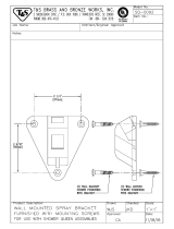
HANGER BRACKET
7"
178mm
7"
178mm
16-5/16"
414mm
1-1/4"
32mm
1-1/4"
32mm
Single Rough-In
Fig. 1
HTHBHVR8
* REDUCE HEIGHT BY 3” FOR INSTALLATION OF CHILDRENS ADA COOLER
LEGEND:
A = RECOMMENDED WATER SUPPLY LOCATION 3/8” O.D. UNPLATED COPPER TUBE CONNECT STUB 1-1/2”
(38mm)
OUT FROM WALL. SHUT OFF VALVE NOT FURNISHED.
B = RECOMMENDED LOCATION FOR WASTE OUTLET 1-1/4” O.D. DRAIN.
C = 1-1/4” TRAP NOT FURNISHED.
D = ELECTRICAL SUPPLY (3) WIRE RECESSED BOX, DUPLEX OUTLET REQUIRED.
E = INSURE PROPER VENTILATION BY MAINTAINING 6” (152mm) MIN. CLEARANCE FROM CABINET LOUVER TO
WALL.
F = 7/16” BOLT HOLES FOR FASTENING UNITS TO WALL.

Page 3
98986C (Rev. A - 5/12)
HTHBHVR*A HTHBHVRBL*A HTHBHVR8*1A HTHBHVR8BL*1A
C
L
C
L
13-7/8"
352mm
18-3/4"
476mm
20-1/8"
511mm
25-1/8"
638mm
5"
127mm
2-7/16"
63mm
10"
254mm
20-3/8"
518mm
37-1/2"
952mm
2-9/16"
65mm
7-1/4"
185mm
6-1/2"
165mm
11/16"
18mm
4-9/16"
116mm
O
5/16"
8mm
HOLES
(5 PL)
FINISHED FLOOR
F
A
E
D
B
F
E
C
6-3/4"
171mm
12-5/16"
313mm
33-1/16"
840mm
ORIFICE
HEIGHT
39-9/16"
1005mm
ORIFICE
HEIGHT
HANGER
BRACKET
1/4" X 1/2" (6mm X 13mm)
OBROUND HOLE (5 PL)
27"
686mm
*
48"
1219mm
2-5/8"
67mm
18-9/16"
472mm
5-1/8"
131mm
4-1/8"
105mm
51-1/8"
1298mm
31-15/16"
811mm
RIM HEIGHT
8"
203mm
18-1/16"
459mm
7"
178mm
7"
178mm
1-1/4"
32mm
1-1/4"
32mm
16-5/16"
414mm
O
5/16"
8mm
HOLES
(3 PL)
5-3/4"
146mm
5-3/4"
146mm
1-3/8"
35mm
1-3/8"
35mm
18-1/2"
470mm
3-1/2"
89mm
4-1/2"
114mm
6-1/4"
159mm
Two -Level Rough-In
Fig. 2
HTHBHVR8BL
* REDUCE HEIGHT BY 3” FOR INSTALLATION OF CHILDRENS ADA COOLER
LEGEND:
A = RECOMMENDED WATER SUPPLY LOCATION 3/8” O.D. UNPLATED COPPER TUBE CONNECT STUB 1-1/2”
(38mm)
OUT FROM WALL. SHUT OFF VALVE NOT FURNISHED.
B = RECOMMENDED LOCATION FOR WASTE OUTLET 1-1/4” O.D. DRAIN.
C = 1-1/2” TRAP NOT FURNISHED.
D = ELECTRICAL SUPPLY (3) WIRE RECESSED BOX, DUPLEX OUTLET REQUIRED.
E = INSURE PROPER VENTILATION BY MAINTAINING 6” (152mm) MIN. CLEARANCE FROM CABINET LOUVER TO
WALL.
F = 7/16” BOLT HOLES FOR FASTENING UNITS TO WALL.

Page 4
98986C (Rev. A - 5/12)
HTHBHVR*A HTHBHVRBL*A HTHBHVR8*1A HTHBHVR8BL*1A
Fig. 4
Note: Screw the locknut hand tight to seal
Fig. 5
MOUNTING SCREWS
WATER COOLER
MOUNTING SCREW
DO NOT REMOVE
MOUNTING BRACKET
FOR FASTENING UNIT
TO WALL
Fig. 3
TOP COVER
BOTTLE FILLER
MOUNTING SCREW
DO NOT REMOVE
BOTTLE FILLER INSTALLATION
1) Remove wall mounting plate(s) from Cooler(s). Install Wall Mounting Plate(s) as per rough-in diagrams on sheet 2 or 3 of this instruction.
NOTE: Mounting plate(s) MUST be supported securely. Add xture support carrier if wall will not provide adequate support.
2) For Single Model Installations: Install water cooler onto wall bracket and secure to wall. Connect drain and water inlet to cooler as required (See rough-
in on page 2). DO NOT connect power to cooler at this time or turn water supply on.
2a) For Bi-Level Model Installations: Install lower water cooler only at this time onto bracket as per rough-in diagram on sheet 3.
3) Remove VRC Bottle Filler from carton. Remove 3/8” to 1/4” reducing union from end of waterline, (do not throw away it will be needed later). Lay Bottle Filler
on water cooler basin and cut insulation from tube even with bottom of unit, remove this insulation from the 3/8” tube, but do not discard. Fish the power
cord, and waterline through the hole on top of water cooler. Fish the Reset Button wire from circuit board down through the hole in the basin.
NOTE: To prevent scratching the basin place a towel or soft cloth over the entire basin when working above it.
4) With the power cord, waterline and reset button wires through the hole on top of water cooler place Bottle Filler on to mounting bracket on basin.
(See Fig. 3). Make sure bottle ller is installed properly on the basin gasket.
5) Once Bottle Filler is installed on basin mounting bracket, tighten the two screws (supplied) one on each side of the bottle ller. Install Top Cover on Bottle
Filler (See FIG. 3) with two mounting screws (supplied) . Caution do not over tighten screws.
6) For Bi-Level Model Installations: Secure non-refrigerated unit to wall, connect drains and water inlet. Connect black reset button wires from
non-refrigerated unit to the black wires on the refrigerated unit (see step 4).
7) For Single Model Installations: Install remaining tube insulation to the water line from bottle ller, connect Bottle Filler waterline inside of the water cooler
by connecting the 3/8” water line with the 3/8” to 1/4” union and short piece of poly tube that was previously installed to the tee at the evaporator outlet.
7a) For Bi-Level Model Installations: Install the 1/4” poly tubing and insulation from the outlet of the lter to the union on top of the evaporator. Install the
1/4” poly tubing and insulation from the regulator in the non-refrigerated cooler to one of the tees at the evaporator outlet. Install remaining tube insulation
to the water line from bottle ller, connect Bottle Filler waterline inside of the water cooler by connecting the 3/8” water line with the 3/8” to 1/4” union and
short piece of poly tube that was previously installed to the tee at the evaporator on the refrigerated cooler.
8) Install lter cartridge, remove lter from carton, remove protective cap, attach lter to lter head by rmly inserting into head and rotating lter clockwise.
NOTE: If existing plumbing rough-in locations (Drain, Water In, Electric Supply) do not allow the lter to be mounted inside the cooler cabinet
the lter can be installed horizontally below the unit. A retrot kit is available to mount the lter beneath the cooler.
9) Turn water supply on and inspect for leaks. Fix all leaks before continuing.
10) Once unit has been inspected for leaks and any leaks found corrected plug Bottle Filler and HVR unit into wall. Be sure to reinstall fuse to the circuit
or switch the circuit breaker back to the “ON” position.
11) Once power is applied to Bottle Filler, the GREEN LED light should illuminate showing good lter status along with the LCD Bottle Counter.
12) Verify proper dispensing by depressing the button at the top of the Bottle Filler and verify water dispenses. Note: the rst initial dispenses
might have air in line which may cause a sputter. This will be eliminated once all air is purged from the line.
14) Once unit tests out, install Lower Panel back on HVR water cooler(s). Units are now ready for use.
NOTE: TRIM PLATES MUST
BE INSTALLED ON THE
INSIDE OF THE BOTTLE
FILLER SIDE PANEL SLOTS

Page 5
98986C (Rev. A - 5/12)
HTHBHVR*A HTHBHVRBL*A HTHBHVR8*1A HTHBHVR8BL*1A
STANDARD TWO-LEVEL CONFIGURATION
STANDARD TWO-LEVEL REVERSED CONFIGURATION
1/4” HEX. HEAD BOLT THIS LOCATION ONLY
REMOVAL OF BOTTLE FILLER FOR SERVICING
1) Turn off the water supply to the Water Cooler(s). Unplug and/or turn off Circuit Braker to Cooler(s) and Bottle Filler. NOTE: the Lower Front Panel
of the cooler(s) may need to be removed. To prevent scratching the basin place a towel or soft cloth over the entire basin when working above it.
2) For Single Model Installations: Loosen but DO NOT remove the two (2) Pinned Torx Head Screws from the sides of the Bottle Filler. Remove the
two (2) Pinned Torx Head Screws from the Top Cover & remove the Top Cover. The Bottle Filler may then be lifted up and off the Water Cooler
(The water line and Remote Reset Button Wires will still be connected from the Water Cooler to the Bottle Filler.).
3) For Two Level Model Installations: Loosen but DO NOT remove the Pinned Torx Head Screw from the outer side of the Bottle Filler and loosen but
DO NOT remove the 1/4” hex. head bolt from between the two cooler (See Figs 6 or 7). Remove the two (2) Pinned Torx Head Screws from the Top
Cover & remove the Top Cover. The Bottle Filler may then be lifted up and off the Water Cooler (The water line and Remote Reset Button Wires will
still be connected from the Water Cooler to the Bottle Filler.).
Fig. 6
Fig. 7
1/4” HEX. HEAD BOLT THIS LOCATION ONLY

Page 6
98986C (Rev. A - 5/12)
HTHBHVR*A HTHBHVRBL*A HTHBHVR8*1A HTHBHVR8BL*1A
BF9 PROGRAM
SETTING THE CONTROL BOARD
VERIFY CONTROL BOARD SOFTWARE
1) To verify the software program of the control board the
unit will need to be shut down and restarted. The chiller
(if present) does not need to be shut down and restarted.
2) The units lower panel must be open to access the power
cord and wall outlet.
3) Shut down the unit by unplugging the power cord from the
wall outlet.
4) Restart the unit by plugging the power cord back into the
wall outlet.
5) Upon start up the bottle count display will show the
software designation of BF9.
ACCESSING THE PROGRAMING BUTTON
1) To access the program button remove the bottom cover of
the water cooler. The reset button is located on the left side
of the cooler near the cold control. Replace the bottom
cover after programming operations are completed.
NOTE: There is a reset button located under the top cover
on the left hand side of the bottle ller also.
RESET THE FILTER MONITOR
1) Instructions apply to ltered units only.
2) Depress the program button for approximately 2 seconds
until the display changes then release. The display will
change and scroll through two messages:
“RST FLTR” – Reset Filter Monitor
“SETTINGS” – System Settings Sub Menu
If the program button is not pushed again the display
will scroll through the two messages above for
three cycles and then default back to bottle count and
be back in run mode.
3) When the display changes to “RST FLTR”, depress
the button again. The display will change to show
“FLT =”. Depress the button again and the display
will show “FLTR =0”
4) The Green LED should be illuminated indicating that
the visual lter monitor has been reset.
SETTING UNIT TYPE
1) Depress the program button for approximately 2 seconds
until the display changes then release. The display will
change and scroll through two messages:
“RST FLTR” – Reset Filter Status LED
“SETTINGS” – System Settings Sub Menu
If the program button is not pushed again the display
will scroll through the two messages above for
three cycles and then default back to bottle count
and be back in run mode.
2) When the display changes to “SETTINGS”, depress
the button again. The display will change to show
“RNG SET“- Range set for IR sensor.
“UNIT TYP“ - Type of unit (REFRIG or NON-REFRIG)
“RST BCNT“ - Reset bottle count
3) When display shows “UNIT TYPE” push program
button once the display will show current value
Can be REFRIG or NON-REFRIG
4) Push button once to change value. Once value is
selected the display will show the new value.
(Can be REFRIG or NON-REFRIG)
“REFRIG“ - stands for refrigerated product. In this
setting the ow rate is estimated at 1.0 gallon per minute.
“NON-REFRIG“ - stands for non-refrigerated product.
In this setting the ow rate is estimated
at 1.5 gallons per minute.
Both “REFRIG“ and “NON-REFRIG“ simulated
1 bottle equal to 20 oz.
5) Allow approximately 4 seconds to pass and the display
will return to bottle counter and be in run mode.
RESETTING BOTTLE COUNT
1) Depress the program button for approximately 2 seconds
until the display changes then release. The display will
change and scroll through two messages:
“RST FLTR” – Reset Filter Status LED
“SETTINGS” – System Settings Sub Menu
If the program button is not pushed again the display
will scroll through the two messages above for
three cycles and then default back to bottle count
and be back in run mode.
2) When the display changes to “SETTINGS”, depress
the button again. The display will change to show
“RNG SET“- Range set for IR sensor.
“UNIT TYP“ - Type of unit (REFRIG or NON-REFRIG)
“RST BCNT“ - Reset bottle count
If the button is not pushed again the display will scroll
through the three messages above for three cycles and
return to run mode.
3) When display shows “RST BCNT” push program button
once the display will show current value i.e. “000033183”.
4) Once display shows current value push the program
button once more to reset back to 0. The display will
show BTLCT = 0 for approximately 2 seconds and
then return to run mode showing 00000000 bottles.
5) To test bottle counter:
REFRIG units: Push and hold Bottle Filler Button for
9.4 seconds to see bottle counter count 00000001.
(This is based on lling a 20 oz. bottle).
NON-REFRIG units: Push and hold Bottle Filler Button for
6.25 seconds to see bottle counter count 00000001.
(This is based on lling a 20 oz. bottle)

Page 7
98986C (Rev. A - 5/12)
HTHBHVR*A HTHBHVRBL*A HTHBHVR8*1A HTHBHVR8BL*1A
1
2
3
4
5
6
7
Fig. 7
WATER FILTER EXPLODED VIEW
DESCRIPTION
1
2
3
4
5
6
7
ITEM NO. PART NO.
51294C
70792C
70823C
70822C
55898C
70818C
28641C
Filter Head Assy.
Screw #8-18 x .75 PH
Fitting - Superseal 3/8” (10 mm)
Fitting - Superseal 1/4” (6 mm)
Filter Assy
Elbow - 3/8” (10mm)
Bracket
DESCRIPCIÓN DESCRIPTION
Ensamblado de la Cabeza del Filtro
Tornillo #8-18 x .75 PH
Accesorio - Supersello 3/8” (10mm)
Accesorio - Supersello 1/4” (6 mm)
Ensamblado del Filtro
Codo - 3/8” (10 mm)
Fijador
Ens. de tête de ltre
Vis #8-18 x .75 hp
Raccord - Superseal 3/8” (10mm)
Raccord - Superseal 1/4” (6mm)
Ens. ltre
Coude - 3/8” (10mm)
Support
WATERSENTRY
®
PLUS FILTER PARTS LIST
(See Fig. 7)
LISTA DE PIEZAS DEL FIL-
TRO (Vea Fig. 7)
LISTE DES PIÈCES DU FIL-
TRE (Voir Fig. 7)
PRINTED IN U.S.A.
FOR PARTS CONTACT YOUR LOCAL DISTRIBUTOR OR VISIT OUR WEBSITE WWW.HALSEYTAYLOR.COM
PARA PIEZAS DE REEMPLAZO PÓNGASE EN CONTACTO CON SU DISTRIBUIDOR LOCAL O VISITE NUESTRO SITIO DE WEB WWW.HALSEYTAYLOR.COM
POUR VOUS PROCURER DES PIOCES, CONTACTEZ VOTRE DISTRIBUTEUR LOCAL OU VISITEZ NOTRE SITE WEB A L’ADRESSE WWW.HALSEYTAYLOR.COM
2222 CAMDEN COURT
OAK BROOK, IL 60523
630.574.3500
DESCRIPTION
98543C
98545C
98546C
98549C
98552C
98668C
98999C
99000C
99001C
99002C
99003C
99004C
Kit - Electrical Package
Kit - Solenoid Valve Replacement
Kit - Aerator Replacement
Kit - Hardware & Waterway Parts
Kit - Retro Filter Mounting
Kit - Filter Mounting Cover
Kit - Drain Pad
Kit - Button Assembly
Kit - Top Cover Replacement
Kit - Basin/Tower Gasket
Kit - Reset Switch
Kit - Micro Switch
REPLACEMENT PART KITS
PART NO.
/