Bauer 64425 Owner's manual
- Category
- Power tools
- Type
- Owner's manual
This manual is also suitable for
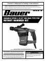
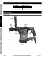
Bauer Item 64425 is a Variable Speed 1-9/16" SDS MAX-Type PRO Rotary Hammer Kit. It is a powerful tool designed for a variety of tasks, including drilling, chipping, and breaking. The rotary hammer features a variable speed motor that allows you to match the speed to the task at hand. It also has a SDS MAX chuck that makes it easy to change bits. The kit includes a variety of bits and accessories, so you can get started right away.
Here are some of the features and capabilities of the Bauer Item 64425:
- Powerful motor for drilling, chipping, and breaking
- Variable speed motor for matching the speed to the task


-
 1
1
-
 2
2
-
 3
3
-
 4
4
-
 5
5
-
 6
6
-
 7
7
-
 8
8
-
 9
9
-
 10
10
-
 11
11
-
 12
12
-
 13
13
-
 14
14
-
 15
15
-
 16
16


Bauer 64425 Owner's manual
- Category
- Power tools
- Type
- Owner's manual
- This manual is also suitable for
Bauer Item 64425 is a Variable Speed 1-9/16" SDS MAX-Type PRO Rotary Hammer Kit. It is a powerful tool designed for a variety of tasks, including drilling, chipping, and breaking. The rotary hammer features a variable speed motor that allows you to match the speed to the task at hand. It also has a SDS MAX chuck that makes it easy to change bits. The kit includes a variety of bits and accessories, so you can get started right away.
Here are some of the features and capabilities of the Bauer Item 64425:
- Powerful motor for drilling, chipping, and breaking
- Variable speed motor for matching the speed to the task
Ask a question and I''ll find the answer in the document
Finding information in a document is now easier with AI
Related papers
-
Bauer 63988 Owner's manual
-
-
Bauer 1632E-B Owner's manual
-
-
-
-
-
-
-
Other documents
-
Hercules 56407 Owner's manual
-
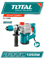 Total TH110286 Owner's manual
-
SPEEDWAY 45137 User manual
-
XtremepowerUS 61117-XPH1 User manual
-
Ronix 2701 User manual
-
Chicago Electric Item 60610 Owner's manual
-
-
Grizzly T10446 User manual
-
-
