Page is loading ...

SSM33I
SUMP/EFFLUENT PUMPS
(115 Volt-Single Phase Only)
SRM4
SUMP/EFFLUENT/SEWAGE PUMPS
(115 or 230 Volt-Single Phase)
OWNER’S MANUAL
Submersible Sump Effluent
© 2017 Pentair Ltd. All Rights Reserved.
MY13800A991 (09/08/17)
293 WRIGHT STREET, DELAVAN, WI 53115 WWW.FEMYERS.COM
PH:
1-888-987-8677

2
12
3
4
9
10
11
12
5
6
8
13
14
15
16
17
18
19
7
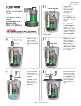
TYPICAL SECTION DRAWING FOR SSM33/SSM33I SERIES
20 Piggy-Back Control
Control Vertical Float Switch
10’ Cord
Control Vertical Float Switch
20’ Cord. Not Shown
(Automatic Only)
21
Cable Tie. Not Shown
(Automatic Only)

3
20 Piggy-Back Control
21
Cable Tie
Not Shown
(Automatic Only)
TYPICAL SECTION DRAWING FOR SRM4 SERIES

4
PARTS LIST SSM33/SSM33I AND SRM4
CHART
Ref
No.
No.
Description
Part
Req’d Numbers
2 Ring, Lift 1 26230A000
3 Plug, 1/4” NPT 1 05022A056
4 Plate, Name (Not Stamped) 1 23780A000
5 Tapping, Screw (SSM33/SSM33I) 1 09822A032
5 Tapping, Screw (SRM4P Auto.) 1 09822A006
5A
Screw, Cap #10 x ¾ Vertical
Float Switch
2 18475A004
6 Oil, Transformer (1 Qt. In Can) 1 11009A002
8 Rotor with Shaft (SSM33/SSM33I) 1 22821A010
8 Rotor with Shaft (SRM4) 1 22821A000
9 Washer, Thrust, SST 1 05030A243
10 Washer, Thrust, Graphite 1 05030A244
11 Housing, Motor 1 23770D002
Housing w/Stator
115V (SRM4P) 23770D060K
230V (SRM4P) 23770D061K
115V (SSM33/SSM33I) 23770D062K
12 Seal, ½” Shaft 1 21607A001
13 Gasket, Rubber 1 05014A172
14 Screw, Cap, 1/4-20 x 7/8 Lg.
(SSM33/SSM33I) 3 18475A003
(SRM4) 6 18475A003
15 Case, Volute (SSM33) 1 23771D001
15 Case, Volute (SSM33I) 1 23771D101
16 Impeller (SSM33) 1 22370B000
16 Impeller (SSM33I) 1 084980031
17 Plate, Bottom, with Volute Case 1 27005D000
Ref
No.
No.
Description
Part
Req’d Numbers
18 Screw, Tapping, #10 x 1” Lg.
(SSM33, SRM4)
3 09822A036
18 Screw, Tapping, #10 x ¾” Lg.
(SSM33I)
3 18475A008
19 Screw, Tapping, #10 x 1¾” Lg.
(SSM33, SRM4)
3 09822A040
19 Screw, Tapping, #10 x 1-5/8” Lg.
(SSM33I)
3 18475A009
20 Control, Level, 115V, 10’
Piggy-Back Float Switch
1 21813B130
20 Control, Level, 115V, 20’
Piggy-Back Float Switch
1 21813B131
20 Control, Level, 230V, 10’
Piggy-Back Float Switch
1 21813B132
20 Control, Level, 230V, 20’
Piggy-Back Float Switch
1 21813B133
20 Vertical Control Switch - 10’ Cord 1 26292B140
20 Vertical Control Switch - 20’ Cord 1 26292B141
20 Diaphragm Control Switch - 20’ Cord 1 149740195-01
20A Mounting Bracket, Control Switch 1 26291B010
21 Tie, Cable 1 17190A008
22 Plate, Seal (SRM4) 1 23773D002
23 Case, Volute (SRM4) 1 21612D000
24 Impeller (SRM4) 1 21610B000
Not
Shown
Bracket, Float (SSM33/SSM33I) 1 24003A000
Not
Shown
Bracket for Diaphragm
(SRM4D-1 Only)
1 055020111
Pump
Catalog
Number
Pump
Engineering
Number
Pump
Switch HP V Ph
1
Cord,
Electric
Cord
Length
7
Stator
Only
Winding
Resistance
in Ohms
Max.
Amps
Locked
Rotor
Amps
Switch
On Off
SSM33IM1C 26235D100 Manual 1/3 115 1 21628B048 20' 22757B010 1. 3 9 12.5 - -
SSM33IP-1 26235D110 Automatic 1/3 115 1 21628B046 10' 22757B010 1. 3 9 12.5 9 - 15/16" 4 - 1/16"
SSM33IPC-1 26235D111 Automatic 1/3 115 1 21628B048 20' 22757B010 1.3 9 12.5 9 - 15/16" 4 - 1/16"
SSM33IPV1 26235D120 Automatic 1/3 115 1 21628B046 10' 22757B010 1. 3 9 12.5 5 - 7/8" 1 - 3/4"
SSM33IPV1C 26235D121 Automatic 1/3 115 1 21628B048 20' 22757B010 1.3 9 12.5 5 - 7/8" 1 - 3/4"
SRM4M1C 26236D001 Manual 4/10 115 1 21628B048 20' 21599B026 1. 2 12 16 - -
SRM4M2C 26236D003 Manual 4/10 230 1 21628B049 20' 21599B027 4.3 6 8.2 - -
SRM4P-1 26236D010 Automatic 4/10 115 1 21628B046 10' 21599B026 1. 2 12 16 13 - 7/8" 8 - 1/8"
SRM4PC-1 26236D011 Automatic 4/10 115 1 21628B048 20' 21599B026 1. 2 12 16 13 - 7/8" 8 - 1/8"
SRM4PC-2 26236D013 Automatic 4/10 230 1 21628B049 20' 21599B027 4.3 6 8.2 13 - 7/8" 8 - 1/8"
SRM4V-1 26236D041 Automatic 4/10 115 1 21628B048 20' 21599B026 1. 2 12 16 6 - 1/4" 2 - 7/8"
SRM4V-2 26236D043 Automatic 4/10 230 1 21628B049 20' 21599B027 4.3 6 8.2 6 - 1/4" 2 - 7/8"
SRM4D-1 26236D061 Automatic 4/10 115 1 21628B048 20' 21599B026 1. 2 12 16 11" 3"

5
NOTE: READ THESE INSTRUCTIONS
CAREFULLY BEFORE ATTEMPTING TO
INSTALL PUMP.
DESCRIPTION AND APPLICATION
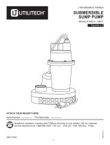
SSM33, SSM33I and SRM4
Myers SSM33, SSM33I and SRM4 Series Pumps are single
seal units, available in automatic or manual. The SSM33 and
SSM33I series pumps are designed for normal sump and
dewatering, and can also be used in effluent applications.
When used in effluent dosing or S.T.E.P. applications,the
pump must be installed in a separate tank or compartment
at the discharge side of the septic tank. NEVER INSTALL
PUMP IN MAIN TANK WHERE SLUDGE COLLECTS. DO
NOT USE THE SSM33 OR SSM33I PUMP SERIES FOR
RAW SEWAGE. The SRM4 series pumps are designed for
residential sewage and dewatering applications where a
larger solid size is required.
General
The SSM33, SSM33I and SRM4 pumps use shaded pole,
1550 RPM motors. SSM33 and SSM33I are available in 115
volt only and the SRM4 is available in 115 or 230 volt and
all are single phase only. Both the manual and automatic
models come standard with a 10 ft. power cord. A 20 ft. cord
and switch length are optionally available. All automatic
models come with a mechanical (mercury free) piggy-back
float switch or a vertical float switch. The SSM33 and SSM33I
pumps are designed to handle 1/2” spherical solids and have
a 1-1/2” NPT discharge threading. The SRM4 pumps are
designed to handle 2” spherical solids and have a 2” NPT
discharge threading. The SSM33, SSM33I and the SRM4
use an engineered thermoplastic vortex impeller designed to
efficiently produce the required pressures and flows.
WARNING! THESE PUMPS ARE NOT APPROVED FOR,
AND SHOULD NOT BE USED IN SWIMMING POOLS,
FOUNTAINS OR PUMPING POTABLE (DRINKING)
WATER.
AIR LOCKING
A pump is said to be air locked if water traps air in the
pump and it cannot get out, thus preventing the pump from
operating.
The SSM33, SSM33I and SRM4 sump pumps have a 1/16”
air vent hole in the impeller chamber to let out trapped
air. If this hole becomes plugged, pump may air lock. As a
secondary precaution a 1/8” hole should be drilled in the
discharge pipe below the check valve. The check valve
should be 12 to 18 inches above pump discharge. Do not put
check valve directly into pump discharge opening.
PACKAGING
Each pump is packaged separately in a carton marked with a
catalog number and Myers engineering number. The pumps
are carefully packaged to prevent damage in shipping.
However, occasionally damage may result due to rough
handling. Carefully go over the pump and check for damage
that could cause the pump to fail.
LEVEL CONTROLS
The automatic models come with 10’ or 20’ power cord and
mechanical (mercury free), piggy-back float switch. The 115
or 230 volt piggy-back switch is tethered directly to the pump.
The switch can optionally be mounted to the discharge pipe
using a minimum 3-5/8” tether length. The switch must float
free from pump and basin wall. Plug the switch cord plug
into a properly grounded, rated voltage receptacle. Plug the
power cord into the back of the switch cord and tape the
cords to the discharge pipe every 12”. The power receptacle
must be located outside the wet sump or basin due to the
DANGER of current leakage.
On all duplex units or simplex installations with additional
options like high water alarm, the power cord plug must be
cut off and wired into a control panel or into a sealed junction
box if used in wet sump or basin. The AWS-1 control also
acts as a sealed junction box for connecting power cord to
pump cord.
DESIGN OF PRESSURE SEWER SYSTEMS
Myers has available complete computer SOFTWARE for
designing PRESSURE SEWER SYSTEMS. This gives pipe
sizes to use and gives exact flow from any pump or group of
pumps in the system when operating simultaneously.
This design DISK for IBM
®
or COMPATIBLE computers is
available to engineers on request.
MOTOR TYPE
The motors used in these pumps are pressed into the cast
iron housings and surrounded by dielectric oil for superior
heat transfer. Both models use a shaded pole, 1550 RPM
motor. The SSM33 and SSM33I are rated at 1/3 HP and
the SRM4 is rated at 4/10 HP. All units have class A motor
insulation. SSM33 and SSM33I are available in 115 volt,
single phase only and SRM4 is available in 115 or 230
volt, single phase. All have overload protection, and use a
double sleeve bearing design. These pumps have no starting
switches and do not require a control panel for simplex
installation.
SAFETY WARNINGS
WARNING: Risk of electric shock. Pumps are supplied with
a grounding conductor and grounding-type attachment plug
on the power cord. To reduce the risk of electric shock, be
certain that it is connected only to a properly grounded,
grounding-type receptacle. DO NOT cut off ground pin or use
an adapter fitting. DO NOT use an extension cord with this
pump.
All pumps have a GROUND WIRE that is connected to the
motor. This wire goes to the receptacle or control panel which
must be connected to a good outside GROUND.
When wiring this pump follow all local electrical and safety
codes and ordinances as well as the most recent National
Electric Code (NEC-ANSI/NFPA 70).
CALIFORNIA PROPOSITION 65 WARNING:
This product and related accessories
contain chemicals known to the State of California to cause
cancer, birth defects or other reproductive harm.

6
CSA APPROVED
All pumps have CSA approval. Myers is a SSPMA certified
pump member.
INSTALLATION
WARNING: Basin or tank must be vented in accordance with
local plumbing codes. These pumps are not designed for and
CANNOT be installed in locations classified as hazardous in
accordance with the National Electric Code ANSI/NFPA 70.
CAUTION: Never enter pump chamber after sewage or
effluent has been in basin. Sewage water can give off
methane, hydrogen sulfide and other gasses which are
highly poisonous. For this reason, Myers recommends
installing effluent pumps with a quick removal system. The
quick removal system may be a union or coupling if the pipe
or discharge hose is within reach from the surface, or a rail
system type quick disconnect on deeper installations. See
installation drawings for suggested installation.
The dosing tank or pumping chamber must be constructed
of corrosion resistant materials and must be capable of
withstanding all anticipated internal and external loads. It
also must not allow infiltration or exfiltration. The tank must
have provisions for anti-buoyancy. Access holes or covers
must be adequate size and be accessible from the surface to
allow for installation and maintenance of the system. Access
covers must be lockable or heavy enough to prevent easy
access by unauthorized personnel. The pumping chamber
holding capacity should be selected to allow for emergency
conditions.
The discharge pipe must be the same size as the pump
discharge 1-1/2” for SSM33 and SSM33I, 2” for SRM4 or
larger. In order to insure sufficient fluid velocity to prevent
any residual solids from collecting in the discharge pipe, it
is recommended that a minimum flow of 2’ per second be
maintained. (12 GPM through 1-1/2” pipe, 21 GPM through
2” pipe and 46 GPM through 3” pipe). It is recommended that
PVC or equal pipe is used for corrosion resistance. A full flow
(ball or gate) shut off valve must be installed to prevent back
flow of effluent if the pump must be removed for service. A
check valve must be installed on pressure sewer systems
and on other systems where conditions allow to prevent
backflow and to reduce wear on the pump system.
A high water alarm must be installed on a separate circuit
from the pump circuit. The alarm should have the ability to be
tested for proper operation.
POINTS TO CHECK IF PUMP DOES NOT
RUN OR DOES NOT RUN PROPERLY
(1) Pump does not run or start when water is up in tank.
(a) Check for blown fuse or tripped circuit breaker.
(b) Check for defective level switch
(c) Where control panel is used be sure H-O-A switch is
in the AUTO position. If it does not run, turn switch
to the HAND position and if the pump runs then the
trouble is in the automatic electrical system. Have
ELECTRICIAN make electrical checks.
(d) Check for burned out motor. Occasionally lightning
can damage a motor even with lightning protection.
(e) Where plug-in cords are used be sure contact blades
are clean and making good contact. DO NOT USE
PLUG-IN CORDS INSIDE A SUMP OR WET WELL.
(f) Level control ball or weight may be stuck on side of
basin. Be sure it floats freely.
(2) Pump runs but does not deliver flow.
(a) Check for airlock. Start and stop pump several times,
if this does not help it may be necessary to loosen a
union in the discharge line to relieve airlock.
(b) Check valve may be installed backwards. Check flow
arrow on valve body. Check shut-off valve. It may be
closed.
(c) Check vertical elevation. It may be higher than pump
can develop. (See pump curve).
(d) Pump inlet may be plugged. Remove pump to check.
CAUTION: ALWAYS UNPLUG POWER CORDS OR TURN
OFF ALL MAIN AND BRANCH CIRCUIT BREAKERS
BEFORE DOING ANY WORK ON THE PUMP. If control
panel is remote from pump, disconnect lead wires to motor
so that no one can turn the circuit breaker back on.
BEFORE DISMANTLING PUMP FOR
REPLACEMENT OF PARTS
Clean pump thoroughly. Knock off all scale and deposits.
Submerge complete unit on Clorox solution for one hour
before taking apart.

7
TYPICAL SUMP INSTALLATION FOR SSM33/SSM33I Series

8
TYPICAL SUMP INSTALLATION FOR SRM4 SERIES

9
CAUTION: FOR ANY WORK ON PUMP
OR SWITCH, ALWAYS UNPLUG POWER
CORD. DO NOT JUST TURN OFF CIRCUIT
BREAKER OR UNSCREW FUSE.
TO REPLACE AUTOMATIC FLOAT
(1) Unplug the pump power cord from the back of the
piggyback float plug.
(2) Unplug the piggy-back float plug from the power
receptacle.
(3) Remove the pump from the sump if access to the tether
point is inaccessible.
(4) Disconnect the switch from its tether point and remove
from the discharge piping.
(5) Re-tether the new cord to the pump or discharge piping.
(6) Cable tie or tape the power and switch cords to the
discharge piping.
(7) Plug the switch into the power receptacle.
(8) Plug the power cord into the switch plug.
(9) Fill basin and test switch operation.
ALL PUMP REPAIRS SHOULD BE DONE AT AN
AUTHORIZED MYERS SERVICE CENTER.
TO REPLACE THE AUTOMATIC
VERTICAL FLOAT SWITCH
(1) Unplug the pump power cord from the back of the piggy-
back plug.
(2) Unplug the piggy-back plug from the power receptacle.
(3) Remove the two mounting screws in the switch bracket
that attached the switch assembly to the pump and
remove from the discharge piping.
(4) Mount new switch assembly to pump. Be sure to install
plastic tie provided and re-tether to mounting screw.
(5) Cable tie or tape the power and switch cords to the
discharge piping.
(6) Plug the piggy-back switch in the power receptacle.
(7) Plug power cord into the piggy-back switch plug.
(8) Fill basin and test switch operation.
TO REPLACE THE AUTOMATIC VERTICAL
AND DIAPHRAGM FLOAT SWITCH
(1) Remove the oil fill plug located on the top of the motor
housing and drain the oil in the housing. Properly
dispose of the used oil. Do not reuse old oil since it may
contain water from seal failure.
(2) Lay the pump on its side. Remove the six screws holding
the suction bottom onto the volute case. Remove the
suction bottom.
(3) Insert a slotted screwdriver through the center of the
impeller hub into the slot in the shaft. With a rubber
mallet, carefully tap the impeller in a counter rotating
direction while holding the shaft with the screwdriver.
(4) Remove the rotating portion (ceramic) of the seal with
fingers. Pry on the stationary portion (carbon) with a pair
of slotted screwdrivers to remove from volute casing.
Discard the old seal assembly parts. NEVER USE OLD
SEAL PARTS, REBUILD PUMP WITH ONLY NEW
SEAL ASSEMBLY.
(5) Thoroughly clean the shaft and volute casing with a
clean cloth. If the drained oil showed signs of water, then
the motor should be air dried for several days to remove
any remaining moisture.
(6) Carefully remove the new seal assembly from the
package. Add a film of new oil to the rubber O.D. on the
stationary portion (carbon), and insert into the seal
cavity on the volute casing. Using a pushing tool (a piece
of PVC pipe works well), push on the rubber portion of
the stationary seal until it is evenly seated into the seal
cavity. With a clean cloth, carefully wipe the seal face.
(7) Remove the rotating portion (ceramic) from the package
and carefully wipe with a clean cloth. Add a film of new oil
onto the motor shaft. Slide the rotating portion over the
shaft with the rubber surface of the seal facing away from
the stationary seal face. Center the seal on the shaft.
(8) Place the impeller onto the shaft. Screw the impeller
clockwise onto the shaft using a screwdriver to hold the
shaft from turning and tighten impeller. Check to see that
the impeller spins freely after tightening.
(9) Replace the suction bottom onto the volute casing and
retain with the six screws. Evenly tighten screws.
(10) Replace oil in the motor housing using only Myers
submersible transformer oil. The level should be 3/4”
below the top of the motor housing. Check with dip stick
to assure that the pump is properly filled.
(11) Plug pump into grounded receptacle to test operation.
Pump must run quiet and free of vibration.
SRM4 SHAFT SEAL REPLACEMENT
(1) Remove the oil fill plug located on the top of the motor
housing and drain the oil in the housing. Properly
dispose of the used oil. Do not reuse old oil since it may
contain water from seal failure.
(2) Remove the three cap screws holding the volute case
onto the seal plate. Lift the motor assembly up and out of
the volute case.
(3) Lay the motor assembly on its side. Insert a slotted
screwdriver into the slot in the center of the shaft. With\
a rubber mallet, carefully tap the impeller in a counter
rotating direction while holding the shaft with the
screwdriver.
(4) Remove the rotating portion (ceramic) of the seal with
fingers. Pry on the stationary portion (carbon) with a pair
of slotted screwdrivers to remove from volute casing.
Discard the old seal assembly parts. NEVER USE OLD
SEAL PARTS. REBUILD PUMP WITH ONLY NEW
SEAL ASSEMBLY.
(5) Thoroughly clean the shaft and volute casing with a
clean cloth. If the drained oil showed signs of water, then
the motor should be air dried for several days to remove
any remaining moisture.
(6) Carefully remove the new seal assembly from the
package. Add a film of new oil to the rubber O.D. on the
stationary portion (carbon), and insert into the seal
cavity on the volute casing. Using a pushing tool (a piece
of PVC pipe works well), push on the rubber portion of
the stationary seal until it is evenly seated into the seal
cavity. With a clean cloth, carefully wipe the seal face.
(7) Remove the rotating portion (ceramic) from the package
and carefully wipe with a clean cloth. Add a film of new
oil into the motor shaft. Slide the rotating portion over the
shaft with the rubber surface of the seal facing away from
the stationary seal face. Center the seal on the shaft.
(8) Place the impeller onto the shaft. Screw the impeller
clockwise onto the shaft using a screwdriver to hold the
shaft from turning and tighten impeller. Check to see that
the impeller spins freely after tightening.

10
(9) Place the pump motor assembly upright and set it
into the volute case. Replace the four cap screws and
tighten.
(10) Replace oil in the motor housing using only Myers
submersible transformer oil. The level should be 3/4”
below the top of the motor housing. Check with dip stick
to assure that the pump is properly filled.
(11) Plug pump into grounded receptacle to test operation.
POWER CORD REPLACEMENT
(1) Loosen the plastic compression nut that retains the
power cord. Slide nut out of the motor housing.
(2) Pull the power cord from the motor housing by hand.
The cord may need to be wiggled back and forth several
times to loosen from the housing. Pull the power cord out
until the connecting wires are fully exposed. Disconnect
the motor power and ground leads with a pair of pliers.
(3) Reconnect the motor power leads and ground to the
new power cord. The ground terminal on the power cord
has a male connector, and the power terminals on the
new power cord are female.
(4) Carefully push the connected wires into the motor
housing until the molded body of the power cord seats.
Make sure that the wires stay away from the rotor and
shaft. Slide the nut into place and hand tighten. Tighten
the nut with 13/16” wrench until snug, but do not over
tighten.
(5) Plug pump into grounded receptacle to test operation.
Pump must run quiet, free of vibration, without tripping
out breaker.
MOTOR REPLACEMENT
(1) Disconnect the power cord and drain the oil as noted in
the previous sections. If the oil shows signs of water or
other contamination, it may be necessary to replace the
seal assembly as noted in a previous section.
(2) Loosen and remove the three cap screws retaining the
motor housing. Lift the motor housing off of the pump
assembly.
(3) Remove the O-ring from the remaining pump assembly.
Clean surface area and place new o-ring into position.
Be careful not to cut o-ring when installing.
(4) Position new motor housing (with new stator), onto the
pump assembly. Align the screw bosses, and insert the
three cap screws. Evenly tighten the cap screws.
(5) Reinstall the power cord as noted in the previous
section.
(6) Replace oil in the motor housing using only Myers
submersible transformer oil. The level should be 3/4”
below the top of the motor housing. Check with dip stick
to assure that the pump is properly filled.
(7) Plug pump into grounded receptacle to test operation.
Pump must run quiet, free of vibration, without tripping
out breaker.
PERFORMANCE CURVES

11
Limited Warranty
Myers
®
warrants to the original consumer purchaser (“Purchaser” or “You”) of the products listed below, that they will be free
from defects in material and workmanship for the Warranty Period shown below.
Product Warranty Period
Jet pumps, small centrifugal pumps, submersible pumps and
relatedaccessories
whichever occurs first:
12 months from date of original installation,
or 18 months from date of manufacture
Fibrewound Tanks 5 years from date of original installation
Steel Pressure Tanks 5 years from date of original installation
Sump/Sewage/Effluent Products
12 months from date of original installation,
or 36 months from date of manufacture
Wastewater Solids Handling Pumps
12 months from date of shipment from factory
or 18 months from date of manufacture
Our warranty applies only where such products are used in compliance with the requirements of the applicable product
catalog and/or manuals. For additional information, please refer to the applicable standard limited warranty featured in the
product manual.
Our warranty will not apply to any product that, in our sole judgement, has been subject to negligence, misapplication,
improper installation, or improper maintenance. Without limiting the foregoing, operating a three phase motor with single
phase power through a phase converter will void the warranty. Note also that three phase motors must be protected by three-
leg, ambient compensated, extra-quick trip overload relays of the recommended size or the warranty is void.
Your only remedy, and MYERS’s only duty, is that MYERS repair or replace defective products (at MYERS’s choice). You must pay
all labor and shipping charges associated with this warranty and must request warranty service through the installing dealer as
soon as a problem is discovered. No request for service will be accepted if received after the Warranty Period has expired. This
warranty is not transferable.
MYERS SHALL NOT BE LIABLE FOR ANY CONSEQUENTIAL, INCIDENTAL, OR CONTINGENT DAMAGES WHATSOEVER.
THE FOREGOING LIMITED WARRANTIES ARE EXCLUSIVE AND IN LIEU OF ALL OTHER EXPRESS AND IMPLIED
WARRANTIES, INCLUDING BUT NOT LIMITED TO IMPLIED WARRANTIES OF MERCHANTABILITY AND FITNESS FOR
A PARTICULAR PURPOSE. THE FOREGOING LIMITED WARRANTIES SHALL NOT EXTEND BEYOND THE DURATION
PROVIDED HEREIN.
Some states do not allow the exclusion or limitation of incidental or consequential damages or limitations on the duration of an
implied warranty, so the above limitations or exclusions may not apply to You. This warranty gives You specific legal rights and
You may also have other rights which vary from state to state.
This Limited Warranty is effective February 7, 2014 and replaces all undated warranties and warranties dated after February 7,
2014.
F.E. MYERS
293 Wright Street, Delavan, WI 53115
Phone: 888-987-8677 • Fax: 800-426-9446 • www.femyers.com
In Canada: 490 Pinebush Road, Unit 4, Cambridge, Ontario N1T 0A5
Phone: 800-363-7867 • Fax: 888-606-5484

12

SSM33I
BOMBAS DE SUMIDERO/EFLUENTE
(115 voltios -Monofásicas solamente)
SRM4
BOMBAS DE SUMIDERO/EFLUENTE/CLOACALES
(115 o 230 voltios - Monofásicas)
MANUAL DE INSTALACIÓN
Bombas submergibles de
sumidero, de effluent y cloacales
© 2017 Pentair Ltd. All Rights Reserved. 13800A991 (09/08/17)
293 WRIGHT STREET, DELAVAN, WI 53115 WWW.FEMYERS.COM
PH:
1-888-987-8677

2
12
3
4
9
10
11
12
5
6
8
13
14
15
16
17
18
19
7
Dibujo de corte típico para la serie SSM33/SSM33I
20 Control superpuesto
Interruptor de control del flotador
vertical
Cordón de 10 pies de largo
Interruptor de control del flotador
vertical
Cordón de 20 pies de largo.
No se ilustra
(Sólo en modelos automáticos)
21
Amarre del cable. No se ilustra
(Sólo en modelos automáticos)

3
20 Control superpuesto
21
Amarre del cable. No se
ilustra (Sólo en modelos
automáticos)
Dibujo de corte típico para la serie SRM4

4
No. de
catálogo
de la bomba
No. de
diseño
de la
bomba
Tipo de
bomba
HP V Fase
1
Cordón,
Eléctrico
Largo
del
cordón
7
Estator
solamente
Resistencia
del
devanado
en Ohmios
Am-
peraje
máx.
Amperaje
rotor
bloqueado
Switch
On Off
SSM33IM1C 26235D100 Manual 1/3 115 1 21628B048 20' 22757B010 1. 3 9 12.5 - -
SSM33IP-1 26235D110 Automático 1/3 115 1 21628B046 10' 22757B010 1. 3 9 12.5 9 - 15/16" 4 - 1/16"
SSM33IPC-1 26235D111 Automático 1/3 115 1 21628B048 20' 22757B010 1.3 9 12.5 9 - 15/16" 4 - 1/16"
SSM33IPV1 26235D120 Automático 1/3 115 1 21628B046 10' 22757B010 1. 3 9 12.5 5 - 7/8" 1 - 3/4"
SSM33IPV1C 26235D121 Automático 1/3 115 1 21628B048 20' 22757B010 1.3 9 12.5 5 - 7/8" 1 - 3/4"
SRM4M1C 26236D001 Manual 4/10 115 1 21628B048 20' 21599B026 1. 2 12 16 - -
SRM4M2C 26236D003 Manual 4/10 230 1 21628B049 20' 21599B027 4.3 6 8.2 - -
SRM4P-1 26236D010 Automático 4/10 115 1 21628B046 10' 21599B026 1.2 12 16 13 - 7/8" 8 - 1/8"
SRM4PC-1 26236D011 Automático 4/10 115 1 21628B048 20' 21599B026 1.2 12 16 13 - 7/8" 8 - 1/8"
SRM4PC-2 26236D013 Automático 4/10 230 1 21628B049 20' 21599B027 4.3 6 8.2 13 - 7/8" 8 - 1/8"
SRM4V-1 26236D041 Automático 4/10 115 1 21628B048 20' 21599B026 1.2 12 16 6 - 1/4" 2 - 7/8"
SRM4V-2 26236D043 Automático 4/10 230 1 21628B049 20' 21599B027 4.3 6 8.2 6 - 1/4" 2 - 7/8"
SRM4D-1 26236D061 Automático 4/10 115 1 21628B048 20' 21599B026 1.2 12 16 11" 3"
Lista de piezas para SSM33/SSM33I y SRM4
Cuadro
No.
de
Ref. Descripción y No.
Piezas
nece
-
sarias Números
2 Aro, alza 1 26230A000
3 Tapón, 1/4” NPT 1 05022A056
4 Placa, de fábrica (no estampada) 1 23780A000
5
Rosca hembra, Tornillo (SSM33/
SSM33I)
1 09822A032
5 Rosca hembra, Tornillo (SRM4P Auto.) 1 09822A006
5A
Tornillo, Prisionero #10 x 3/4
Interruptor de flotador vertical
2 18475A004
6 Aceite, Transformador (1.136 L en lata) 1 11009A002
8 Rotor con eje (SSM33/SSM33I) 1 22821A010
8 Rotor con eje (SRM4) 1 22821A000
9 Arandela, Empuje, Acero inoxidable 1 05030A243
10 Arandela, Empuje, Grafito 1 05030A244
11 Cárter, Motor 1 23770D002
Cárter con estator
115 V (SRM4P) 23770D060K
230 V (SRM4P) 23770D061K
115 V (SSM33/SSM33I) 23770D062K
12 Junta, 1/2” Eje 1 21607A001
13 Empaquetadura, caucho 1 05014A172
14
Tornillo, Prisionero, 1/4-20 x 7/8 de
largo (SSM33/SSM33I)
3 18475A003
(SRM4) 6 18475A003
15 Cubierta, Voluta (SSM33) 1 23771D001
15 Cubierta, Voluta (SSM33I) 1 23771D101
16 Impulsor (SSM33) 1 22370B000
16 Impulsor (SSM33I) 1 084980031
17 Placa, Inferior, con Cubierta en voluta 1 27005D000
18 Tornillo, Enrosque hembra , #10 x 1”
de largo (SSM33, SRM4)
3 09822A036
No.
de
Ref. Descripción y No.
Piezas
nece
-
sarias Números
18 Tornillo, Enrosque hembra , #10 x 1”
de largo (SSM33, SRM4)
3 09822A036
18 Tornillo, Enrosque hembra , #10 x
3/4” de largo (SSM33I)
3 18475A008
19 Tornillo, Enrosque hembra , #10 x
1-3/4” de largo (SSM33, SRM4)
3 09822A040
19 Tornillo, Enrosque hembra , #10 x
1-5/8” de largo (SSM33I)
3 18475A009
20 Control, Nivel, 115 V, 10’ Interruptor
de flotador superpuesto
1 21813B130
20 Control, Nivel, 115 V, 20’ Interruptor
de flotador superpuesto
1 21813B131
20 Control, Nivel, 230 V, 10’ Interruptor
de flotador superpuesto
1 21813B132
20 Control, Nivel, 230 V, 20’ Interruptor
de flotador superpuesto
1 21813B133
20
Interruptor vertical de control -
Cordón de 10 pies de largo
1 26292B140
20
Interruptor vertical de control -
Cordón de 20 pies de largo
1 26292B141
20
Interruptor de control de diafragma -
cordón de 20 pies (6.10 m)
1 149740195-01
20A
Soporte de fijación, Interruptor de
control
1 26291B010
21 Amarre, Cable 1 17190A008
22 Placa, Sellado (SRM4) 1 23773D002
23 Cubierta, Voluta (SRM4) 1 21612D000
24 Impulsor (SRM4) 1 21610B000
No se
ilustra
Soporte, Flotador (SSM33/SSM33I) 1 24003A000
No se
ilustra
Soporte para Diafragma
(SRM4D-1 solamente)
1 055020111

5
NOTA: lea estas instrucciones con
atención antes de tratar de instalar
labomba
Descripción y uso
SSM33, SSM33I y SRM4
Las Bombas Myers de las Series SSM33, SSM33I y SRM4 son
unidades de un solo sello, disponibles en modelos automáticos
o manuales. Las bombas de las series SSM33 y SSM33I están
diseñadas para sumideros y desagües normales y también se
pueden utilizar para bombear efluente. Cuando se usen para
la dosificación de efluente o en S.T.E.P., se deberá instalar la
bomba en un tanque o compartimiento separado del lado de
la descarga del tanque séptico. NUNCA INSTALE LA BOMBA
EN EL TANQUE PRINCIPAL EN DONDE SE ACUMULA LODO
DE DEPURACIÓN. NO USE LAS BOMBAS DE LAS SERIES
SSM33 O SSM33I PARA AGUAS RESIDUALES CRUDAS. Las
bombas de la serie SRM4 están diseñadas para usos con aguas
residuales residenciales o desagües en donde se necesita un
tamaño de sólidos más grande.
General
Las bombas SSM33, SSM33I y SRM4 usan motores
monofásicos de inducción de 1550 RPM. Los modelos SSM33 y
SSM33I están disponibles solamente en 115 voltios, y el modelo
SRM4 está disponible tanto en 115 como en 230 voltios y todos
son solamente monofásicos. Tanto el modelo manual como
el automático vienen con un cordón eléctrico estándar de 10
pies de largo. Existe la opción de un cordón e interruptor de 20
pies de largo. Todos los modelos automáticos vienen con un
interruptor de flotador superpuesto mecánico (sin mercurio) o un
interruptor de flotador vertical. Las bombas SSM33 y SSM33I
están diseñadas para procesar sólidos esféricos de 1/2” y tienen
una rosca de descarga de 1-1/2” NPT. Las bombas SRM4 están
diseñadas para procesar sólidos esféricos de 2” y tienen una
rosca de descarga de 2” NPT. Los modelos SSM33, SSM33I
y SRM4 usan un impulsor a vórtice (torbellino) diseñado para
producir eficientemente las presiones y los flujos requeridos.
¡ADVERTENCIA! EL USO DE ESTAS BOMBAS NO HA
SIDO APROBADO PARA PISCINAS DE NATACIÓN, NI
PARA FUENTES, NI PARA BOMBEAR AGUA POTABLE
Bolsas de aire
Se dice que una bomba tiene una bolsa de aire si el agua atrapa
aire dentro de la bomba y no puede salir, impidiendo así que la
bomba funcione.
Las bombas de sumidero SSM33, SSM33I y SRM4 tienen un
orificio de ventilación de aire de 1/16” en la cámara del impulsor
para dejar salir el aire atrapado. Si este orificio se tapa, es
posible que se cree una bolsa de aire en la bomba. Como
precaución secundaria, se debería perforar un orificio de 1/8”
en la tubería de descarga por debajo de la válvula de retención.
La válvula de retención debe estar entre 12 y 18 pulgadas por
encima de la descarga de la bomba. No coloque una válvula de
retención directamente en la abertura de descarga de la bomba.
Embalaje
Cada bomba viene empaquetada por separado en una caja
marcada con el número de catálogo y el número de diseño de
Myers. Las bombas se empacan cuidadosamente para impedir
daños durante el envío. Sin embargo, puede haber daños
ocasionales como resultado de una manipulación brusca.
Examine la bomba con atención y verifique que no tenga
defectos que puedan hacer que la bomba falle.
Controles de nivel
Los modelos automáticos vienen con un cordón eléctrico de
10 o 20 pies de largo y un interruptor de flotador superpuesto
mecánico (sin mercurio). El interruptor superpuesto de 115 o
de 230 voltios viene anclado directamente a la bomba. Como
opción, el interruptor se puede montar en la tubería de descarga
usando un largo de cadena de 3-5/8” como mínimo. Enchufe la
ficha del cordón del interruptor en un receptáculo con la tensión
(el voltaje) nominal, debidamente puesto a tierra. Enchufe el
cordón eléctrico en la parte posterior del cordón del interruptor
y adhiera los cordones con cinta adhesiva a la tubería de
descarga cada 12”. El receptáculo eléctrico debe estar ubicado
fuera del sumidero o del depósito, debido al PELIGRO de que
haya una fuga de corriente.
En todas las unidades dobles o en las instalaciones simples con
opciones adicionales como una alarma de alto nivel de agua,
es necesario cortar el enchufe del cordón eléctrico y conectar
el cordón a un tablero de control o a una caja de empalme
hermética, si se usa en sumideros o depósitos húmedos. El
control AWS-1 también actúa como caja de empalme hermética
para conectar el cordón eléctrico al cordón de la bomba.
Diseño de los sistemas cloacales
a presión
Myers dispone de un programa de computación (SOFTWARE)
completo para diseñar SISTEMAS CLOACALES A PRESIÓN.
Este indica los tamaños de las tuberías que se deben usar y
el flujo exacto de cualquier bomba o grupo de bombas en el
sistema cuando funcionan simultáneamente.
Este DISCO de diseño para IBM
®
o computadoras
COMPATIBLES se encuentra disponible a solicitud para los
ingenieros.
Tipo de motor
Los motores que se usan en estas bombas están prensados a
las envolturas de hierro fundido y rodeados de aceite dieléctrico
para ofrecer una transferencia térmica superior. Ambos modelos
usan motores monofásicos de inducción de 1550 RPM. Los
modelos SSM33 y SSM33I tienen una clasificación de 1/3 HP
y el modelo SRM4 tiene una clasificación de 4/10 HP. Todas
las unidades tienen un aislamiento de motor de clase A. Los
modelos SSM33 y SSM33I vienen en 115 voltios, solamente
monofásicos, y el modelo SRM4 está disponible en 115 o 230
voltios, monofásico. Todos tienen protección contra sobrecarga
y usan un diseño de cojinete de forro doble. Estas bombas no
tienen interruptores de inicio y no requieren un tablero de control
para una instalación simple.
Advertencias de seguridad
ADVERTENCIA: Peligro de choque eléctrico. Las bombas
vienen equipadas con un conductor de puesta a tierra y una
ficha de tipo puesta a tierra en el cordón eléctrico. Para reducir
el peligro de choque eléctrico, verifique que esté conectada
solamente a un receptáculo tipo puesta a tierra debidamente
conectado a tierra. NO corte la clavija a tierra ni use un accesorio
de adaptación. NO use un cordón de alargue con esta bomba.
Todas las bombas tienen un CABLE DE PUESTA A TIERRA
que está conectado al motor. Este cable va al receptáculo o al
tablero de control que debe estar conectado debidamente a
TIERRA en el exterior.
Cuando conecte los cables de esta bomba, respete todas las
normas y los reglamentos eléctricos y de seguridad locales,
así como las normas más recientes del National Electric Code
(NEC-ANSI/NFPA 70).

6
Advertencia de la Proposición 65 de California
Este producto y accesorios relacionados
contienen sustancias químicas reconocidas en el Estado de
California como causantes de cáncer, malformaciones
congénitas y otros daños al sistema reproductivo.
APROBADO POR CSA
Todas las bombas han sido aprobadas por la CSA. Myers es un
miembro aprobado por SSPMA para bombas.
Instalación
ADVERTENCIA: El depósito o el tanque deben estar ventilados
conforme a las normas de plomería locales. Estas bombas
no están diseñadas para ser instaladas y NO PUEDEN ser
instaladas en lugares clasificados como peligrosos conforme al
National Electric Code ANSI/NFPA 70.
PRECAUCIÓN: Nunca acceda a la cámara de la bomba
después de que las aguas residuales o el efluente hayan estado
en el depósito. Las aguas residuales pueden emitir metano,
sulfuro de hidrógeno y otros gases que son muy venenosos. Por
esta razón, Myers recomienda instalar las bombas de efluente
con un sistema de remoción rápida. Este sistema de remoción
rápida puede ser una unión o un empalme en la tubería o en la
manguera de descarga que esté al alcance desde la superficie,
o un sistema de riel tipo desconexión rápida en instalaciones
más profundas. Consulte los dibujos de la instalación para los
tipos de instalación que se sugieren.
El tanque de dosificación o la cámara de bombeo deben estar
construidos con materiales resistentes a la corrosión y debe
poder resistir todas las cargas internas y externas. Asimismo,
no debe permitir ninguna infiltración ni exfiltración. El tanque
debe estar provisto de un dispositivo para impedir que flote.
Los orificios de acceso o las cubiertas deben ser del tamaño
adecuado y accesibles desde la superficie, para permitir la
instalación y el mantenimiento del sistema. Las cubiertas de
acceso deben tener una cerradura o ser lo suficientemente
pesadas para impedir un acceso fácil por parte del personal
no autorizado. Se debe seleccionar una capacidad de
almacenamiento de la cámara de bombeo adecuada para poder
estar preparado en situaciones de emergencia.
La tubería de descarga debe ser del mismo tamaño que la
descarga de la bomba, 1-1/2” para SSM33 y SSM33I, 2” para
SRM4 o mayor. Para poder garantizar una velocidad suficiente
del líquido e impedir que los sólidos residuales se acumulen en
la tubería de descarga, se recomienda mantener un flujo mínimo
de 2’ por segundo. (12 GPM a través de una tubería de 1-1/2”
pipe, 21 GPM a través de una tubería de 2” y 46 GPM a través
de una tubería de 3”). Se recomienda usar una tubería de PVC
o equivalente para resistir la corrosión. Se debe instalar una
válvula de cierre total de flujo (esférica o de compuerta) para
impedir el retroflujo del efluente, si es necesario sacar la bomba
para reparaciones o servicio. Se debe instalar una válvula
de retención (válvula checadora) en los sistemas cloacales a
presión y en otros sistemas en donde las condiciones así lo
permitan, para impedir el retroflujo y reducir el desgaste en el
sistema de bombas.
Se debe instalar una alarma de alto nivel del agua en un circuito
separado del circuito de bombeo. Debe ser posible hacer una
prueba del funcionamiento de la alarma.
Puntos a verificar si la bomba no marcha
o no funciona correctamente
(1) La bomba no funciona ni se enciende cuando el nivel del
agua ha subido en el tanque
(a) Verifique si hay un fusible fundido o si se disparó
eldisyuntor.
(b) Verifique que el interruptor de nivel no esté defectuoso.
(c) Cuando se use un tablero de control, verifique que
el interruptor H-O-A esté en la posición AUTO. Si
no funciona, coloque el interruptor en la posición
HAND (manual) y si la bomba funciona, entonces
el problema está en el sistema eléctrico automático.
Haga que un ELECTRICISTA realice un chequeo del
sistemaeléctrico.
(d) Verifique si el motor está agotado. Ocasionalmente, un
relámpago puede perjudicar el motor, aún cuando tenga
protección anti-rayos.
(e) Cuando se usen cordones de enchufar, verifique que las
patas de contacto estén limpias y hagan buen contacto.
NO USE CORDONES DE ENCHUFAR DENTRO DE
UN SUMIDERO O UN POZO DE BOMBEO.
(f) La esfera o la plomada de control de nivel puede estar
atorada a un costado del depósito. Asegúrese que esté
flotando sin obstrucciones.
(2) La bomba funciona pero no hay flujo
(a) Verifique que no hayan bolsas de aire. Encienda y
apague la bomba varias veces, si esto no ayuda, es
posible que deba aflojar una unión en la tubería de
descarga para dejar escapar la bolsa de aire.
(b) Verifique que la válvula no esté instalada en la posición
invertida. Verifique la posición de la flecha del flujo en el
cuerpo de la válvula. Verifique la válvula de cierre. Puede
estar cerrada.
(c) Verifique la elevación vertical. Puede ser más alta de lo
que la bomba puede desarrollar (Consulte la curva de
labomba).
(d) Es posible que la admisión de la bomba esté obstruida.
Saque la bomba para inspeccionarla.
PRECAUCIÓN: SIEMPRE DESENCHUFE LOS CORDONES
ELÉCTRICOS O DESACTIVE TODOS LOS DISYUNTORES
PRINCIPALES Y DE LOS RAMALES ANTES DE REALIZAR
TRABAJOS EN LA BOMBA. Si el tablero de control está lejos
de la bomba, desconecte los cables conductores al motor para
que nadie pueda activar el disyuntor.
Antes de desarmar la bomba para cambiar
las piezas
Limpie la bomba a fondo. Elimine todo el sarro y los depósitos.
Sumerja la unidad completamente en una solución de Clorox
durante una hora antes de desarmarla.

7
Instalación típica en sumidero para la serie SSM33/SSM33I
Diá. mín. de sum. 14”
Receptáculo tipo puesta a tierra de 115
o 230 voltios.
Altura mín. Sobre el suelo 4 pies.
Cordón de la bomba se enchufa
en la serie con cordón para
operación automática.
Cordón de la bomba se puede
enchufar directamente en el
receptáculo para operación
manual.
Tanto el interruptor como los
cordones de la bomba tienen
10 o 20 pies de largo y son
no. 16, Con dos conductores
de corriente y uno a tierra. El
aislamiento en los conductores
del cordón de 20 pies de largo
y de la funda está aprobado
por ul y csa.
Válvula de cierre de compuerta
de 1-1/2” (opc)
Válvula de retención de 1-1/2” y
conectores de camisa de caucho
Línea inferior
Mín. 10 1/2”
Mín. 14”
Tubería de admisión
Motor de bomba de sumidero
Depósito del sumidero de 14” a 18” de diá. De
plástico, fibra de vidrio u hormigón
La tubería de descarga de 1-1/2” puede ser de abs o de
plástico pvc con adaptadores adecuados o puede ser de
acero galv.
Si se usa tubería de cobre, verificar que se use un accesorio
roscado de plástico en la abertura de descarga de la bomba
para conectar a un adaptador roscado de la tubería de cobre
Nivel de encender
Manija de izar
Nivel de apagar

8
Instalación típica en sumidero para la serie SRM4
Cubierta hermética
Tubería de ventilación de 2” o 3” según
los requisitos de las normas locales
Cordón de la bomba se enchufa
en la serie con cordón para
operación automática.
Cordón de la bomba se puede
enchufar directamente en el
receptáculo para operación
manual.
Tanto el interruptor como los
cordones de la bomba tienen
10 o 20 pies de largo y son no. 16,
Con dos conductores de corriente
y uno a tierra.
Válvula de cierre de compuerta
de 2”
Válvula de retención de
2” de flujo libre
Cubierta a prueba de gas del depósito del sumidero
mín. 18” De diá, fibra de vidrio o polietileno
La tubería de descarga de 2” puede ser de abs o de plástico
pvc con adaptadores adecuados o puede ser de acero galv.
Unión de 2”
Receptáculo tipo puesta a tierra de
115 o 230 voltios.
Altura mín. Sobre el suelo 4 pies.
Nivel de encender
Interruptor de flotador
Nivel de apagar
Parte inferior de la
Mín. 10 1/2”
Mín. 17”
tubería de admisión
SRM4M1C 4/10 hp, 115 voltios
SRM4M2C 4/10 hp, 230 voltios
o
/