Generac Sync, Service Rated, 400A RTSG400A3 User manual
- Type
- User manual

This manual should remain with the unit.
Owner's Manual
Automatic Transfer Switch
SE 300/400 Amp Single-Phase
REFERENCE ALL APPROPRIATE DOCUMENTATION.

Safety Rules .......................................................Inside Front Cover
General Information ........................................................................2
1.1 Introduction ..........................................................................................2
1.2 Unpacking............................................................................................2
1.3 Equipment Description ........................................................................2
1.4 Transfer Switch Data Decal .................................................................3
1.5 Transfer Switch Enclosure ..................................................................3
1.6 Safe Use Of Transfer Switch ...............................................................3
Installation ........................................................................................4
2.1 Introduction to Installation ...................................................................4
2.2 Mounting ..............................................................................................4
2.3 Connecting Power Source and Load Lines .........................................4
2.4 Connecting Start Circuit Wires ............................................................4
2.5 Overload Prevention Control Board (OPCB).......................................5
2.6 Connection of Power Supply for Contactors .......................................6
2.7 Auxiliary Contacts ................................................................................7
Operation ..........................................................................................8
3.1 Functional Tests & Adjustments ..........................................................8
3.2 Manual Operation ................................................................................8
3.3 Voltage Checks ...................................................................................9
3.4 Generator Tests Under Load .............................................................10
3.5 Checking Automatic Operation ..........................................................10
3.6 Testing Overload Prevention Control Board (OPCB) ........................10
3.7 Installation Summary .........................................................................10
3.8 Shutting the Generator Down While Under Load..............................10
Electrical Data ................................................................................11
Installation Diagram ......................................................................12
Notes ...............................................................................................13
MANUAL DEL PROPIETARIO ..........................15
MANUEL DU PROPIÉTAIRE .............................29
SAFETY RULES
SAVE THESE INSTRUCTIONS! Read the fol-
lowing information carefully before attempting
to install, operate or service this equipment.
Also read the instructions and information on
tags, decals, and labels that may be affixed to
the transfer switch. Replace any decal or label
that is no longer legible.
DANGER! Connection of a generator to an
electrical system normally supplied by an
electric utility shall be by means of suitable
transfer equipment so as to isolate the elec-
tric system from utility distribution system
when the generator is operating (Article 701
Legally Required Standby Systems or Article
702 Optional Standby Systems, as applicable).
Failure to isolate electric system by these
means may result in damage to generator and
may result in injury or death to utility workers
due to backfeed of electrical energy.
The manufacturer cannot anticipate every possible circumstance that
might involve a hazard. The warnings in this manual, and on tags
and decals affixed to the unit are, therefore, not all-inclusive. If using
a procedure, work method or operating technique the manufacturer
does not specifically recommend, ensure that it is safe for others.
Also make sure the procedure, work method or operating technique
chosen does not render the transfer switch unsafe.
Throughout this publication, and on tags and decals affixed to the
generator, DANGER, WARNING, CAUTION and NOTE blocks are
used to alert personnel to special instructions about a particular oper-
ation that may be hazardous if performed incorrectly or carelessly.
Observe them carefully. Their definitions are as follows:
After this heading, read instructions that, if not
strictly complied with, will result in serious
personal injury, including death.
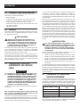
Table of Contents
WARNING!
California Proposition 65
Engine exhaust and some of its constituents are known to the state of California to cause cancer,
birth defects, and other reproductive harm.
WARNING!
California Proposition 65
This product contains or emits chemicals known to the state of California to cause cancer,
birth defects, and other reproductive harm.

1
After this heading, read instructions that, if not
strictly complied with, could result in serious
personal injury, including death.
After this heading, read instructions that, if not
strictly complied with, might result in minor or
moderate injury.
NOTE:
After this heading, read instructions that, if not strictly complied
with, may result in damage to equipment and/or property.
These safety warnings cannot eliminate the hazards that they
indicate. Common sense and strict compliance with the special
instructions while performing the service are essential to preventing
accidents.
Four commonly used safety symbols accompany the DANGER,
WARNING and CAUTION blocks. The type of information each indi-
cates follows:
This symbol points out important safety infor-
mation that, if not followed, could endanger
personal safety and/or property.
This symbol points out potential explosion
hazard.
This symbol points out potential fire hazard.
This symbol points out potential electrical
shock hazard.
GENERAL HAZARDS
• Any AC generator that is used for backup power if a NORMAL
(UTILITY) power source failure occurs, must be isolated from
the NORMAL (UTILITY) power source by means of an approved
transfer switch. Failure to properly isolate the NORMAL and
STANDBY power sources from each other may result in injury
or death to electric utility workers, due to backfeed of electrical
energy.
• Improper or unauthorized installation, operation, service or repair
of the equipment is extremely dangerous and may result in death,
serious personal injury, or damage to equipment and/or personal
property.
• Extremely high and dangerous power voltages are present
inside an installed transfer switch. Any contact with high voltage
terminals, contacts or wires will result in extremely hazardous,
and possibly LETHAL, electric shock. DO NOT WORK ON THE
TRANSFER SWITCH UNTIL ALL POWER VOLTAGE SUPPLIES
TO THE SWITCH HAVE BEEN POSITIVELY TURNED OFF.
• Competent, qualified personnel should install, operate and service
this equipment. Adhere strictly to local, state and national electri-
cal and building codes. When using this equipment, comply with
regulations the National Electrical Code (NEC), CSA Standard;
C22.1 Canadian Electric Code and Occupational Safety and
Health Administration (OSHA) have established.
• Never handle any kind of electrical device while standing in water,
while barefoot, or while hands or feet are wet. DANGEROUS
ELECTRICAL SHOCK MAY RESULT.
• Remove all jewelry (such as rings, watches, bracelets, etc.) before
working on this equipment.
• If work must be done on this equipment while standing on metal
or concrete, place insulative mats over a dry wood platform. Work
on this equipment only while standing on such insulative mats.
• Never work on this equipment while physically or mentally fatigued.
• Keep the transfer switch enclosure door closed and bolted at all
times. Only qualified personnel should be permitted access to the
switch interior.
• In case of an accident caused by electric shock, immediately
shut down the source of electrical power. If this is not possible,
attempt to free the victim from the live conductor but AVOID
DIRECT CONTACT WITH THE VICTIM. Use a nonconducting
implement, such as a dry rope or board, to free the victim from the
live conductor. If the victim is unconscious, apply first aid and get
immediate medical help.
• When an automatic transfer switch is installed for a standby gen-
erator set, the generator engine may crank and start at any time
without warning. To avoid possible injury that might be caused by
such sudden start-ups, the system’s automatic start circuit must
be disabled before working on or around the generator or transfer
switch. Then place a “DO NOT OPERATE” tag on the transfer
switch and on the generator. Remove the Negative (Neg) or (–)
battery cable.
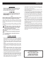
For authorized service,
reference the dealer locator
number found inside the
generator owner’s manual.
Safety Rules

2
1.1 INTRODUCTION
This manual has been prepared especially for the purpose of familiar-
izing personnel with the design, application, installation, operation
and servicing of the applicable equipment. Read the manual carefully
and comply with all instructions. This will help to prevent accidents or
damage to equipment that might otherwise be caused by careless-
ness, incorrect application or improper procedures.
Every effort has been expended to make sure that the contents of this
manual are both accurate and current. The manufacturer, however,
reserves the right to change, alter or otherwise improve the product
at any time without prior notice.
1.2 UNPACKING
Carefully unpack the transfer switch. Inspect closely for any damage
that might have occurred during shipment. The purchaser must file with
the carrier any claims for loss or damage incurred while in transit.
Check that all packing material is completely removed from the switch
prior to installation.
1.3 EQUIPMENT DESCRIPTION
The automatic transfer switch is used for transferring electrical
load from a UTILITY (NORMAL) power source to a GENERATOR
(STANDBY) power source. Such a transfer of electrical loads occurs
automatically when the UTILITY power source has failed or is sub-
stantially reduced and the GENERATOR source voltage and frequen-
cy have reached an acceptable level. The transfer switch prevents
electrical feedback between two different power sources (such as
the UTILITY and GENERATOR sources) and, for that reason, codes
require it in all standby electric system installations.
The transfer switch consists of a transfer mechanism, UTILITY SER-
VICE DISCONNECT circuit breaker, a relay control, fuses, terminal
strip, and fuse holder for connection of sensing wires.
This transfer switch is suitable for use as service equipment.
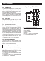
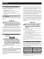
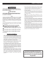
1.3.1 TRANSFER SWITCH MECHANISM
These switches (Figure 1.1) are used with a single-phase system,
when the single-phase NEUTRAL line is to be connected to a Neutral
Lug and is not to be switched.
Solderless, screw-type terminal lugs are standard.
Switch Rating Wire Range
300/400A (1) #4-600 MCM or
(2) 1/0-250 MCM
This transfer switch is suitable for control of motors, electric discharge
lamps, tungsten filament and electric heating equipment where the
sum of motor full load ampere ratings and the ampere ratings of other
loads do not exceed the ampere rating of the switch and the tungsten
load does not exceed 30 percent of the switch rating.
This UL listed transfer switch is for use in optional standby systems
only (NEC article 702).
This transfer switch is suitable for use on a circuit capable of 18,000
rms symmetrical amperes, 240 VAC maximum.
Figure 1.1 — Typical ATS Transfer Mechanism
1.3.2 UTILITY SERVICE CIRCUIT BREAKER
The utility service circuit breaker for the 300/400 amp models are:
• Generac, 300/400AF
• 120/240VAC, 300/400A
• 50/60 Hertz
• Wire range: (1) #4-600 MCM or (2) 1/0-250 MCM
• The conductor tightening torque is 375 in-lbs.
General Information

3
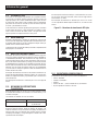
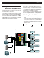
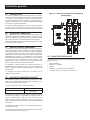
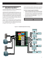
1.3.3 LOAD SHED MODULE (LSM)
The Overload Prevention Control Board is designed to prevent an
overload on the generator when it is supplying the customer loads.
See Figure 1.2. Up to six loads can be managed by the OPCB; 2 air
conditioner loads and 4 other loads. The OPCB manages the loads
by “shedding” the connected loads in the event of a drop in generator
frequency (overload). Loads to be “shed” are grouped in 4 priority
levels on the OPCB.
• Priority 1 and 2 has connections for both one air conditioner and
one contactor. Both an air conditioner and a contactor can be
used at the same time if desired. To control an air conditioner,
no additional equipment is required. Internal relays interrupt the
thermostat 24VAC control signal to disable the air conditioner load.
• Priority 3 and 4 have connections for one contactor only.
• Four LEDs, located on the Overload Prevention Control Board,
will indicate when a load priority level is enabled. When loads are
connected, the LEDs will be illuminated.
• Any loads, including central air conditioners, can be controlled
via a contactor that must be purchased separately. Up to four
contactors can be controlled by the Overload Prevention Control
Board. (The 24 VAC or 120 VAC is supplied through the OPCB to
energize each contactor coil).
• Generator overload condition is determined by generator frequen-
cy. Loads are shed when the frequency is <58Hz for 3 seconds or
<50Hz for ½ Second (for 60Hz).
The OPCB has a Test button which forces the unit to act as if an
overload has occurred. This button operates even when the transfer
signal is inactive.
Figure 1.2 — Overload Prevention Control Board
0 Ground
194 +12V
23 Transfer
T1
NEUTRAL
A/C 1
24V
A/C 2
24V
LOAD 1
LOAD 2
LOAD 3
LOAD
4
A/C 1 & LOAD 1
LOAD
SUPPLY
LOAD
SUPPLY
1
2
1
2
2
2
2
1
1
1
1A MAX
1A MAX
1A MAX
1A MAX
A/C 2 & LOAD 2
LOAD 3
LOAD 4
Air Conditioner Connections:
Up to two A/Cs can be
controlled here via their low
voltage thermostat wires
Status LEDs: Shows which
loads are currently allowed to
run
Load Connections: Up to four
loads of any type can be
controlled via these
connections. A separate
contactor module is required
2
2
1
2
1
2
1
2
2
1
1
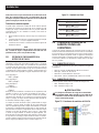
1.4 TRANSFER SWITCH DATA DECAL
A DATA DECAL is permanently affixed to the transfer switch enclo-
sure. Use this transfer switch only with the specific limits shown on
the DATA DECAL and on other decals and labels that may be affixed
to the switch. This will prevent damage to equipment and property.
When requesting information or ordering parts for this equipment, make
sure to include all information from the DATA DECAL.
Record the Model and Serial numbers in the space provided for future
reference.
MODEL #
SERIAL #
1.5 TRANSFER SWITCH ENCLOSURE
The standard switch enclosure is a National Electrical Manufacturer’s
Association (NEMA) and UL 3R type. UL and NEMA 3R type enclo-
sures primarily provide a degree of protection against falling rain and
sleet; undamaged by the formation of ice on the enclosure.
1.6 SAFE USE OF TRANSFER SWITCH
Before installing, operating or servicing this equipment, read the
SAFETY RULES (inside front cover) carefully. Comply strictly with all
SAFETY RULES to prevent accidents and/or damage to the equip-
ment. The manufacturer recommends that a copy of the SAFETY
RULES are posted near the transfer switch. Also, be sure to read all
instructions and information found on tags, labels and decals affixed
to the equipment.
Two publications that outline the safe use of transfer switches are
the following:
• NFPA 70; National Electrical Code
• NFPA 70E; Standard for Electrical Safety in the Workplace
• UL 1008, STANDARD FOR SAFETY-AUTOMATIC TRANSFER
SWITCHES
NOTE:
It is essential to use the latest version of any standard to ensure
correct and current information.
General Information

4
2.1 INTRODUCTION TO INSTALLATION
This equipment has been wired and tested at the factory. Installing the
switch includes the following procedures:
• Mounting the enclosure.
• Connecting power source and load leads.
• Connecting the generator sensing and transfer relay circuits.
• Connecting any auxiliary contact (if needed)
• Connect Overload Prevention Control Board loads (as required)
• Testing functions.
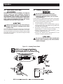
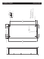
2.2 MOUNTING
Mounting dimensions for the transfer switch enclosure are in this
manual. Enclosures are typically wall-mounted. See “Installation
Diagram”.
Handle transfer switches carefully when
installing. Do not drop the switch. Protect the
switch against impact at all times, and against
construction grit and metal chips. Never install
a transfer switch that has been damaged.
This transfer switch is mounted in a UL type 3R enclosure. It can be
mounted outside or inside and should be based on the layout of instal-
lation, convenience and proximity to the utility supply and load center.
Install the transfer switch as close as possible to the electrical loads
that are to be connected to it. Mount the switch vertically to a rigid
supporting structure. To prevent switch distortion, level all mounting
points. If necessary, use washers behind mounting holes to level the
unit.
2.3 CONNECTING POWER SOURCE AND
LOAD LINES
Make sure to turn OFF both the UTILITY
(NORMAL) and GENERATOR ( STANDBY)
power supplies before trying to connect power
source and load lines to the transfer switch.
Supply voltages are extremely high and dan-
gerous. Contact with such high voltage power
supply lines causes extremely hazardous, pos-
sibly lethal, electrical shock.
Wiring diagrams and electrical schematics are provided in this
manual.
NOTE:
All installations must comply with national, state and local
codes. It is the responsibility of the installer to perform an instal-
lation that will pass the final electrical inspection.
The utility supply connection is made at the UTILITY SERVICE DIS-
CONNECT circuit breaker terminals. The generator and customer
load connections are made at the transfer switch mechanism, inside
the switch enclosure.
Conductor sizes must be adequate to handle the maximum current
to which they will be subjected, based on the 75°C column of tables,
charts, etc. used to size conductors. The installation must comply fully
with all applicable codes, standards and regulations.
All power cables must enter the enclosure through the knockouts
provided. If not using the knockouts, conduit entry into the enclo-
sure must be at or below knockouts to maintain the Type 3R rating.
Conduits should be arranged to provide separation between the Utility
and Generator supply conductors inside the enclosure.
Before connecting wiring cables to terminals, remove any surface
oxides from the cable ends with a wire brush. If not using the knock-
outs, entry must be at or below knockouts. If ALUMINUM conductors
are used, apply corrosion inhibitor to conductors. Tighten terminal
lugs to the torque values as noted on Utility Service Disconnect
Circuit Breaker, and on the decal located on the inside of the door.
After tightening terminal lugs, carefully wipe away any excess corro-
sion inhibitor.
Use a torque wrench to tighten the conductors,
being sure not to overtighten, or damage to
the switch base could occur. If not tightened
enough, a loose connection would result,
causing excess heat which could damage the
switch base.
Connect power source load conductors to clearly marked transfer
mechanism terminal lugs as follows:
1. Connect UTILITY (NORMAL) power source cables to UTILITY
SERVICE DISCONNECT circuit breaker.
2. Connect the GENERATOR (STANDBY) source power cables to
transfer switch terminals E1, E2.
3. Connect customer LOAD leads to switch terminals T1, T2.
Conductors must be properly supported, of approved insulative quali-
ties, protected by approved conduit, and of the correct wire gauge
size in accordance with applicable codes.
Be sure to maintain proper electrical clearance between live metal
parts and grounded metal. Allow at least 1/2 inch for 100-400 amp
circuits.
2.4 CONNECTING START CIRCUIT WIRES
Control system interconnections may consist of N1, N2, and T1, and
leads 0, 23 and 194. Reference instruction manual of specific engine
generator for wiring connection details. Recommended wire gauge
sizes for this wiring depends on the length of the wire, as recom-
mended in the following chart:
MAXIMUM WIRE LENGTH RECOMMENDED WIRE SIZE
1-115 ft (1-35m) No. 18 AWG.
116-185 ft (36-56m) No. 16 AWG.
186-295 ft (57-89m) No. 14 AWG.
296-460 ft (90-140m) No. 12 AWG.
Exceptions: If the insulation rating on all wiring is rated for 600V,
and the application meets code, it is acceptable to include generator
control and power wiring in one conduit.
Installation

5
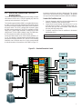
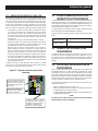
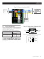
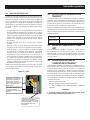
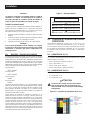
2.5 OVERLOAD PREVENTION CONTROL
BOARD (OPCB)
The OPCB can control an air conditioner (24 VAC) directly or a sepa-
rate contactor PPM (24 VAC or 120 VAC operating coil) which can
control any load connected to it. See Figure 2.1.
The Power Management Module (PMM) is not supplied with the trans-
fer switch. It can be purchased separately from the manufacturer for
use with the Overload Prevention Control Board (OPCB) mounted in
the transfer switch. The OPCB is designed and connected to power
the PMM contactor operating coil. The OPCB is supplied by a 24 VAC
supply, class 2 power supply transformer, connected to the LOAD
supply in the RTS. (Each output is limited to 1 amp) The PMM contac-
tor coil connections are made at the OPCB terminal strip.
Connect the PMM contactor coil to OPCB contactor terminals (1, 2,
3 or 4). The selection of contactor terminal used will depend on the
priority of the load being controlled. This is a 24 VAC circuit and wiring
methods for class 2 should be used. Use ¼” quick connect terminals
to make the contactor coil connections on the PMM. See Figure 2.1.
A grommet is provided to route Class 2 wiring through. The grommet
can be used in any knockout for NEMA 1 installations. The grommet
can only be used in the bottom knockouts for NEMA 3R installations.
Control of Air Conditioner Load
1. Route the thermostat cable (from the furnace/thermostat to the
outdoor air conditioner unit) to the transfer switch.
2. Connect the wire to the terminal strip terminals (Air 1) on the
OPCB as shown in Figure 2.1. These are normally closed con-
tacts which open upon load shed conditions. Route thermostat
wire away from High voltage wires.
3. If required, connect the second air conditioner to the terminal
strip terminals (Air 2).
Contact Ratings
Air 1 & 2 24 VAC, 5.0 Amps Max
Installation
Y wire
Y wire
0 Ground
194 +12V
23 Transfer
T1
NEUTRAL
A/C 1
24V
A/C 2
24V
LOAD 1
LOAD 2
LOAD 3
LOAD
4
A/C 1 & LOAD 1
PMM #1 Load #1
Supply
Coil wires
PMM #2 Load #2
Supply
PMM #4 Load #4
Supply
PMM #3 Load #3
Supply
LOAD
SUPPLY
LOAD
SUPPLY
1
2
1
2
2
2
2
1
1
1
1A MAX
1A MAX
1A MAX
1A MAX
A/C 2 & LOAD 2
LOAD 3
LOAD 4
Figure 2.1 — Overload Prevention Control

6
NOTE:
These instructions are for a typical air conditioner installation.
Control of heat pump and 2-stage air conditioners will require
special connections or the use of Power Management Modules
to control the loads.
Control of a Separate Contactor
A separate contactor relay module can be purchased from the manu-
facturer. This model is supplied in a 24 VAC (requires a starter kit,
which includes a field installed 24VAC transformer and the first 50
amp, 24V actuated module) or 120 VAC coil version.
1. Mount the contactor module and connect the load to the main
contacts.
2. Connect the contactor coil to the desired OPCB (contactor 1, 2,
3 or 4) terminals on the terminal strip.
3. Connect additional Power Management Module contactors in a
similar fashion.
NOTE:
It will be necessary to determine the order of “shedding” the
connected loads and connect the loads to the OPCB in that
order. One is the highest priority and four is the lowest priority.
2.5.1 LOAD SHED SEQUENCE OF OPERATION
When configured for full functionality, six loads are organized into
four priority groups. Priority 1 (A/C 1) and the associated general use
contactor (Load 1) is the highest priority and is usually the first load(s)
reconnected (except in fast load shed mode). Priority 4 (Load 4) is the
lowest priority and is usually the last load reconnected (except in fast
load shed mode). The priority groups are as follows:
Priority Group 1
• A/C 1 and Load 1
Priority Group 2
• A/C 2 and Load 2
Priority Group 3
• Load 3
Priority Group 4
• Load 4
Since A/C is typically considered the most important, it is hardwired as
the two highest priority levels (A/C 1, A/C 2). Two other loads that may
be considered of equivalent importance are wired to the associated
general use contactors (Load 1, Load 2). Loads of lesser importance
are wired to the remaining contactors (Load 3, Load 4).
If the OPCB is fully functional and managing six connected loads,
and an event occurs which causes a load to increase beyond the
capacity of the generator, the OPCB identifies an overload condition
and instantly sheds all loads. After five minutes elapses, the OPCB
reconnects the loads associated with Priority Group 1 (A/C 1, Load 1),
and then reconnects the remaining loads at fifteen second intervals.
If the OPCB sees another overload while it is reconnecting loads, the
offending load is shed and locked out for 30 minutes. The next load
in the sequence is then reconnected. This process continues until all
loads have tried to reconnect (Figure 2.4).
Figure 2.4 — Standard Load Shed
Overload Condition - All Loads Shed
5 Minutes Elapses - Priority Group 1 Reconnected
15 Seconds Elapses - Priority Group 2 Reconnected
15 Seconds Elapses - Priority Group 3 Reconnected
15 Seconds Elapses - Priority Group 4 Reconnected
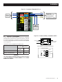
2.6 CONNECTION OF POWER SUPPLY FOR
CONTACTORS
The Overload Prevention Control Board (OPCB) can be powered from
either a 24 VAC or 120 VAC power supply. The 24 VAC supply is from
a class 2 transformer that can be purchased from the manufacturer.
Mounting holes are provided in the enclosure subplate for mounting of
the transformer. The 120 VAC supply is fused at 5 amps and is factory
connected to OPCB terminals labeled "T1 and "Neutral".
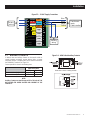
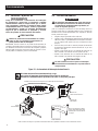
2.6.1 24 VAC SUPPLY
Transformer connection are made as shown in Figure 2.2 on page 7.
• Blue wire - OPCB "LOAD SUPPLY 1" terminal
• Black wire - OPCB "T1" terminal
• White wire - OPCB "NEUTRAL" terminal
• Yellow wire - OPCB "LOAD SUPPLY 2" terminal
2.6.2 120 VAC SUPPLY
Install the following jumpers on the OPCB module (Figure 2.3).
• Wire - Load Supply 1 to T1
• Wire - Load Supply 2 to T2
Load supply voltage on the OPCB terminals
must match the PMM contactor coil voltage, or
the equipment will be damaged.
Figure 2.3 — 120 VAC Supply Connections
Installation

Generac
®
Power Systems, Inc. 7
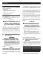
2.7 AUXILIARY CONTACTS
If desired, there are Auxiliary Contacts on the transfer switch to
operate customer accessories, remote advisory lights, or remote
annunciator devices. A suitable power source must be connected to
the COMMON (C) terminal. See Figure 2.4.
Contact operation is shown in the following chart:
Switch Position
Utility Standby
Common to Normally Open Open Closed
Common to Normally Closed Closed Open
NOTE:
Auxiliary Contacts are rated 10 amps at 125 or 250 volts AC. DO
NOT EXCEED THE RATED VOLTAGE AND CURRENT OF THE
CONTACTS.
Figure 2.4 – 400A Switch Auxiliary Contacts
Side views shown in Utility position
7
Installation
0 Ground
194 +12V
23 Transfer
T1
NEUTRAL
A/C 1
24V
A/C 2
24V
LOAD 1
LOAD 2
LOAD 3
LOAD
4
A/C 1 & LOAD 1
LOAD
SUPPLY
LOAD
SUPPLY
1
2
1
2
2
2
2
1
1
1
1A MAX
1A MAX
1A MAX
1A MAX
A/C 2 & LOAD 2
LOAD 3
LOAD 4
Blue
Black
White
Yellow
Factory
wiring
Tran sform er
leads
Field installed
Existing
wiring
Figure 2.2 — 24 VAC Supply Connections

8
3.1 FUNCTIONAL TESTS AND
ADJUSTMENTS
Following transfer switch installation and intercon-
nection, inspect the entire installation carefully. A
competent, qualified electrician should inspect it.
The installation should comply strictly with all appli-
cable codes, standards, and regulations. When abso-
lutely certain the installation is proper and correct,
complete a functional test of the system.
Perform functional tests in the exact order pre-
sented in this manual, or damage to the switch
could be done.
IMPORTANT: Before proceeding with functional tests, read and make
sure you understand all instructions and information in this section.
Also read the information and instructions of labels and decals affixed
to the switch. Note any options or accessories that might be installed
and review their operation.
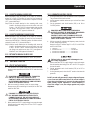
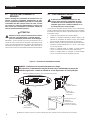
3.2 MANUAL OPERATION
Do NOT manually transfer under load.
Disconnect transfer switch from all power
sources by approved means, such as a main
circuit breaker(s).
A manual HANDLE is shipped with the transfer switch. Manual opera-
tion must be checked BEFORE the transfer switch is operated electri-
cally. To check manual operation, proceed as follows:
1. Ensure the generator is in the OFF mode.
2. Turn OFF or OPEN both UTILITY and EMERGENCY power sup-
plies to the transfer switch, with whatever means provided (such
as the main line circuit breakers).
3. Note position of transfer mechanism main contacts by observing
display windows in “A” and “B” in Figure 3.1 as follows:
• Window “A” ON, Window “B” OFF - LOAD terminals (T1, T2) are
connected to utility terminals (N1, N2).
• Window “A” OFF, Window “B” ON - LOAD terminals (T1, T2) are
connected to emergency terminals (E1, E2).
Do not use excessive force when operating the
transfer switch manually or the manual handle
could be damaged.
Operation
Figure 3.1 — Actuating Transfer Switch

9
3.2.1 CLOSE TO NORMAL SOURCE SIDE
Before proceeding, verify the position of the switch by observing
window “A” in Figure 3.1. If window “A” reads “ON”, the contacts are
closed in the normal position, no further action is required. If it reads
“OFF”, proceed with Step 1.
Step 1: With the handle attached to the actuating shaft, move
handle in the direction of the arrow on the switch cover until
it stops — DO NOT FORCE. Release handle slowly to allow
the spring in the switch box to relax. “ON” now appears in
Window “A” and “OFF” appears in Window “B”.
3.2.2 CLOSE TO EMERGENCY SOURCE SIDE
Before proceeding, verify the position of the switch by observing
window “B” in Figure 3.1. If window “B” reads “ON”, the contacts are
closed in the EMERGENCY (STANDBY) position. No further action is
required. If it reads “OFF”, proceed with Step 1.
Step 1: With the handle attached to the actuating shaft, move the
handle in the direction of the arrow on the switch cover until
it stops - DO NOT FORCE. Release handle slowly to allow
the spring in the switch box to relax. “OFF” now appears in
Window “A” and “ON” appears in Window “B”.
3.2.3 RETURN TO NORMAL SOURCE SIDE
Manually actuate switch to return Window “A” to the “ON” position.
3.3 VOLTAGE CHECKS
3.3.1 UTILITY VOLTAGE CHECKS
1. Turn ON the UTILITY power supply to the transfer switch with
whatever means provided (such as the UTILITY maim line circuit
breaker).
PROCEED WITH CAUTION. THE TRANSFER
SWITCH IS NOW ELECTRICALLY HOT.
CONTACT WITH LIVE TERMINALS RESULTS
IN EXTREMELY HAZARDOUS AND POSSIBLY
FATAL ELECTRICAL SHOCK.
2. With an accurate AC voltmeter, check for correct voltage.
Measure across ATS terminal lugs N1 and N2; N1 to NEUTRAL
and N2 to NEUTRAL.
FAILURE TO TURN OFF THE UTILITY SUP-
PLY BEFORE WORKING ON THE UTILITY
CONNECTIONS OF THE ATS WILL RESULT
IN EXTREMELY DANGEROUS AND POSSIBLY
FATAL ELECTRICAL SHOCK.
3. When certain that UTILITY supply voltage is correct and compat-
ible with transfer switch ratings, turn OFF the UTILITY supply to
the transfer switch.
3.3.2 GENERATOR VOLTAGE CHECKS
1. On the generator panel, select the MANUAL mode of operation.
The generator should crank and start.
2. Let the generator stabilize and warm up at no-load for at least
five minutes.
3. Set the generator's main circuit breaker (CB1) to its ON or
CLOSED position.
PROCEED WITH CAUTION. GENERATOR
OUTPUT VOLTAGE IS NOW BEING DELIVERED
TO TRANSFER SWITCH TERMINALS.
CONTACT WITH LIVE TERMINALS RESULTS
IN EXTREMELY DANGEROUS AND POSSIBLY
FATAL ELECTRICAL SHOCK.
4. With an accurate AC voltmeter and frequency meter, check the
no-load, voltage and frequency.
Measure across ATS terminal lugs E1 to E2; E1 to NEUTRAL
and E2 to NEUTRAL.
a. Frequency ..............................................60-62 Hz
b. Terminals E1 to E2 ................................240-246 VAC
c. Terminals E1 to NEUTRAL ....................120-123 VAC
d. Terminals E2 to NEUTRAL ....................120-123 VAC
Failure to do so may result in damage to cer-
tain rotary equipment.
5. When certain that UTILITY supply voltage is correct and compat-
ible with transfer switch ratings, turn OFF the UTILITY supply to
the transfer switch.
6. Set the generator’s main circuit breaker (CB1) to its OFF or
OPEN position.
7. On the generator panel, select the OFF mode to shut down the
generator.
NOTE:
Do NOT proceed until generator AC output voltage and frequen-
cy are correct and within stated limits. If the no-load voltage is
correct but no-load frequency is incorrect, the engine governed
speed probably requires adjustment. If no-load frequency is
correct but voltage is not, the voltage regulator may require
adjustment.
Operation

10
3.4 GENERATOR TESTS UNDER LOAD
1. Set the generator's main circuit breaker to its OFF or OPEN posi-
tion.
2. Manually actuate the transfer switch main contacts to their emer-
gency (Standby) position. Refer to “Manual Operation”.
3. To start the generator, select the MANUAL mode or operation.
When engine starts, let it stabilize for a few minutes.
4. Turn the generator's main circuit breaker to the ON or CLOSED
position. The generator now powers all LOAD circuits. Check
generator operation under load as follows:
• Turn ON electrical loads to the full rated wattage/amperage
capacity of the generator. DO NOT OVERLOAD.
• With maximum rated load applied, check voltage and frequency
across transfer switch terminals E1 and E2. Voltage should be
greater than 230 volts (240VAC system); frequency should be
greater than 59 Hz.
• Let the generator run under rated load for at least 30 minutes.
With unit running, listen for unusual noises, vibration, overheat-
ing, etc., that might indicate a problem.
5. When checkout under load is complete, set main circuit breaker
of the generator to the OFF or OPEN position.
6. Let the generator run at no-load for several minutes. Then, shut
down by selecting the OFF mode.
7. Move the switch's main contacts back to the UTILITY position.
For example, load connected to utility power supply. Refer to
“Manual Operation”. Handle and operating lever of transfer
switch should be in down position.
8. Turn on the utility power supply to transfer switch, using what-
ever means provided (such as a utility main line circuit breaker).
The utility power source now powers the loads.
9. Select the generator's OFF mode to shut down the generator.
The system is now set for fully automatic operation.
3.5 CHECKING AUTOMATIC OPERATION
To check the system for proper automatic operation, proceed as fol-
lows:
1. Ensure that the generator is in it’s OFF mode.
2. Install front cover of the transfer switch.
3. Turn ON the utility power supply to the transfer switch, using the
means provided (such as a utility main line circuit breaker).
NOTE:
Transfer Switch will transfer back to utility position.
4. Set the generator’s main circuit breaker to its ON (or CLOSED)
position.
5. On the generator panel, select the AUTO mode. The system is
now ready for automatic operation.
6. Turn OFF the utility power supply to the transfer switch.
With the generator ready for automatic operation, the engine should
crank and start when the utility source power is turned OFF after a
10 second delay (factory default setting). After starting, the transfer
switch should connect load circuits to the standby side after a five
(5) second delay. Let the system operate through its entire automatic
sequence of operation.
3.6 TESTING OVERLOAD PREVENTION
CONTROL BOARD (OPCB)
A Test push-button is provided on the bottom of the OPCB to test the
operation of the load shed functions. The Test button will work when
the ATS is in the Utility or the Generator position.
1. Turn the Utility supply on to the ATS.
2. Press the TEST push-button on the OPCB.
3. Verify that all of the connected loads to be “shed” become dis-
abled. The method of verification will depend on the type of load.
4. After five (5) minutes verify AC 1 and Load 1 are energized
Status LED AC 1 and Load 1 is ON.
5. After another 15 seconds, verify AC 2 and Load 2 are energized
Status LED AC 2 and Load 2 are ON.
6. After another 15 seconds, verify Load 3 is energized Status Load
3 is ON.
7. After another 15 seconds, verify Load 4 is energized Status Load
4 is ON.
3.7 INSTALLATION SUMMARY
1. Ensure that the installation has been properly performed as
outlined by the manufacturer and that it meets all applicable laws
and codes.
2. Test and confirm proper operation of the system as outlined in
the appropriate installation and owner’s manuals.
3. Educate the end-user on the proper operation, maintenance and
service call procedures.
3.8 SHUTTING THE GENERATOR DOWN
WHILE UNDER LOAD
Important! To turn the generator off during utility outages to
perform maintenance, or conserve fuel, follow these important
steps:
To turn the generator OFF (while running in AUTO and online):
1. Turn OFF (or OPEN) the main Utility disconnect.
2. Turn OFF (or OPEN) the Main Line Circuit Breaker (MLCB) on
the generator.
3. Turn the generator OFF.
To turn the generator back ON:
1. Put the generator back into AUTO and allow to start and warm-
up for a few minutes.
2. Turn ON (or CLOSE) the MLCB on the generator.
The system will now be operating in its automatic mode. The main
utility disconnect can be turned ON (or CLOSED), but to shut the unit
off, this complete process must be repeated.
Operation

11
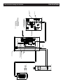
UTILITY
METER
SOCKET
GROUND BAR
NEUTRAL BAR
PANELBOARD
IN PANELBOARD
BONDING
CONNECTION
DISCONNECT
GROUND CONNECTION
A BONDING JUMPER IS PROVIDED
BETWEEN THE NEUTRAL LUG
AND ENCLOSURE AT THIS LOCATION
(FACTORY INSTALLED)
SERVICE DISCONNECT
ATS
TO GROUNDING
ELECTRODE
E1
N1
STANDBY
SUPPLY
E2
N2
UTILITY
SUPPLY
/NORMAL
0 GROUND
15B +12V
23 TRANSFER
AIR 1
AIR 2
PRIORITY 1
PRIORITY 2
PRIORITY 3
PRIORITY 4
T1
NEUTRAL
CONTACTOR
1
CONTACTOR
2
CONTACTOR
3
CONTACTOR
4
LOAD SHED
DEVICE
N1N1
23
194
TO TERMINAL NUMBERS
MATCH WIRE NUMBERS
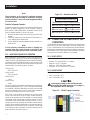
NOTE:
23
194
178
183
T1/LINE
ON
0
NEUT
T1
N2
E1
N2
NEU
E2
GROUND
CUSTOMER SUPPLIED
NEUTRAL WIRE
NEUTRAL BLOCK
CONNECTION PANEL
LIQUID-COOLED ENGINE GENERATOR
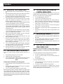
NOTES: 1. INSTALLATION MUST MEET
ALL NATIONAL, STATE AND
LOCAL ELECTRICAL CODES.
RESIDENTIAL/COMMERCIAL
2. REFERENCE INSTRUCTION MANUAL OF
SPECIFIC ENGINE GENERATOR FOR WIRING
CONNECTION DETAILS. THEY MAY DIFFER
FROM ILLUSTRATION.
T1
E2
E1
23
194
N2
N1
T2
A2
MANUAL OPERATION
DO NOT OPERATE WHILE THE SWITCH IS UNDER LOAD.
RATED VOLTAGE
TRANSFER SWITCH
RATED CURRENT
A1
M
CLOSE STANDBY
CLOSE UTILITY
600 VAC CSA
OFF
STANDBY
0D7294
XXXXXX
T1B2B1 T2
B
UTILITY
ON
480 VAC UL
400 AMP
SET MANUAL HANDLE ON "M" AND
SET MANUAL HANDLE ON "M" AND
OPERATE IN THE DIRECTION
OPERATE IN THE DIRECTION
A
LINE
PUSH TO TRIP
LOAD
0
N1
N2
T1
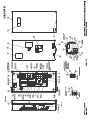
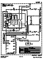
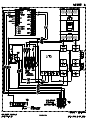
Interconnection Drawing No. 0K2429-B Electrical Data

12
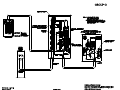
Installation Diagram Drawing No. 0K2438-A
424.0mm [16.69"]62.0mm [2.44"]
63.0mm [2.48"]
1090.0mm [42.91"]
1219.3mm [48.00"]
554.3mm [21.82"]
255.5mm [10.06"]
PADLOCK
(CUSTOMER SUPPLIED)
LOCATION
571.5mm [22.50"]
NOTE:
FOR 3R RATINGS CONDUITS MUST
ENTER BELOW ENERGIZED COMPONENTS
FOR FURTHER DETAILS SEE
INTERCONNECTION DIAGRAM IN THIS MANUAL.
268.35mm [10.56"]
ĵ14mm [ĵ0.6"]
ĵ8mm [ĵ0.3"]
7.48mm [0.3"]
4.02mm [0.2"]

13
Notes

Part No. 0K2014 Revision D (09/03/14) Printed in U.S.A.
© Generac Power Systems, Inc. All rights reserved
Specifications are subject to change without notice.
No reproduction allowed in any form without prior written consent from
Generac Power Systems, Inc.
Generac Power Systems, Inc.
S45 W29290 Hwy. 59
Waukesha, WI 53189
1-888-GENERAC (1-888-436-3722)
generac.com

15
Este manual debe permanecer con la unidad.
Manual del propietario
Interruptor automático de transferencia (ATS)
SE monofásico de 300/400 A
CONSULTE TODA LA DOCUMENTACIÓN APROPIADA.

Reglas de seguridad ..................................................................................16
Información general ...................................................................................18
1.1 Introducción ......................................................................................................18
1.2 Desembalaje ....................................................................................................18
1.3 Descripción del equipo .....................................................................................18
1.4 Etiqueta adhesiva de datos del interruptor de transferencia ...........................19
1.5 Gabinete del interruptor de transferencia ........................................................19
1.6 Uso seguro del interruptor de transferencia ....................................................19
Instalación ................................................................................................... 20
2.1 Introducción a la instalación .............................................................................20
2.2 Montaje ............................................................................................................20
2.3 Conexión de la alimentación y las líneas de carga .........................................20
2.4 Conexión de los cables del circuito de arranque .............................................20
2.5 Tarjeta de control de prevención de sobrecarga (OPCB) ................................21
2.6 Conexión de suministro de alimentación para los contactores .......................22
2.7 Contactos auxiliares .........................................................................................23
Funcionamiento .......................................................................................... 24
3.1 Pruebas y ajustes de funcionamiento ..............................................................24
3.2 Operación manual ............................................................................................24
3.3 Comprobaciones de voltaje .............................................................................25
3.4 Pruebas del generador bajo carga ..................................................................26
3.5 Comprobación del funcionamiento automático ................................................26
3.6 Prueba de la tarjeta de control de prevención de sobrecarga (OPCB) ...........26
3.7 Resumen de la instalación ...............................................................................26
3.8 Parada del generador mientras está bajo carga .............................................26
Notas ............................................................................................................27
REGLAS DE SEGURIDAD
¡GUARDE ESTAS INSTRUCCIONES! Lea la siguiente
información cuidadosamente antes de intentar insta-
lar, operar o dar servicio a este equipo. También lea
las instrucciones y la información de las etiquetas,
etiquetas adhesivas, y rótulos que pueden estar
fijadas en el interruptor de transferencia. Sustituya
cualquier etiqueta adhesiva o rótulo no sea más leg-
ible.
¡PELIGRO! La conexión de un generador a un siste-
ma eléctrico normalmente alimentado con el servicio
público debe ser realizada mediante equipamiento de
transferencia adecuado para aislar al sistema eléc-
trico del sistema de distribución de servicio público
cuando el generador está funcionando (Artículo
701 Sistemas de reserva requeridos legalmente o
artículo 702 Sistemas de reserva opcionales, según
corresponda). No aislar el sistema eléctrico mediante
estos medios puede ocasionar daños al generador
y también puede provocar lesiones o la muerte a
los trabajadores del servicio público de electricidad
debido a la realimentación de energía eléctrica.
El fabricante no puede prever todas las circunstancias posibles que podrían
involucrar un peligro. Las advertencias de este manual y los rótulos y eti-
quetas adhesivas fijadas en la unidad, por lo tanto, no son exhaustivas. Si
usa un procedimiento, método de trabajo o técnica de funcionamiento que
el fabricante no recomienda específicamente, asegúrese de que sea seguro
para otras personas. Asegúrese también de que el procedimiento, método de
trabajo o técnica de funcionamiento elegido no vuelvan inseguro al interruptor
de transferencia.
En toda esta publicación, en los rótulos y en las etiquetas adhesivas fijadas
en el generador, los bloques de PELIGRO, ADVERTENCIA, PRECAUCIÓN
y NOTA se usan para alertar al personal sobre instrucciones especiales
acerca de una operación en particular que puede ser peligrosa si se efectúa
de manera incorrecta o imprudente. Obsérvelos cuidadosamente. Sus defini-
ciones son las siguientes:
¡PELIGRO!
Luego de este encabezado, lea las instrucciones que,
si no se cumplen estrictamente, resultarán en lesiones
graves, incluso la muerte.
ADVERTENCIA!
Proposición 65 de California
El escape del motor y algunos de sus componentes son conocidos pore el Estado de California como
causa de cáncer, defectos congénitos y otros daños reproductivos.
ADVERTENCIA!
Proposición 65 de California
Este producto contiene o emite sustancias químicas que son conocidas por el Estado de California como
causa de cáncer, defectos congénitos y otros daños reproductivos.
16
Índice

17
¡ADVERTENCIA!
Luego de este encabezado, lea las instrucciones que, si
no se cumplen estrictamente, pueden resultar en lesiones
graves, incluso la muerte.
¡PRECAUCIÓN!
Luego de este encabezado, lea las instrucciones que, si
no se cumplen estrictamente, podrían resultar en lesio-
nes menores o moderadas.
NOTA:
Luego de este encabezado, lea las instrucciones que, si no se cumplen
estrictamente, pueden resultar en daños al equipo y/o a la propiedad.
Estas advertencias de seguridad no pueden eliminar los peligros que indican.
El sentido común y el cumplimiento estricto de las instrucciones especiales
mientras se desarrolla el servicio son esenciales para la prevención de
accidentes.
Cuatro símbolos de seguridad de uso común acompañan a los bloques de
PELIGRO, ADVERTENCIA y PRECAUCIÓN. Cada uno indica el siguiente
tipo de información:
Este símbolo señala información de seguridad
importante que, si no se respeta, podría poner en
peligro la seguridad personal y/o material.
Este símbolo señala un posible peligro de explosión.
Este símbolo señala un posible peligro de incendio.
Este símbolo señala un posible peligro de choque
eléctrico.
PELIGROS GENERALES
• Cualquier generador de CA que se use para alimentación de respaldo si
ocurre un fallo de la fuente de alimentación NORMAL (SERVICIO PÚBLI-
CO), debe ser aislado de la fuente de alimentación NORMAL (SERVICIO
PÚBLICO) mediante un interruptor de transferencia aprobado. No aislar
apropiadamente las fuentes de alimentación NORMAL y de RESERVA
entre sí puede ocasionar lesiones o la muerte a los trabajadores de la red
eléctrica debido a la realimentación de energía eléctrica.
• La instalación, operación, servicio o reparación incorrectos o no autor-
izados son extremadamente peligrosos y pueden ocasionar la muerte,
lesiones graves, o daño al equipo y/o a la propiedad personal.
• En el interruptor de transferencia instalado existen voltajes de alimen-
tación extremadamente altos y peligrosos. Cualquier contacto con ter-
minales, contactos o cables de alto voltaje resultará en choque eléctrico
extremadamente peligroso y posiblemente MORTAL. NO TRABAJE EN
EL INTERRUPTOR DE TRANSFERENCIA HASTA QUE TODOS LAS
SUMINISTROS DE ALIMENTACIÓN AL INTERRUPTOR HAYAN SIDO
EFECTIVAMENTE COLOCADOS EN OFF.
• La instalación, operación y servicio de este equipo deben ser realizados
por personal competente y calificado. Observe estrictamente los códigos
eléctrico y de construcción locales, estatales y nacionales. Al usar este
equipo, cumpla con la reglamentación del Código Eléctrico Nacional de
EE. UU. (NEC) y la norma CSA;C22.1 El Código Eléctrico Canadiense
y la Administración de Seguridad y Salud Ocupacional (OSHA) han
establecido:
• Nunca maneje ningún tipo de dispositivo eléctrico mientras esté parado
sobre agua, esté descalzo o cuando tenga las manos o los pies mojados.
PUEDE PRODUCIRSE UN CHOQUE ELÉCTRICO PELIGROSO.
• Quítese todas las alhajas (como anillos, relojes, brazaletes, etc.) antes de
trabajar en este equipo.
• Si se debe realizar trabajo en este equipo mientras esté parado sobre
metal o concreto, coloque alfombras aislantes sobre una plataforma de
madera seca. Trabaje en este equipo solo mientras esté parado sobre
esas alfombras aislantes.
• Nunca trabaje en este equipo mientras esté fatigado física o mental-
mente.
• Mantenga la puerta del gabinete del interruptor de transferencia cerrada
y empernada en todo momento. Solo debe permitirse el acceso al interior
del interruptor a personal calificado.
• En caso de un accidente causado por choque eléctrico, apague de inme-
diato la fuente de alimentación eléctrica. Si esto no es posible, intente
liberar a la víctima del conductor alimentado pero EVITE EL CONTACTO
DIRECTO CON LA VÍCTIMA. Use un implemento no conductor, como
una cuerda o tabla seca, para liberar a la víctima del conductor alimen-
tado. Si la víctima está inconsciente, aplique primeros auxilios y obtenga
ayuda médica de inmediato.
• Al instalar un interruptor de transferencia automático en un conjunto de
generador de reserva, el motor del generador puede efectuar giro de
arranque y arrancar en cualquier momento sin aviso. Para evitar posibles
lesiones que puedan ser causadas por tales arranques, el sistema de
arranque automático del sistema debe ser deshabilitado antes de trabajar
en o alrededor del generador o interruptor de transferencia. Luego colo-
que el rótulo "NO ACCIONAR" en el interruptor de transferencia y en el
generador. Retire el cable negativo (Neg) o (-) de la batería.
Para servicio autorizado, consulte con el
número de ubicación de concesionarios que
se encuentra dentro del manual del propietario
del generador.
Reglas de seguridad

18
1.1 INTRODUCCIÓN
Este manual ha sido preparado especialmente con el propósito de familiari-
zar al personal con el diseño, aplicación, instalación, operación y servicio del
equipo que aplique. Lea el manual cuidadosamente para cumplir con todas
las instrucciones. Esto ayudará a evitar accidentes o daños al equipamiento
que pueden de otra forma ser causados por falta de atención, aplicación
incorrecta, o procedimientos incorrectos.
Se han hecho todos los esfuerzos posibles para asegurar que los contenidos
de este manual sean precisos y estén actualizados. Sin embargo, el fabri-
cante se reserva el derecho de cambiar, alterar o de alguna otra manera
mejorar el producto en cualquier momento sin aviso previo.
1.2 DESEMBALAJE
Desembale cuidadosamente el interruptor de transferencia. Inspeccione de
cerca en busca de cualquier daño que pueda haber ocurrido durante el envío.
El comprador debe informar por escrito al transportista cualquier reclamo por
pérdidas o daños ocurridos durante el tránsito.
Compruebe que todo el material de embalaje sea retirado completamente del
interruptor previo a la instalación.
1.3 DESCRIPCIÓN DEL EQUIPO
El interruptor de transferencia automático se usa para transferir cargas eléc-
tricas de una fuente de alimentación del SERVICIO PÚBLICO (NORMAL) a
un GENERADOR (RESERVA). Dicha transferencia de cargas eléctricas se
produce automáticamente cuando la fuente del SERVICIO PÚBLICO ha fal-
lado o se ha reducido sustancialmente y el voltaje y la frecuencia de la fuente
de GENERADOR han alcanzado un nivel aceptable. El interruptor de trans-
ferencia impide la realimentación eléctrica entre dos fuentes de alimentación
diferentes (como las fuentes de SERVICIO PÚBLICO y de GENERADOR)
y, por ese motivo, los códigos lo requieren en todas las instalaciones de los
sistemas eléctricos de reserva.
El interruptor de transferencia consta de un mecanismo de transferencia, un
disyuntor de DESCONEXIÓN DEL SERVICIO PÚBLICO, un control de relés,
fusibles, una regleta de terminales y un portafusibles para la conexión de los
cables de detección.
Este interruptor de transferencia es adecuado para el uso como equipo de
servicio.
1.3.1 MECANISMO DEL INTERRUPTOR DE
TRANSFERENCIA
Estos interruptores (Figura 1.1) se usan con un sistema monofásico, donde
la línea NEUTRA monofásica será conectada a un terminal neutro y no se
conectará al interruptor.
Los terminales sin soldadura, de rosca son estándar.
Capacidad nominal del interruptor Intervalo del cable
300/400 A (1) Núm. 4-600 MCM o
(2) 1/0-250 MCM
Este interruptor de transferencia es adecuado para controlar motores,
lámparas de descarga eléctrica, equipos de filamento de tungsteno y de
calefacción eléctrica en los que la suma de los amperajes nominales de los
motores a plena carga y los amperajes de las restantes cargas no exceden
el amperaje del interruptor y la carga de tungsteno no excede el 30 % de la
capacidad nominal del interruptor.
Este interruptor de transferencia listado por UL está destinado al uso en siste-
mas de reserva opcionales únicamente (artículo 702 del Código Eléctrico
Nacional de EE. UU.- NEC).
Este interruptor de transferencia es adecuado para el uso en un circuito
con una capacidad de 18.000 amperios simétricos rms, con 240 VCA como
máximo.
Figura 1.1 - Mecanismo de transferencia ATS típico
1.3.2 DISYUNTOR DEL SERVICIO PÚBLICO
El disyuntor del servicio público para los modelos de 300/400 A es:
• Generac, 300/400AF
• 120/240 VCA, 300/400 A
• 50/60 Hz
• Intervalo del cable: (1) Núm. 4-600 MCM o (2) 1/0-250 MCM
• El par de apriete del conductor es 375 in-lb.
Información general
Page is loading ...
Page is loading ...
Page is loading ...
Page is loading ...
Page is loading ...
Page is loading ...
Page is loading ...
Page is loading ...
Page is loading ...
Page is loading ...
Page is loading ...
Page is loading ...
Page is loading ...
Page is loading ...
Page is loading ...
Page is loading ...
Page is loading ...
Page is loading ...
Page is loading ...
Page is loading ...
Page is loading ...
Page is loading ...
Page is loading ...
Page is loading ...
Page is loading ...
Page is loading ...
Page is loading ...
Page is loading ...
Page is loading ...
Page is loading ...
Page is loading ...
Page is loading ...
Page is loading ...
Page is loading ...
Page is loading ...
-
 1
1
-
 2
2
-
 3
3
-
 4
4
-
 5
5
-
 6
6
-
 7
7
-
 8
8
-
 9
9
-
 10
10
-
 11
11
-
 12
12
-
 13
13
-
 14
14
-
 15
15
-
 16
16
-
 17
17
-
 18
18
-
 19
19
-
 20
20
-
 21
21
-
 22
22
-
 23
23
-
 24
24
-
 25
25
-
 26
26
-
 27
27
-
 28
28
-
 29
29
-
 30
30
-
 31
31
-
 32
32
-
 33
33
-
 34
34
-
 35
35
-
 36
36
-
 37
37
-
 38
38
-
 39
39
-
 40
40
-
 41
41
-
 42
42
-
 43
43
-
 44
44
-
 45
45
-
 46
46
-
 47
47
-
 48
48
-
 49
49
-
 50
50
-
 51
51
-
 52
52
-
 53
53
-
 54
54
-
 55
55


Generac Sync, Service Rated, 400A RTSG400A3 User manual
- Type
- User manual
Ask a question and I''ll find the answer in the document
Finding information in a document is now easier with AI
in other languages
Other documents
-
Schneider Electric QO200WXBR Power Box Kit User manual
-
Amprobe PMM-C AC Current Transducer User manual
-
 MERLIN GERIN CDS Owner's manual
-
 MERLIN GERIN CDS TRI Owner's manual
-
Hubbell Wiring Device-Kellems PD1330 Installation guide
-
Square D 9422CMP50 User manual
-
-
Generac Power Systems 6297 Installation and Operating Instructions
-
Emerson Process Management T100-25C2 User manual
-

