Comfort Glow RFN28TC Owner's manual
- Category
- Space heaters
- Type
- Owner's manual

Save this manual for future reference.
®
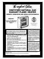
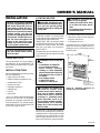
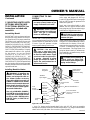
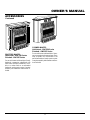
VENT-FREE NATURAL GAS
RADIANT FLAME
®
HEATER
OWNER’S OPERATION AND INSTALLATION MANUAL
14,000 to 28,000 Btu/Hr
with Thermostat "C"
Model
Shown with Optional
Mantel featuring
Built-in Base
WARNING: If the information in this manual is
not followed exactly, a fire or explosion may
result causing property damage, personal in-
jury, or loss of life.
— Do not store or use gasoline or other
flammable vapors and liquids in the vicinity of
this or any other appliance.
— WHAT TO DO IF YOU SMELL GAS
• Do not try to light any appliance.
• Do not touch any electrical switch; do not use
any phone in your building.
• Immediately call your gas supplier from a
neighbor’s phone. Follow the gas supplier’s
instructions.
• If you cannot reach your gas supplier, call the
fire department.
— Installation and service must be performed by a
qualified installer, service agency, or the gas
supplier.
WARNING: Improper installa-
tion, adjustment, alteration,
service, or maintenance can
cause injury or property dam-
age. Refer to this manual for
correct installation and op-
erational procedures. Fore
assistance or additional in-
formation consult a qualified
installer, service agency, or
the gas supplier.
RFN28TC
This appliance may be installed in an aftermarket* manufactured (mobile) home, where not prohibited by
state or local codes.
* Aftermarket: Completion of sale, not for purpose of resale, from the manufacturer
WARNING: This is an
unvented gas-fired heater. It
uses air (oxygen) from the
room in which it is installed.
Provisions for adequate com-
bustion and ventilation must
be provided. Refer to
Air for
Combustion and Ventilation
,
page 6 of this manual.

2
103508
VENT-FREE NATURAL GAS RADIANT
®
FLAME HEATER
1. This appliance is only for use with the
type of gas indicated on the rating plate.
This appliance is not convertible for use
with other gases.
2. Use only natural gas. Do not convert
heater to use different fuel type.
3. If you smell gas
• shut off gas supply
• do not try to light any appliance
• do not touch any electrical switch; do
not use any phone in your building.
• immediately call your gas supplier
from a neighbor’s phone. Follow the
gas supplier’s instructions
• if you cannot reach your gas supplier,
call the fire department
4. This heater shall not be installed in a
bedroom or bathroom.
5. Never install the heater
• in a recreational vehicle
• where curtains, furniture, clothing, or
other flammable objects are less than
36 inches from the front, top, or sides
of the heater
• as a fireplace insert
• in high traffic areas
• in windy or drafty areas
6. This heater needs fresh, outside air ven-
tilation to run properly. This heater has
an oxygen depletion sensor (ODS) pi-
lot light safety system. The ODS shuts
down the heater if not enough fresh air
is available. See Air for Combustion
and Ventilation, pages 6 through 8.
7. If heater shuts off, do not relight until
you provide fresh, outside air. If heater
keeps shutting off, have it serviced.
8. Do not run heater
• where flammable liquids or vapors
are used or stored.
• under dusty conditions.
9. Never place any objects on the heater.
10. Surface of heater becomes very hot
when running heater. Keep children and
adults away from hot surface to avoid
burns or clothing ignition. Heater will
remain hot for a time after shutdown.
Allow surface to cool before touching.
11. Carefully supervise young children
when they are in same room with
heater.
SAFETY
INFORMATION
WARNINGS
IMPORTANT: Read this owner’s
manual carefully and completely
before trying to assemble, oper-
ate, or service this heater. Im-
proper use of this heater can
cause serious injury or death from
burns, fire, explosion, electrical
shock, and carbon monoxide
poisoning.
DANGER: Carbon monoxide
poisoning may lead to death!
Carbon Monoxide Poisoning: Early
signs of carbon monoxide poisoning re-
semble the flu, with headaches, dizziness,
or nausea. If you have these signs, the heater
may not be working properly. Get fresh air
at once! Have heater serviced. Some people
are more affected by carbon monoxide than
others. These include pregnant women,
people with heart or lung disease or anemia,
those under the influence of alcohol, and
those at high altitudes.
Natural Gas: Natural gas is odorless. An
odor-making agent is added to natural gas.
The odor helps you detect a natural gas leak.
However, the odor added to natural gas can
fade. Natural gas may be present even though
no odor exists.
Make certain you read and understand all
warnings. Keep this manual for reference. It
is your guide to safe and proper operation of
this heater.
WARNING: Any change to this
heater or its controls can be
dangerous.
12. Make sure screen is in place before run-
ning heater.
13. Before using furniture polish, wax, car-
pet cleaner, or similar products, turn
heater off. If heated, the vapors from
these products may create a white pow-
der residue within burner box or on
adjacent walls or furniture.
14. Do not use heater if any part has been
under water. Immediately call a quali-
fied service technician to inspect the
room heater and to replace any part of
the control system and any gas control
which has been under water.
15. Turn off and unplug heater and let cool
before servicing. Only a qualified ser-
vice person should service and repair
heater.
16. Operating heater above elevations of
4,500 feet may cause pilot outage.
WARNING: Do not use a
blower insert, heat exchanger
insert, or other accessory not
approved for use with this heater.

3
103508
OWNER’S MANUAL
ASDFKIGLFJI alskdidkoemkgo dkirlnfgpd'fASDFKIGLFJI alskdidkoemkgo dkirlnfgpd'f
ASDFKIGLFJI alskdidkoemkgo dkirlnfgpd'fASDFKIGLFJI alskdidkoemkgo dkirlnfgpd'f
ASDFKIGLFJI alskdidkoemkgo dkirlnfgpd'fASDFKIGLFJI alskdidkoemkgo dkirlnfgpd'f
ASDFKIGLFJI alskdidkoemkgo dkirlnfgpd'fASDFKIGLFJI alskdidkoemkgo dkirlnfgpd'f
ASDFKIGLFJI alskdidkoemkgo dkirlnfgpd'fASDFKIGLFJI alskdidkoemkgo dkirlnfgpd'f
ASDFKIGLFJI alskdidkoemkgo dkirlnfgpd'fASDFKIGLFJI alskdidkoemkgo dkirlnfgpd'f
ASDFKIGLFJI alskdidkoemkgo dkirlnfgpd'fASDFKIGLFJI alskdidkoemkgo dkirlnfgpd'f
ASDFKIGLFJI alskdidkoemkgo dkirlnfgpd'fASDFKIGLFJI alskdidkoemkgo dkirlnfgpd'f
ASDFKIGLFJI alskdidkoemkgo dkirlnfgpd'ASDFKIGLFJI alskdidkoemkgo dkirlnfgpd'f
ASDFKIGLFJI alskdidkoemkgo dkirlnfgpd'fASDFKIGLFJI alskdidkoemkgo dkirlnfgpd'f
ASDFKIGLFJI alskdidkoemkgo dkirlnfgpd'fASDFKIGLFJI alskdidkoemkgo dkirlnfgpd'f
ASDFKIGLFJI alskdidkoemkgo dkirlnfgpd'fASDFKIGLFJI alskdidkoemkgo dkirlnfgpd'f
SDFKIGLFJI alskdidkoemkgo dkirlnfgpd'fASDFKIGLFJI alskdidkoemkgo dkirlnfgpd'f
ASDFKIGLFJI alskdidkoemkgo dkirlnfgpd'fASDFKIGLFJI alskdidkoemkgo dkirlnfgpd'f
ASDFKIGLFJI alskdidkoemkgo dkirlnfgpd'ASDFKIGLFJI alskdidkoemkgo dkirlnfgpd'f
ASDFKIGLFJI alskdidkoemkgo dkirlnfgpd'fASDFKIGLFJI alskdidkoemkgo dkirlnfgpd'f
ASDFKIGLFJI alskdidkoemkgo dkirlnfgpd'fASDFKIGLFJI alskdidkoemkgo dkirlnfgpd'f
ASDFKIGLFJI alskdidkoemkgo dkirlnfgpd'fASDFKIGLFJI alskdidkoemkgo dkirlnfgpd'f
ASDFKIGLFJI alskdidkoemkgo dkirlnfgpd'fASDFKIGLFJI alskdidkoemkgo dkirlnfgpd'f
ASDFKIGLFJI alskdidkoemkgo dkirlnfgpd'fASDFKIGLFJI alskdidkoemkgo dkirlnfgpd'f
ASDFKIGLFJI alskdidkoemkgo dkirlnfgpd'fASDFKIGLFJI alskdidkoemkgo dkirlnfgpd'f
ASDFKIGLFJI alskdidkoemkgo dkirlnfgpd'fASDFKIGLFJI alskdidkoemkgo dkirlnfgpd'f
ASDFKIGLFJI alskdidkoemkgo dkirlnfgpd'fASDFKIGLFJI alskdidkoemkgo dkirlnfgpd'f
ASDFKIGLFJI alskdidkoemkgo dkirlnfgpd'fASDFKIGLFJI alskdidkoemkgo dkirlnfgpd'f
ASDFKIGLFJI alskdidkoemkgo dkirlnfgpd'fASDFKIGLFJI alskdidkoemkgo dkirlnfgpd'f
ASDFKIGLFJI alskdidkoemkgo dkirlnfgpd'fASDFKIGLFJI alskdidkoemkgo dkirlnfgpd'f
ASDFKIGLFJI alskdidkoemkgo dkirlnfgpd'ASDFKIGLFJI alskdidkoemkgo dkirlnfgpd'f
ASDFKIGLFJI alskdidkoemkgo dkirlnfgpd'fASDFKIGLFJI alskdidkoemkgo dkirlnfgpd'f
ASDFKIGLFJI alskdidkoemkgo dkirlnfgpd'fASDFKIGLFJI alskdidkoemkgo dkirlnfgpd'f
ASDFKIGLFJI alskdidkoemkgo dkirlnfgpd'fASDFKIGLFJI alskdidkoemkgo dkirlnfgpd'f
SDFKIGLFJI alskdidkoemkgo dkirlnfgpd'fASDFKIGLFJI alskdidkoemkgo dkirlnfgpd'f
ASDFKIGLFJI alskdidkoemkgo dkirlnfgpd'fASDFKIGLFJI alskdidkoemkgo dkirlnfgpd'f
ASDFKIGLFJI alskdidkoemkgo dkirlnfgpd'ASDFKIGLFJI alskdidkoemkgo dkirlnfgpd'f
ASDFKIGLFJI alskdidkoemkgo dkirlnfgpd'fASDFKIGLFJI alskdidkoemkgo dkirlnfgpd'f
ASDFKIGLFJI alskdidkoemkgo dkirlnfgpd'fASDFKIGLFJI alskdidkoemkgo dkirlnfgpd'f
ASDFKIGLFJI alskdidkoemkgo dkirlnfgpd'fASDFKIGLFJI alskdidkoemkgo dkirlnfgpd'f
PRODUCT
IDENTIFICATION
LOCAL CODES
Install and use heater with care. Follow all
local codes. In the absence of local codes, use
the latest edition of The National Fuel Gas
Code ANS Z223, also known as NFPA 54*.
*Available from:
American National Standards Institute, Inc.
1430 Broadway
New York, NY 10018
National Fire Protection Association, Inc.
Batterymarch Park
Quincy, MA 02269
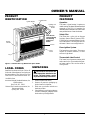
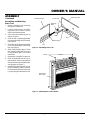
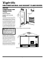
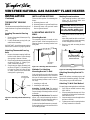
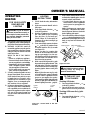
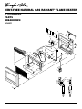
Figure 1 - Vent-Free Gas Log Natural Gas Space Heater
Ignitor Button
Screen
Front
Panel
Log
Lighting and
Warning
Plates
UNPACKING
1. Remove heater from carton.
2. Remove all protective packaging ap-
plied to heater for shipment.
3. Make sure your heater includes two
hardware packets.
4. Check heater for any shipping damage.
If heater is damaged, promptly inform
dealer where you bought heater.
PRODUCT
FEATURES
Operation
This heater is clean burning. It requires no
outside venting. This heater has been tested and
approved to ANS Z21.11.2 standard for
unvented heaters. State and local codes in some
areas prohibit the use of vent-free heaters.
Safety Pilot
This heater has a pilot with an Oxygen
Depletion Sensor Shutoff System (ODS).
The ODS/pilot is a required feature for vent-
free room heaters. The ODS/pilot shuts off
the heater if there is not enough fresh air.
Piezo Ignition System
This heater has a piezo ignitor. This system
requires no matches, batteries, or other
sources to light heater.
Thermostatic Heat Control
This heater has a thermostat sensing bulb
and a control valve. This results in the great-
est heater comfort. This can also result in
lower gas bills.
Control Knob
Heater
Cabinet
Note:
Do not
remove lighting
and warning
plates from
heater.
CAUTION: Do not remove the
metal data plates attached to the
heater. The data plates contain
important warranty information.

4
103508
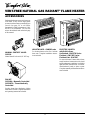
VENT-FREE NATURAL GAS RADIANT
®
FLAME HEATER
Truss-Head
Screw
WARNING: Always have
burner shield and screen in place
before operating heater. This pre-
vents excessive temperatures on
heater surfaces.
Failure to position the parts in
accordance with these diagrams
or failure to use only parts spe-
cifically approved with this heater
may result in property damage or
personal injury.
Attaching Brass Front Trim to
Front Panel
1. Locate brass front trim in brass trim
package.
2. Slide the head of two truss-head screws
from hardware packet into each end of
brass front trim (see Figure 5).
3. Line up screws with holes in front panel
(see Figure 4). Insert screws in holes.
Attach nuts from inside of front panel.
Tighten with wrench.
Nut
Front
Panel
Figure 5 - Attaching Brass Front Trim to
Front Panel
Brass Front
Trim
ASSEMBLY
ASSEMBLING HEATER
Tools Required:
• Phillips screwdriver
• 5/16" hex wrench
• Slotted screwdriver
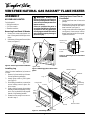
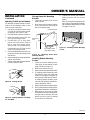
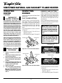
Removing Front Panel Of Heater
1. Remove two screws near bottom cor-
ners of front panel with Phillips screw-
driver.
2. Pull bottom of front panel forward, then
down (see Figure 2) .
Figure 2 - Removing Front Panel of Heater
Figure 3 - Attaching Ignitor Cable to Piezo
Ignitor
Piezo Ignitor
Ignitor Cable
Installing Log
Note:
For easier installation, lay heater on
its back.
1. Remove log from inside top of heater.
Discard protective packaging.
2. Attach ignitor cable to piezo ignitor
(see Figure 3).
3. With Phillips screwdriver, remove four
screws holding screen in place. Re-
move screen.
4. Gently slide log between log retaining
brackets on deflector assembly (see Fig-
ure 4). The log should fit firmly against
bottom of log retaining brackets.
5. Reattach screen using four screws re-
moved in step 3.
Burner Shield
Screen
Front Panel
Deflector
Log
Retaining
Brackets
Log
Truss-
Head
Screw
Brass
Screw
Screw
Heater Cabinet
Nut
Figure 4 - Assembling Heater

5
103508
OWNER’S MANUAL
ASSEMBLY
Continued
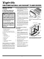
Assembling and Attaching
Brass Trim
1. Remove packaging from remaining
three pieces of brass trim.
2. Locate four brass screws, two adjust-
ing plates with set screws, and two
shims in the hardware packet.
3. Align shim under adjusting plate as
shown in Figure 6.
4. Slide one end of adjusting plate/shim
in slot on mitered edge of top brass trim
(see Figure 6).
5. Slide other end of adjusting plate/shim
in slot on mitered edge of side brass
trim (see Figure 6).
6. While firmly holding edges of brass
trim together, tighten both set screws
on the adjusting plate with slotted
screwdriver.
7. Repeat steps 1 through 6 for other side.
8. Place the assembled trim on front of
heater cabinet. Attach on top and sides
with four brass screws included in hard-
ware package (see Figure 7).
9. Reattach front panel to heater if you are
going to mount the heater to the base.
Do not reattach front panel at this time
if you are going to mount heater to wall.
Side Brass Trim
Top Brass Trim
Slot
Mitered Edge
Slot
Set Screws
Adjusting
Plate
Screws
Assembled
Brass Trim
Figure 7 - Attaching Brass Trim to Heater
Figure 6 - Assembling Brass Trim
Shim

6
103508
VENT-FREE NATURAL GAS RADIANT
®
FLAME HEATER
AIR FOR
COMBUSTION AND
VENTILATION
Today’s homes are built more energy effi-
cient than ever. New materials, increased
insulation, and new construction methods
help reduce heat loss in homes. Home owners
weather strip and caulk around windows and
doors to keep the cold air out and the warm air
in. During heating months, home owners
want their homes as airtight as possible.
While it is good to make your home energy
efficient, your home needs to breathe. Fresh
air must enter your home. All fuel-burning
appliances need fresh air for proper com-
bustion and ventilation.
Exhaust fans, fireplaces, clothes dryers, and
fuel burning appliances draw air from the
house to operate. You must provide ad-
equate fresh air for these appliances. This
will insure proper venting of vented fuel-
burning appliances.
PROVIDING ADEQUATE
VENTILATION
The following are excerpts from National
Fuel Gas Code. NFPA 54/ANS Z223.1, Sec-
tion 5.3, Air for Combustion and Ventila-
tion.
All spaces in homes fall into one of the three
following ventilation classifications:
1. Unusually Tight Construction
2. Unconfined Space
3. Confined Space
The information on pages 6 through 8 will
help you classify your space and provide
adequate ventilation.
Unusually Tight Construction
The air that leaks around doors and win-
dows may provide enough fresh air for
combustion and ventilation. However, in
buildings of unusually tight construction,
you must provide additional fresh air.
Unusually tight construction is de-
fined as construction where:
a. walls and ceilings exposed to the
outside atmosphere have a con-
tinuous water vapor retarder with
a rating of one perm (6x10
-11
kg
per pa-sec-m
2
) or less with open-
ings gasketed or sealed
and
b. weather stripping has been
added on openable windows and
doors
and
c. caulking or sealants are applied
to areas such as joints around
window and door frames, be-
tween sole plates and floors, be-
tween wall-ceiling joints, be-
tween wall panels, at penetra-
tions for plumbing, electrical, and
gas lines, and at other openings.
If your home meets all of the three
criteria above, you must provide ad-
ditional fresh air. See
Ventilation Air
From Outdoors
, page 8.
If your home does not meet all of the
three criteria above, proceed to
Deter-
mining Fresh-Air Flow for Heater
Location
, page 7.
Confined and Unconfined Space
The National Fuel Gas Code (ANS Z223.1,
1992 Section 5.3) defines a confined space
as a space whose volume is less than 50
cubic feet per 1,000 Btu per hour (4.8 m
3
per
kw) of the aggregate input rating of all
appliances installed in that space and an
unconfining space as a space whose volume
is not less than 50 cubic feet per 1,000 Btu
per hour (4.8 m
3
per kw) of the aggregate
input rating of all appliances installed in that
space. Rooms communicating directly with
the space in which the appliances are in-
stalled*, through openings not furnished
with doors, are considered a part of the
unconfined space.
This heater shall not be installed in a con-
fined space or unusually tight construction
unless provisions are provided for adequate
combustion and ventilation air.
* Adjoining rooms are communicating only
if there are doorless passageways or ventila-
tion grills between them.
WARNING: This heater shall
not be installed in a confined space
or unusually tight construction
unless provisions are provided
for adequate combustion and ven-
tilation air. Read the following in-
structions to insure proper fresh
air for this and other fuel-burning
appliances in your home.

7
103508
OWNER’S MANUAL
AIR FOR
COMBUSTION AND
VENTILATION
Continued
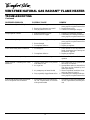
DETERMINING FRESH-AIR FLOW FOR HEATER LOCATION
Determining if You Have a Confined or Unconfined Space
Use this worksheet to determine if you have a confined or unconfined space.
Space: Includes the room in which you will install heater plus any adjoining rooms with doorless passageways or ventilation grills between
the rooms.
1. Determine the volume of the space (length x width x height).
Length x Width x Height = _____________________cu. ft. (volume of space)
Example:
Space size 20 ft. (length) x 16 ft. (width) x 8 ft. (ceiling height) = 2560 cu. ft. (volume of space)
If additional ventilation to adjoining room is supplied with grills or openings, add the volume of these rooms to the total volume of
the space.
2. Divide the space volume by 50 cubic feet to determine the maximum Btu/Hr the space can support.
_________________ (volume of space) ÷ 50 cu. ft. = (Maximum Btu/Hr the space can support)
Example: 2560 cu. ft. (volume of space) ÷ 50 cu. ft. =51.2 or 51,200 (maximum Btu/Hr the space can support)
3. Add the Btu/Hr of all fuel burning appliances in the space.
Vent-free heater _____________ Btu/Hr
Gas water heater* _____________ Btu/Hr
Gas furnace _____________ Btu/Hr
Vented gas heater _____________ Btu/Hr
Gas fireplace logs _____________ Btu/Hr
Other gas appliances* + _____________ Btu/Hr
Total = _____________ Btu/Hr
* Do not include direct-vent gas appliances. Direct-vent draws combustion air from the outdoors and vents to the outdoors.
4. Compare the maximum Btu/Hr the space can support with the actual amount of Btu/Hr used.
_____________ Btu/Hr (maximum the space can support)
_____________ Btu/Hr (actual amount of Btu/Hr used)
Example:
51,200 Btu/Hr (maximum the space can support)
58,000 Btu/Hr (actual amount of Btu/Hr used)
The space in the above example is a confined space because the actual Btu/Hr used is more than the maximum Btu/Hr the space can support.
You must provide additional fresh air. Your options are as follows:
A. Rework worksheet, adding the space of an adjoining room. If the extra space provides an unconfined space, remove door to adjoin-
ing room or add ventilation grills between rooms. See Ventilation Air From Inside Building, page 8.
B. Vent room directly to the outdoors. See Ventilation Air From Outdoors, page 8.
C. Install a lower Btu/Hr heater, if lower Btu/Hr size makes room unconfined.
If the actual Btu/Hr used is less than the maximum Btu/Hr the space can support, the space is an unconfined space. You will need no
additional fresh air ventilation.
Example:
Gas water heater 30,000 Btu/Hr
Vent-free heater + 28,000 Btu/Hr
Total = 58,000 Btu/Hr
WARNING: If the area in which the heater may be operated is smaller than that defined as an unconfined space
or if the building is of unusually tight construction, provide adequate combustion and ventilation air by one of
the methods described in the
National Fuel Gas Code, ANS Z223.1, 1992, Section 5.3,
or applicable local codes.
Continued

8
103508
VENT-FREE NATURAL GAS RADIANT
®
FLAME HEATER
Figure 9 - Ventilation Air from Outdoors
Outlet
Air
Ventilated
Attic
Outlet
Air
Inlet
Air
Inlet Air
Ventilated
Crawl Space
To
Crawl
Space
To Attic
Or
Remove
Door into
Adjoining
Room,
Option 3
Ventilation Grills
Into Adjoining Room,
Option 2
12"
12"
Ventilation
Grills
into Adjoining
Room,
Option 1
AIR FOR
COMBUSTION AND
VENTILATION
Continued
VENTILATION AIR
Ventilation Air From Inside
Building
This fresh air would come from an adjoining
unconfined space. When ventilating to an
adjoining unconfined space, you must pro-
vide two permanent openings: one within
12" of the ceiling and one within 12" of the
floor on the wall connecting the two spaces
(see options 1 and 2, Figure 8). You can also
remove door into adjoining room (see op-
tion 3, Figure 8). Follow the National Fuel
Gas Code NFPA 54/ANS Z223.1, Section
5.3, Air for Combustion and Ventilation for
required size of ventilation grills or ducts.
Figure 8 - Ventilation Air from Inside Building
WARNING: Rework work-
sheet, adding the space of the
adjoining unconfined space. The
combined spaces must have
enough fresh air to supply all
appliances in both spaces.
Ventilation Air From Outdoors
Provide extra fresh air by using ventilation
grills or ducts. You must provide two per-
manent openings: one within 12" of the
ceiling and one within 12" of the floor.
Connect these items directly to the outdoors
or spaces open to the outdoors.
IMPORTANT:
Do not provide openings for
inlet or outlet air into attic if attic has a
thermostat-controlled power vent. Heated air
entering the attic will activate the power vent.

9
103508
OWNER’S MANUAL
INSTALLATION
NOTICE: A qualified service per-
son must install heater. Follow
all local codes.
CHECK GAS TYPE
Use only natural gas. If your gas supply is
not natural gas, do not install heater. Call
dealer where you bought heater for proper
type heater.
INSTALLATION ITEMS
Before installing heater, make sure you have
the items listed below.
• piping (check local codes)
• sealant (resistant to propane/LP gas)
• manual shutoff valve *
• ground joint union
• test gauge connection *
• sediment trap
• tee joint
• pipe wrench
* An A.G.A. design-certified manual shutoff
valve with 1/8" NPT tap is an acceptable
alternative to test gauge connection. Pur-
chase the optional A.G.A. design-certified
manual shutoff valve from your dealer. See
Accessories, pages 24 and 25.
LOCATING HEATER
WARNING: Maintain the mini-
mum clearances shown in Figure
10. If you can, provide greater
clearances from floor, ceiling, and
joining wall.
You can locate heater on floor. The optional
hearth base is needed. You can also install
the optional decorative mantel on the heater
(some mantels require hearth base).
IMPORTANT
: Only use optional mantel
and hearth base specified in this manual.
Purchase the optional mantel and hearth
base from your dealer. See Accessories,
pages 24 and 25.
The heater may also be mounted on a wall.
You cannot use optional mantel if mounting
heater on a wall.
WARNING: Never install the
heater
• in a bedroom or bathroom
• in a recreational vehicle
• where curtains, furniture,
clothing, or other flammable
objects are less than 36 inches
from the front, top, or sides of
the heater
• as a fireplace insert
• in high traffic areas
• in windy or drafty areas
CAUTION: This heater cre-
ates warm air currents. These
currents move heat to wall sur-
faces next to heater. Installing
heater next to vinyl or cloth wall
coverings or operating heater
where impurities (such as to-
bacco smoke, aromatic candles,
cleaning fluids, oil or kerosene
lamps, etc.) in the air exist, may
discolor walls.
IMPORTANT:
Vent-free heaters add mois-
ture to the air. Although this is beneficial,
installing heater in rooms without enough
ventilation air may cause mildew to form
from too much moisture. See Air for Com-
bustion and Ventilation, pages 6 through 8.
NOTICE: This heater is intended
for use as supplemental heat. Use
this heater along with your pri-
mary heating system. Do not in-
stall this heater as your primary
heat source. If you have a central
heating system, you may run
system’s circulating blower while
using heater. This will help circu-
late the heat throughout the
house. In the event of a power
outage, you can use this heater
as your primary heat source.
CAUTION: If you install the
heater in a home garage
• heater pilot and burner must
be at least 18 inches above
floor.
• locate heater where moving ve-
hicle will not hit it.
For convenience and efficiency, install heater
• where there is easy access for operation,
inspection, and service.
• in coldest part of room.
An optional fan kit is available from your
dealer. See Accessories, pages 24 and 25. If
planning to use fan, locate heater near an
electrical outlet.
Figure 10 - Mounting Clearances As
Viewed From Front of Heater
36"
5"
FLOOR
CEILING
Minimum
Minimum To
Of Carpeting
Combustibl
e
6"
Minimum
From
Sides Of
Heater
Left
Side
Right
Side
Continued
Minimum to Top
Surface of Carpeting,
Tile or Other
Combustible Material

10
103508
VENT-FREE NATURAL GAS RADIANT
®
FLAME HEATER
Attaching Mounting Bracket To
Wall
Note:
Wall anchors, mounting screws, and
spacers are in hardware package. The hard-
ware package is provided with heater.
Attaching To Wall Stud Method
For attaching mounting bracket to wall studs
1. Drill holes at marked locations using
9/64" drill bit.
2. Place mounting bracket onto wall. Line
up last hole on each end of bracket with
holes drilled in wall.
3. Insert mounting screws through bracket
and into wall studs.
4. Tighten screws until mounting bracket
is firmly fastened to wall studs.
INSTALLATION OPTIONS
There are three options for mounting this
heater.
A.Mounting heater to wall
B. Mounting heater to optional hearth base
C. Mounting heater with optional hearth
base to optional mantel
A. MOUNTING HEATER TO
WALL
Mounting Bracket
The mounting bracket is located on back
panel of heater. It has been taped there for
shipping. Remove mounting bracket from
back panel.
20 3/4"
Min.
11"
Min.
16"
Adjoining Wall
Only Insert Mounting
Screws Through Last
Hole On Each End
Floor
Figure 13 - Mounting Bracket Clearances
Mounting
Bracket
Figure 12 - Mounting Bracket Location
Methods For Attaching
Mounting Bracket To Wall
Only use last hole on each end of mounting
bracket to attach bracket to wall. These two
holes are 16 inches apart from their centers.
Attach mounting bracket to wall in one of
two ways.
1. Attaching to wall stud
2. Attaching to wall anchor
Attaching To Wall Stud This method
provides the strongest hold. Insert mounting
screws through mounting bracket and into
wall studs.
Attaching To Wall Anchor This method
allows you to attach mounting bracket to
hollow walls (wall areas between studs) or
to solid walls (concrete or masonry).
Decide which method better suits your needs.
Either method will provide a secure hold for
the mounting bracket.
Marking Screw Locations
1. Tape mounting bracket to wall where
heater will be located. Make sure
mounting bracket is level.
WARNING: Maintain minimum
clearances shown in Figure 13. If
you can, provide greater clear-
ances from floor and joining wall.
2. Mark screw locations on wall (see Fig-
ure 13).
Note:
Only mark last hole on each end
of mounting bracket. Insert mounting
screws through these holes only.
3. Remove tape and mounting bracket
from wall.
INSTALLATION
Continued
THERMOSTAT SENSING
BULB
The thermostat sensing bulb has been placed
inside the heater for protection during ship-
ping.
Locating Thermostat Sensing
Bulb
1. Remove front panel of heater (see Fig-
ure 2, page 4).
2. Locate thermostat sensing bulb just
under burner assembly.
IMPORTANT
: Attach thermostat sensing
bulb to back of heater for proper operation.
Attaching Thermostat Sensing
Bulb
1. Remove thermostat sensing bulb from
holders inside heater. Route through
slot opening in bottom of heater.
2. Place clamp on thermostat sensing bulb
as shown in Figure 11. Clamp is pro-
vided in hardware package.
3. Snap clamp into upper mounting hole
as shown in Figure 11. Mounting hole
is located on lower left edge on back
of heater. Make sure the thermostat
sensing bulb is pointing up.
Figure 11 - Attaching Thermostat Sensing
Bulb
Thermostat
Sensing Bulb
Clamp

11
103508
OWNER’S MANUAL
INSTALLATION
Continued
Attaching To Wall Anchor Method
For attaching mounting bracket to hollow
walls (wall areas between studs) or solid
walls (concrete or masonry)
1. Drill holes at marked locations using
5/16" drill bit. For solid walls (concrete
or masonry), drill at least 1" deep.
2. Fold wall anchor as shown in Figure 14.
3. Insert wall anchor (wings first) into
hole. Tap anchor flush to wall.
4. For thin walls (1/2" or less), insert
red key into wall anchor. Push red
key to “pop” open anchor wings.
IMPORTANT:
Do not hammer key!
For thick walls (over 1/2" thick) or solid
walls, do not pop open wings.
5. Place mounting bracket onto wall. Line
up last hole on each end of bracket with
wall anchors.
6. Insert mounting screws through bracket
and into wall anchors.
7. Tighten screws until mounting bracket
is firmly fastened to wall.
Figure 14 - Folding Anchor
Continued
Figure 15 - Popping Open Anchor Wings
For Thin Walls
Horizontal Slots
Mounting Bracket
(attached to wall)
Stand-Out
Tab
Figure 16 - Mounting Heater Onto
Mounting Bracket
Placing Heater On Mounting
Bracket
1. Locate two horizontal slots on back
panel of heater.
2. Place heater onto mounting bracket.
Slide horizontal slots onto stand-out
tabs on mounting bracket.
Installing Bottom Mounting
Screws
1. Locate two bottom mounting holes.
These holes are near bottom on back
panel of heater (see Figure 17).
2. Mark screw locations on wall.
3. Remove heater from mounting bracket.
4. If installing bottom mounting screws
into hollow or solid wall, install wall
anchors. Follow steps 1 through 4 un-
der Attaching To Wall Anchor Method.
If installing bottom mounting screw
into wall stud, drill holes at marked lo-
cations using 9/64" drill bit.
5. Replace heater onto mounting bracket.
6. Place spacers between bottom mount-
ing holes and wall anchor or drilled hole.
7. Hold spacer in place with one hand.
With other hand, insert mounting screw
through bottom mounting hole and
spacer. Place tip of screw in opening
of wall anchor or drilled hole.
Figure 17 - Installing Bottom Mounting
Screws
8. Tighten both screws until heater is
firmly secured to wall. Do not over
tighten.
Note:
Do not replace front panel at this
time. Replace front panel after making
gas connections and checking for leaks
(see pages 13 and 14).

12
103508
VENT-FREE NATURAL GAS RADIANT
®
FLAME HEATER
Mounting Heater to Optional
Hearth Base
1. Lay heater on its back on a table with
the bottom of heater overhanging the
edge of the table.
2. Remove 2 shipping screws in bottom
of heater. Discard shipping screws.
3. Line up mounting holes on top of hearth
base with holes in bottom of heater (see
Figure 18).
4. Using a Phillips screwdriver, secure
hearth base to heater with four sheet
metal screws (see Figure 18).
5. Stand heater up on base.
6. Place hearth insert in hearth base as
shown in Figure 19.
7. Assemble brass trim (see steps 1
through 7 under Assembling and At-
taching Brass Trim, page 5).
8. Slide base trim on heater base. Attach
brass trim to base with two brass screws
included as shown in Figure 19.
Figure 19 - Placing Hearth Insert on Heater
Base and Attaching Brass Base Trim
Brass Base Trim
Figure 18 - Attaching Heater to Hearth
Base
Hearth
Insert
Laminate Sheet
Screw
WARNING: If installing the
GHB802 or GHB802A base on
heater, and using with a GA se-
ries heater blower accessory
along with a GS601 surround or a
GM800 or GM900 series mantel,
the surround or mantel clearance
to back wall should be 3/4 inch.
This will improve flame appear-
ance and combustion.
Use only a GHB802B, GHB802C,
or GHB38 series hearth base if
using a GA series heater blower
accessory with a GM700 series,
GMC32F series, or GMC33U se-
ries mantel.
INSTALLATION
Continued
Tools needed:
• #2 Phillips screwdriver
• slotted screwdriver
• electric drill (if securing base to floor)
The optional hearth base kit includes the
following:
• Hearth Base
• 4 Wood Screws
• 4 Sheet Metal Screws
• Brass Base Trim
• Hearth Insert
• 4 Anchors
• Laminate Sheet & Adhesive
• 2 Brass Screws
Note:
It is an option to secure GHB802A
model hearth base to floor. You must secure
the GHB802B, GHB802C, or GHB38 se-
ries model hearth base to floor. To secure
hearth base to floor, follow instructions un-
der Securing Hearth Base to Floor. If not
securing hearth base to floor, proceed to
Mounting Heater to Optional Hearth Base.
B. MOUNTING HEATER ON
OPTIONAL HEARTH BASE
Securing Hearth Base to Floor
1. Position hearth base in desired location.
Mark holes for drilling (See Figure 18).
Remove hearth base.
2. For carpeted floor, make a small cut with
a sharp knife at marked locations before
drilling. If securing to a wood floor, drill
a 3/4" deep hole using a 1/8" diameter
drill bit. Do not use anchors in wood
floors.
If securing to a concrete floor, drill a
1
3
/8" deep hole using a 1/4" diameter
concrete drill bit. Completely insert
anchors into each hole.
3. Mount heater to hearth base following
steps under Mounting Heater to Op-
tional Hearth Base. After mounting
heater, position heater and hearth base
over drilled holes. With slotted screw-
driver, secure hearth base to floor with
four wood screws.
Base
Holes for
Securing
Heater to Floor
Shipping
Screw
Bottom of Heater
Sheet Metal
Screw
Mounting
Holes

13
103508
OWNER’S MANUAL
CONNECTING TO GAS
SUPPLY
NOTICE: A qualified service per-
son must connect heater to gas
supply. Follow all local codes.
IMPORTANT:
Check gas line pressure be-
fore connecting heater to gas line. Gas line
pressure must be no greater than 14 inches
of water. If gas line pressure is higher,
heater regulator damage could occur.
Installation must include a manual shutoff
valve, union, and plugged 1/8" NPT tap.
Locate NPT tap within reach for test gauge
hook up. NPT tap must be upstream from
heater (see Figure 20).
Apply pipe joint sealant lightly to male
threads. This will prevent excess sealant
from going into pipe. Excess sealant in pipe
could result in clogged heater valves.
WARNING: Never connect
heater to private (non-utility) gas
wells. This gas is commonly
known as wellhead gas.
CAUTION : Use only new,
black iron or steel pipe. Inter-
nally-tinned copper tubing may
be used in certain areas. Check
your local codes. Use pipe of 1/2"
or greater diameter to allow
proper gas volume to heater. If
pipe is too small, undue loss of
pressure will occur.
CAUTION: Use pipe joint seal-
ant that is resistant to liquid pe-
troleum (LP) gas.
INSTALLATION
Continued
C. MOUNTING HEATER
WITH
OPTIONAL HEARTH BASE
TO OPTIONAL MANTEL See
instructions included with
mantel kit.
Assembling Mantel
IMPORTANT:
Only use the optional man-
tels specified in this manual. See Accesso-
ries, pages 24 and 25 for proper mantel kits.
This heater is only approved for use with
models GMF800(A,B)/GMU801(A,B),
GM900F(A,B)/GM901U(A,B), GM700F/
GM701U, GMC22F/GMC23U/GMC24U,
GMC32F(B)/GMC33U(B), and GMC26F/
GMC27U/GMC28F mantel kits. Using any
other mantel will void the A.G.A. approval
for this heater. Do not use models
GMF800(A,B)/GMU801(A,B),
GM900F(A,B)/GM901U(A,B), and
GM700F/GM701U, GMC22F/GMC23U/
GMC24U, GMC32F(B)/GMC33U(B), and
GMC26F/GMC27U/GMC28F mantels with
any other product. Before installing mantel
to heater, the heater must be mounted on the
optional hearth base.
Installing Mantel to Heater
WARNING: If installing the
GHB802 or GHB802A base on
heater, and using with a GA se-
ries heater blower accessory
along with a GS601 surround or a
GM800 or GM900 series mantel,
the surround or mantel clearance
to back wall should be 3/4 inch.
This will improve flame appear-
ance and combustion.
Use only a GHB802B, GHB802C,
OR GHB38 series hearth base if
using a GA series heater blower
accessory with a GM700 series,
GMC32F series, or GMC33U se-
ries mantel.
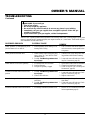
Install sediment trap in supply line as shown
in Figure 20. Locate sediment trap where it
is within reach for cleaning. Locate sedi-
ment trap where trapped matter is not likely
to freeze. A sediment trap traps moisture
and contaminants. This keeps them from
going into heater controls. If sediment trap
is not installed or is installed wrong, heater
may not run properly.
CAUTION: Avoid damage to
control. Hold gas fitting with
wrench when connecting it to gas
piping and/or fittings.
Figure 20 - Gas Connection
* An A.G.A. design-certified manual shutoff valve with 1/8" NPT tap is an acceptable
alternative to test gauge connection. Purchase the optional A.G.A. design-certified manual
shutoff valve from your dealer. See Accessories, pages 24 and 25.
Tee Joint
Reducer
Bushing to
1/8" NPT
1/8" NPT
Plug Tap
Test
Gauge
Connection *
Tee Joint
Pipe
Nipple
Cap
Sediment
Trap
Pressure
Regulator
3/8" NPT
Pipe Nipple
Ground Union
Joint
Heater
Cabinet
3" Minimum
Note:
Burner
bracket not
shown for clarity
Manual Shutoff Valve *
From Gas Meter
(4" W.C. to 10.5" W.C.
Pressure)
Continued

14
103508
VENT-FREE NATURAL GAS RADIANT
®
FLAME HEATER
ON
POSITION
OFF
POSITION
Open
Closed
Manual
Shutoff Valve
Manual
Shutoff
Valve
Thermostat Gas Valve Location
Figure 21 - Manual Shutoff Valve
Gas Meter
Figure 22 - Checking Gas Joints
Pressure Testing Gas Supply
Piping System
Test Pressures In Excess Of 1/2 PSIG
1. Disconnect heater and its individual
manual shutoff valve from gas supply
piping system. Pressures in excess of
1/2 psig will damage heater regulator.
2. Cap off open end of gas pipe where
manual shutoff valve was connected.
3. Pressurize supply piping system by ei-
ther using compressed air or
opening main gas valve located on or
near gas meter.
4. Check all joints of gas supply piping
system. Apply mixture of liquid soap
and water to gas joints. Bubbles form-
ing show a leak.
5. Correct all leaks at once.
6. Reconnect heater and manual shutoff
valve to gas supply. Check reconnected
fittings for leaks.
CHECKING GAS
CONNECTIONS
WARNING: Test all gas pip-
ing and connections for leaks
after installing or servicing. Cor-
rect all leaks at once.
WARNING: Never use an open
flame to check for a leak. Apply a
mixture of liquid soap and water
to all joints. Bubbles forming
show a leak. Correct all leaks at
once.
INSTALLATION
Continued
Test Pressures Equal To or Less Than
1/2 PSIG
1. Close manual shutoff valve (see Fig-
ure 21).
2. Pressurize supply piping system by ei-
ther using compressed air or opening
main gas valve located on or near gas
meter.
3. Check all joints from gas meter to
manual shutoff valve (see Figure 22).
Apply mixture of liquid soap and wa-
ter to gas joints. Bubbles forming show
a leak.
4. Correct all leaks at once.
Pressure Testing Heater Gas
Connections
1. Open manual shutoff valve (see Fig-
ure 21).
2. Open main gas valve located on or near
gas meter.
3. Make sure control knob of heater is in
the OFF position.
4. Check all joints from manual shutoff
valve to thermostat gas valve (see Fig-
ure 22). Apply mixture of liquid soap
and water to gas joints. Bubbles form-
ing show a leak.
5. Correct all leaks at once.
6. Light heater (see Operating Heater,
pages 15 and 16). Check all other in-
ternal joints for leaks.
7. Turn off heater (see To Turn Off Gas to
Appliance, page 15).
8. Replace front panel.

15
103508
OWNER’S MANUAL
OPERATING
HEATER
FOR YOUR SAFETY
READ BEFORE
LIGHTING
A. This appliance has a pilot which must
be lighted by hand. When lighting the
pilot, follow these instructions exactly.
B. BEFORE LIGHTING smell all
around the appliance area for gas. Be
sure to smell next to the floor because
some gas is heavier than air and will
settle on the floor.
WHAT TO DO IF YOU SMELL
GAS
• Do not try to light any appliance.
• Do not touch any electric switch; do
not use any phone in your building.
• Immediately call your gas supplier
from a neighbor’s phone. Follow
the gas supplier’s instructions.
• If you cannot reach your gas sup-
plier, call the fire department.
C. Use only your hand to push in or turn
the gas control knob. Never use tools.
If the knob will not push in or turn
by hand, don’t try to repair it, call a
qualified service technician or gas
supplier. Force or attempted repair
may result in a fire or explosion.
D. Do not use this appliance if any part
has been under water. Immediately
call a qualified service technician to
inspect the appliance and to replace
any part of the control system and
any gas control which has been un-
der water.
WARNING: If you do not fol-
low these instructions exactly, a
fire or explosion may result caus-
ing property damage, personal
injury or loss of life.
Continued
LIGHTING
INSTRUCTIONS
1. STOP! Read the safety information
above.
2. Make sure manual shutoff valve is
fully open.
3. Turn control knob clockwise
Clockwise
to the OFF position.
4. Wait five (5) minutes to clear out any
gas. Then smell for gas, including
near the floor. If you smell gas,
STOP! Follow “B” in the safety in-
formation. If you don’t smell gas, go
to the next step.
5. Turn control knob counterclockwise
C-clockwise
to the PILOT position. Press
in control knob for five (5) seconds
(see Figure 23).
Note:
You may be running this
heater for the first time after hook-
ing up to gas supply. If so, the con-
trol knob may need to be pressed in
for 30 seconds. This will allow air to
bleed from the gas system.
6. With control knob pressed in, push
down and release ignitor button. This
will light pilot. The pilot is attached
to the front of burner. If needed, keep
pressing ignitor button until pilot
lights.
Note:
If pilot does not stay lit, refer
to Troubleshooting , pages 17 through
19. Also contact a qualified service
person or gas supplier for repairs.
Until repairs are made, light pilot with
match. To light pilot with match, see
Manual Lighting Procedure , page 16.
Figure 23 - Control Knob In The OFF
Position
7. Keep control knob pressed in for 30
seconds after lighting pilot. After 30
seconds, release control knob.
• If control knob does not pop up
when released, contact a qualified
service person or gas supplier for
repairs.
Note:
If pilot goes out, repeat steps
3 through 7. This heater has a safety
interlock system. Wait one (1) minute
before lighting pilot again.
8. Turn control knob counterclockwise
C-clockwise
to desired heating level. The
main burner should light. Set control
knob to any heat level between HI
and LO.
GRH/OV 015Control Knob & I
g
nitor Button
PILOT
LO
OFF
HI
IGNITOR
Ignitor
Button
Control
Knob
Thermocouple
Pilot Burner
Figure 24 - Pilot
Ignitor Electrode
CAUTION: Do not try to adjust
heating levels by using the
manual shutoff valve.
TO TURN OFF GAS
TO APPLIANCE
Shutting Off Heater
1. Turn control knob clockwise
Clockwise
to the OFF position.
2. Turn off all electric power to the ap-
pliance if service is to be performed.
Shutting Off Burner Only (pilot
stays lit)
1. Turn control knob clockwise
Clockwise
to the PILOT position.

16
103508
VENT-FREE NATURAL GAS RADIANT
®
FLAME HEATER
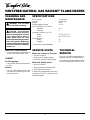
BURNER FLAME PATTERN
Figure 27 shows a correct burner flame
pattern. Figure 28 shows an incorrect burner
flame pattern. The incorrect burner flame
pattern shows yellow tipping of the flame. It
also shows the flame higher than one inch
above the log.
Note:
When using the heater the first time,
the flame will be yellow for approximately
one hour until the log cures.
NOTICE: Do not mistake orange
flames with yellow tipping. Dirt
or other fine particles enter the
heater and burn causing brief
patches of orange flame.
If burner flame pattern is incorrect, as shown
in Figure 28
• turn heater off (see To Turn Off Gas to
Appliance, page 15)
• see Troubleshooting, pages 17 through 19
CORRECT FLAME PATTERN
AT HIGH POSITION
Yellow Tipping
Figure 28 - Incorrect Burner Flame Pattern
Top of Flame About One
Inch Above Logs
WARNING: If yellow tipping
occurs, your heater could pro-
duce increased levels of carbon
monoxide. If burner flame pat-
tern shows yellow tipping, follow
instructions at bottom of this
page.
INSPECTING
BURNER
Check pilot flame pattern and burner flame
pattern often.
PILOT FLAME PATTERN
Figure 25 shows a correct pilot flame pat-
tern. Figure 26 shows an incorrect pilot
flame pattern. The incorrect pilot flame is
not touching the thermocouple. This will
cause the thermocouple to cool. When the
thermocouple cools, the heater will shut
down.
If pilot flame pattern is incorrect, as shown
in Figure 26
• turn heater off (see To Turn Off Gas to
Appliance, page 15)
• see Troubleshooting, pages 17 through 19
Figure 25 - Correct Pilot Flame Pattern
Bad Pilot-Nat. Port GRH/OV 007E
Pilot Burner
Thermocouple
Figure 26 - Incorrect Pilot Flame Pattern
OPERATING
HEATER
Continued
The thermostatic control used on this
heater differs from standard thermostats.
Standard thermostats simply turn on and
off the burner. The thermostat used on
this heater senses the room temperature.
The thermostat adjusts the amount of gas
flow to the burner. This increases or de-
creases the burner flame height. At times
the room may exceed the set tempera-
ture. If so, the burner will shut off. The
burner will cycle back on when room
temperature drops below the set tem-
perature. The control knob can be set to
any heat level between HI and LO.
Note
: The thermostat sensing bulb mea-
sures the temperature of air near the
heater cabinet. This may not always agree
with room temperature (depending on
housing construction, installation loca-
tion, room size, open air temperatures,
etc.). Frequent use of your heater will let
you determine your own comfort levels.
1. Remove front panel (see Figure 2,
page 4).
2. Follow steps 1 through 5 under Light-
ing Instructions, page 15.
3. With control knob pressed in, strike
match. Hold match to pilot until pi-
lot lights.
4. Keep control knob pressed in for 30
seconds after lighting pilot. After 30
seconds, release control knob.
5. Replace front panel.
6. Turn control knob counterclockwise
C-clockwise
to desired heating level. The
main burner should light. Set control
knob to any heat level between HI
and LO.
THERMOSTAT
CONTROL OPERATION
MANUAL LIGHTING
PROCEDURE
Thermocouple
Pilot Burner
Figure 27 - Correct Burner Flame Pattern

17
103508
OWNER’S MANUAL
Note:
All troubleshooting items are listed in
order of operation.
TROUBLESHOOTING
OBSERVED PROBLEM
When ignitor button is pressed, there is no
spark at ODS/pilot
When ignitor button is pressed, there is
spark at ODS/pilot but no ignition
ODS/pilot lights but flame goes out when
control knob is released
CAUTION: Never use a wire,
needle, or similar object to clean
ODS/pilot. This can damage ODS/
pilot unit.
WARNING: Turn off and un-
plug heater and let cool before
servicing. Only a qualified ser-
vice person should service and
repair heater.
POSSIBLE CAUSE
1. Ignitor cable pinched or wet
2. Ignitor electrode not connected to igni-
tor cable
3. Piezo ignitor nut is loose
4. Broken ignitor cable
5. Ignitor electrode broken
6. Bad piezo ignitor
7. Ignitor electrode positioned wrong
1. Gas supply turned off or manual shutoff
valve closed
2. Control knob not in PILOT position
3. Control knob not pressed in while in
PILOT position
4. Air in gas lines when installed
5. ODS/pilot is clogged
6. Gas regulator setting is not correct
1. Control knob not fully pressed in
2. Control knob not pressed in long enough
3. Safety interlock system has been
triggered
4. Manual shutoff valve not fully open
5. Thermocouple connection loose at con-
trol valve
6. Pilot flame not touching thermocouple,
which allows thermocouple to cool,
causing pilot flame to go out. This prob-
lem could be caused by one or both of
the following:
A) Low gas pressure
B) Dirty or partially clogged ODS/pilot
7. Thermocouple damaged
8. Control valve damaged
REMEDY
1. Free ignitor cable if pinched by any
metal or tubing. Keep ignitor cable dry
2. Reconnect ignitor cable
3. Tighten nut holding piezo ignitor to base
panel of log set. Nut is located behind
base panel
4. Replace ignitor cable
5. Replace ignitor
6. Replace piezo ignitor
7. Replace ignitor
1. Turn on gas supply or open manual
shutoff valve
2. Turn control knob to PILOT position
3. Press in control knob while in PILOT
position
4. Continue holding down control knob.
Repeat igniting operation until air is
removed
5. Clean ODS/pilot (see Cleaning and
Maintenance, page 20) or replace ODS/
pilot assembly
6. Replace gas regulator
1. Press in control knob fully
2. After ODS/pilot lights, keep control
knob pressed in 30 seconds
3. Wait one minute for safety interlock sys-
tem to reset. Repeat ignition operation
4. Fully open manual shut-off valve
5. Hand tighten until snug, then tighten
1/4 turn more
6. A) Contact local natural gas company
B) Clean ODS/pilot (see Cleaning and
Maintenance, page 20) or replace ODS/
pilot assembly
7. Replace thermocouple
8. Replace control valve
Continued

18
103508
VENT-FREE NATURAL GAS RADIANT
®
FLAME HEATER
OBSERVED PROBLEM
Burner does not light after ODS/pilot is lit
Delayed ignition of burner
Burner backfiring during combustion
Yellow flame during burner combustion
Slight smoke or odor during initial operation
Heater produces a whistling noise when
burner is lit
White powder residue forming within burner
box or on adjacent walls or furniture
REMEDY
1. Clean burner (see Cleaning and Mainte-
nance, page 20) or replace burner orifice
2. Replace burner orifice
3. Contact local natural gas company
1. Contact local natural gas company
2. Clean burner (see Cleaning and Mainte-
nance, page 20) or replace burner orifice
1. Clean burner (see Cleaning and Mainte-
nance, page 20) or replace burner orifice
2. Replace burner
3. Replace gas regulator
1. Check burner for dirt and debris. If
found, clean burner (see Cleaning and
Maintenance, page 20)
2. Replace gas regulator
1. Problem will stop after a few hours of
operation
1. Turn control knob to LO position and
let warm up for a minute
2. Operate burner until air is removed from
line. Have gas line checked by local
natural gas company
3. Observe minimum installation clear-
ances (see Figure 10, page 9)
4. Clean burner (see Cleaning and Mainte-
nance, page 20) or replace burner orifice
1. Turn heater off when using furniture pol-
ish, wax, carpet cleaners, or similar prod-
ucts
POSSIBLE CAUSE
1. Burner orifice is clogged
2. Burner orifice diameter is too small
3. Inlet gas pressure is too low
1. Manifold pressure is too low
2. Burner orifice is clogged
1. Burner orifice is clogged or damaged
2. Burner damaged
3. Gas regulator defective
1. Not enough air
2. Gas regulator defective
1. Residues from manufacturing processes
1. Turning control knob to HI position
when burner is cold
2. Air in gas line
3. Air passageways on heater blocked
4. Dirty or partially clogged burner orifice
1. When heated vapors from furniture pol-
ish, wax, carpet cleaners, etc. turn into
white powder residue
TROUBLESHOOTING
Continued

19
103508
OWNER’S MANUAL
TROUBLESHOOTING
Continued
OBSERVED PROBLEM
Heater produces a clicking/ticking noise
just after burner is lit or shut off
Heater produces unwanted odors
Heater shuts off in use (ODS operates)
Gas odor even when control knob is in OFF
position
Gas odor during combustion
Moisture/condensation noticed on windows
REMEDY
1. This is common with most heaters. If
noise is excessive, contact qualified ser-
vice person
1. Ventilate room. Stop using odor caus-
ing products while heater is running
2. Locate and correct all leaks (see Check-
ing Gas Connections, page 14)
1. Open window and/or door for ventilation
2. Contact local natural gas company
3. Clean ODS/pilot (see Cleaning and
Maintenance, page 20)
1. Locate and correct all leaks (see Check-
ing Gas Connections, page 14)
2. Replace control valve
1. Take apart gas tubing and remove for-
eign matter
2. Locate and correct all leaks (see Check-
ing Gas Connections, page 14)
1. Refer to Air for Combustion and Venti-
lation requirements (page 6)
POSSIBLE CAUSE
1. Metal expanding while heating or con-
tracting while cooling
1. Heater burning vapors from paint, hair
spray, glues, etc. (see
IMPORTANT
statement above)
2. Gas leak. See Warning statement at
top of page
1. Not enough fresh air is available
2. Low line pressure
3. ODS/pilot is partially clogged
1. Gas leak. See Warning statement at
top of page
2. Control valve defective
1. Foreign matter between control valve
and burner
2. Gas leak. See Warning statement at
top of page
1. Not enough combustion/ventilation air.
WARNING: If you smell gas
• Shut off gas supply.
• Do not try to light any appliance.
• Do not touch any electrical switch; do not use any phone in your building.
• Immediately call your gas supplier from a neighbor’s phone. Follow the gas
supplier’s instructions.
• If you cannot reach your gas supplier, call the fire department.
IMPORTANT:
Operating heater where impurities in air exist may create odors. Cleaning supplies, paint, paint
remover, cigarette smoke, cements and glues, new carpet or textiles, etc., create fumes. These fumes may mix
with combustion air and create odors.

20
103508
VENT-FREE NATURAL GAS RADIANT
®
FLAME HEATER
CLEANING AND
MAINTENANCE
ODS/PILOT AND BURNER
• Use a vacuum cleaner, pressurized air,
or small, soft bristled brush to clean.
CABINET
Air Passageways
• Use a vacuum cleaner or pressurized air
to clean.
Exterior
• Use a soft cloth dampened with a mild
soap and water mixture. Wipe the cabi-
net to remove dust.
TECHNICAL
SERVICE
You may have further questions about in-
stallation, operation, or troubleshooting.
If so, contact DESA International’s Techni-
cal Service Department at 1-800-323-5190.
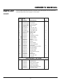
BTU (Variable) 14,000/28,000
Type Gas Natural Only
Ignition Piezo
Pressure Regulator Setting 3" W.C.
Inlet Gas Pressure (in. of water) *
Maximum 10.5"
Minimum 5"
Dimensions, Inches (H x W x D)
Heater 23.75 x 25.9 x 8.5
Carton 26 x 27.75 x 10.25
Weight (pounds)
Heater 29
Shipping 35
* For purposes of input adjustment
SPECIFICATIONS
When Gas Pressure Is Too Low
• pilot will not stay lit
• burner will have delayed ignition
• heater will not produce specified heat
When Gas Quality Is Bad
• pilot will not stay lit
• burner will produce flames and soot
• heater will backfire when lit
You may feel your gas pressure is too low or
gas quality is bad. If so, contact your local
natural gas supplier.
SERVICE HINTS
CAUTION : You must keep
control areas, burner, and circu-
lating air passageways of heater
clean. Inspect these areas of
heater before each use. Have
heater inspected yearly by a quali-
fied service person. Heater may
need more frequent cleaning due
to excessive lint from carpeting,
pet hair, etc.
WARNING: Turn off heater
and let cool before cleaning.
Page is loading ...
Page is loading ...
Page is loading ...
Page is loading ...
Page is loading ...
Page is loading ...
-
 1
1
-
 2
2
-
 3
3
-
 4
4
-
 5
5
-
 6
6
-
 7
7
-
 8
8
-
 9
9
-
 10
10
-
 11
11
-
 12
12
-
 13
13
-
 14
14
-
 15
15
-
 16
16
-
 17
17
-
 18
18
-
 19
19
-
 20
20
-
 21
21
-
 22
22
-
 23
23
-
 24
24
-
 25
25
-
 26
26


Comfort Glow RFN28TC Owner's manual
- Category
- Space heaters
- Type
- Owner's manual
Ask a question and I''ll find the answer in the document
Finding information in a document is now easier with AI
Related papers
Other documents
-
World Marketing of America 602-30 User manual
-
 LC Prime MG050 Installation guide
-
Desa Tech VMH2800TNC Owner's manual
-
 ProCom Heating PF09B User manual
-
-
-
Desa Tech GM280TLP Owner's manual
-
Desa Tech A User manual
-
 Architectural Mailboxes 3582SN-A Installation guide
-
Architectural Mailboxes 3582PB-0 Installation guide


