The Series V6 FLOTECT
®
Flow Switch is an inexpensive, explosion-proof flow
switch for use on air, water or other compatible gases and liquids. Three configu-
rations are available - 1. Factory installed in a tee. 2. With a trimmable vane for
field adjustment and installation in a suitable tee. 3. Low flow models with an inte-
gral tee and adjustable valve. All are available with an optional enclosure which is
UL and CSA listed, or Directive 2014/34/EU (ATEX) compliant for
II 2 G Ex db IIC T6 Gb
Process Temp≤75°C or IECEx compliant for Ex db IIC T6 Gb Process Temp ≤
75°C.
Series V6 FLOTECT
®
Flow Switch
Specifications - Installation and Operating Instructions
Bulletin E-22
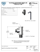
ELECTRICAL CONNECTIONS
Connect wire leads in accordance with local electrical codes and switch action
required. N.O. contacts will close and N.C. contacts will open when flow increases
to the actuation point. They will return to “normal” condition when flow decreases
to the deactuation point. Black = Common, Blue = Normally Open and Red =
Normally Closed.
For units supplied with both internal ground and external bonding terminals, the
ground screw inside the housing must be used to ground the control. The external
bonding screw is for supplementary bonding when allowed or required by local
code. When external bonding conductor is required, conductor must be wrapped a
minimum of 180° about the external bonding screw. See below. Some CSA listed
models are furnished with a separate green ground wire. Such units must be
equipped with a junction box, not supplied but available on special order.
W.E. ANDERSON DIV., DWYER INSTRUMENTS, INC.
P.O. BOX 358 • MICHIGAN CITY, INDIANA 46360 U. S. A.
Phone: 219/879-8000 www.dwyer-inst.com
Fax: 219/872-9057 e-mail: info@dwyermail.com
S
PECIFICATIONS
Service: Gases or liquids compatible with wetted materials.
W
etted Materials: Standard V6 Models: Vane: 301 SS; Lower Body: brass or 303
S
S; Magnet: ceramic; Other: 301, 302 SS; Tee: brass, iron, forged steel, or 304 SS.
V6 Low Flow Models: Lower Body: brass or 303 SS; Tee: brass or 304 SS; Magnet:
c
eramic; O-ring: Buna-N standard, Fluoroelastomer optional; Other: 301, 302 SS.
Temperature Limits: -4 to 220°F (-20 to 105°C) Standard, MT high temperature
o
ption 400°F (205°C) (MT not UL, CSA, ATEX, IECEx or KC) ATEX Compliant AT,
IECEx IEC Option and KC (KC Option), Ambient Temperature -4 to 167°F (-20 to
7
5°C) Process Temperature: -4 to 220°F (-20 to 105°C).
P
ressure Limit: Brass lower body with no tee models 1000 psig (69 bar), 303 SS
lower body with no tee models 2000 psig (138 bar). Brass tee models 250 psi (17.2
b
ar), iron tee models 1000 psi (69 bar), forged and stainless steel tee models 2000
psi (138 bar), low flow models 1450 psi (100 bar).
E
nclosure Rating: Weatherproof and Explosion-proof. Listed with UL and CSA for
Class I, Groups A, B, C and D; Class II, Groups E, F, and G. (Group A on stainless
steel body models only).
0
518 II 2 G Ex db IIC T6 Gb Process Temp≤75°C Alternate Temperature
Class T5 Process Temp≤90°C, 115°C (T4) Process Temp ≤105°C consult factory.
E
C-type Certificate No.: KEMA 04ATEX2128.
ATEX Standards: EN 60079-0: 2011 + A11:2013; EN 60079-1: 2014.
I
ECEx Certified: For Ex db IIC T6 Gb Process Temp≤75°C Alternate Temperature
Class T5 Process Temp≤90°C, 115°C (T4) Process Temp≤105°C consult factory.
IECEx Certificate of Conformity: IECEx DEK 11.0039; IECEx Standards: IEC
6
0079-0: 2011; IEC 60079-1: 2014; Korean Certified (KC) for: Ex d IIC T6 Gb
Process Temp≤75°C; KTL Certificate Number: 12-KB4BO-0091.
S
witch Type: SPDT snap switch standard, DPDT snap switch optional.
Electrical Rating: UL models: 5 A @125/250 VAC. CSA, ATEX and IECEx models:
5
A @ 125/250 VAC (V~); 5 A res., 3 A ind. @ 30 VDC (V ). MV option: 0.1 A @
125 VAC (V~). MT option: 5 A @125/250 VAC (V~). [MT option not UL, CSA, ATEX
or IECEx].
E
lectrical Connections: UL models: 18 AWG, 18˝ (460 mm) long. ATEX/CSA
/IECEx models: terminal block.
Upper Body: Brass or 303 stainless steel.
Conduit Connections: 3/4˝ male NPT standard, 3/4˝ female NPT on junction box
models. M25 x 1.5 with BSPT option.
Process Connection: 1/2˝ male NPT on models without a tee.
Mounting Orientation: Switch can be installed in any position but the actuation/de-
actuation flow rates in the charts are based on horizontal pipe runs and are nominal
values.
Set Point Adjustment: Standard V6 models none. Without tee models vane is trim-
mable. Low flow models are field adjustable in the range shown. See set point
charts on opposite page.
Weight: 2 to 6 lb (.9 to 2.7 kg) depending on construction.
Options not Shown: Custom calibration, bushings, PVC tee, reinforced vane,
DPDT relays.
INSTALLATION
Unpack and remove any packing material found inside lower housing or tee.
Switch can be installed in any position but the actuation/deactuation flow rates in
the charts are based on horizontal pipe runs and are nominal values. For more pre-
cise settings, units can be factory calibrated to specific flow rates.
V6 Models with Tee are supplied in 1/2˝ - 2˝ NPT sizes. Install in piping with arrow
pointing in direction of flow.
V6 Low Flow Models have 1/2˝ NPT connections and are field adjustable. Install
in piping with arrow pointing in direction of flow. To adjust, loosen the four socket
head cap screws on bottom. The adjustment valve rotates 90° between “O” (open)
and “C” (closed). See flow charts for approximate ranges. Tighten screws once the
required flow rate has been set.
V6 with Field Trimmable Vane. These models enable the installer to choose
approximate actuation/deactuation points by trimming the full size vane at appro-
priate letter-designated marks on a removable template. Flows are defined in the
following charts. Note that the charts are based on either brass or cast iron reduc-
ing tees or stainless or forged steel straight tees with bushings where necessary.
Install in piping with arrow pointing in direction of flow.
When bushings are used, they must be back drilled to allow proper clearance for
unrestricted vane travel. Bore the I.D. to 13/16˝ (20 mm) on 1/2˝ x 3/4˝ bushings or
1˝ (25 mm) on larger bushings. The depth of the bore must leave internal threads
9/16˝ (14 mm) high for proper engagement between the lower housing of the
switch and the bushing. Check for proper vane travel and switch operation after
installation.
FRONT VIEW DETAIL SIDE VIEW DETAIL
CLAMP
SCREW
LOCKWASHER
CONDUCTOR

V6 With Tee
Cold Water - Factory Installed Tee
A
pproximate actuation/deactuation low Rates
G
PM upper, M
3
/
HR lower
A
ir-Factory Installed Tee
A
pproximate actuation/deactuation flow rates
SCFM upper, NM
3
/M lower
V
6 Low Flow, Field Adjustable
Cold Water - Low Flow Models
A
pproximate actuation/deactuation flow rates
GPM upper, M
3
/HR lower
A
ir - Low Flow Models
Approximate actuation/deactuation flow rates
S
CFM upper, NM
3
/
M lower
1/2˝ NPT
1.5 1.0
0.34 0.23
3/4˝ NPT
2.0 1.25
0.45 0.28
1˝ NPT
3.0 1.75
0.68 0.40
1-1/4˝ NPT
4.0 3.0
0.91 0.68
1-1/2˝ NPT
6.0 5.0
1.36 1.14
2˝ NPT
10.0 8.5
2.27 1.93
1/2˝ NPT
6.5 5.0
.18 .14
3/4˝ NPT
10.0 8.0
.28 .23
1˝ NPT
14 12
.40 .34
1-1/4˝ NPT
21 18
.59 .51
1-1/2˝ NPT
33 30
.93 .85
2˝ NPT
43 36
1.19 1.02
Minimum
.04 .03
.009 .007
Maximum
.75 0.60
0.17 0.14
Minimum
.18 .15
.005 .004
Maximum
2.70 2.0
.08 .06
E
xample
S
eries
Construction
Body
Switch Type
Tee Connection
Size
Tee Type and
Material
Options
V6
V6
E
P
EP
1
1
2
3
4
5
6
LF
1E
2E
3E
4E
5E
6E
LFE
B
B
S
O
A
T
18
20
22
022A
31
AT
BUSH2
BUSH3
BUSH4
BUSH5
BUSH6
BUSH7
BUSH8
BUSH9
BUSH10
BUSH11
CSA
CV
FTR
GL
ID
IEC
JCTLH
KC
MT
MV
NN
ORFB
ORFS
PT
RV
ST
TBC
VIT
Series V6EPB-B-D-1-B-AT Flotect
®
Mini-Size Flow Switch, brass body, DPDT, 1/2"
brass tee, with ATEX approval.
Flotect
®
Mini-Size Flow Switch
Explosion Proof
Brass
Stainless Steel
DPDT
SPDT
1/2" NPT
3/4" NPT
1" NPT
1-1/4" NPT
1-1/2" NPT
2" NPT
Low Flow with 1/2" NPT Inlet and Outlet
1/2" BSPT ++
3/4" BSPT ++
1" BSPT ++
1-1/4" BSPT ++
1-1/2" BSPT ++
2" BSPT ++
Low Flow with 1/2" BSPT Inlet and Outlet ++
Brass
Stainless Steel
NO Tee with Field Trimmable Vane
0.018 Spring for Low Flow
.020 Spring for Low Flow
.022 Spring for Low Flow
.022 Spring for Low Flow with Alnico Magnet
.031 Spring for Low Flow
ATEX Approval
1/2" NPT x 3/4" NPT Bushing
1/2" NPT x 1" NPT Bushing
1/2" NPT x 1-1/4" NPT Bushing
1/2" NPT x 1-1/2" NPT Bushing
1/2" NPT x 2" NPT Bushing
1/2" BSPT x 3/4" BSPT Bushing, M25 X 1.5 Conduit Connection ++
1/2" BSPT x 1" BSPT Bushing, M25 X 1.5 Conduit Connection ++
1/2" BSPT x 1-1/4" BSPT Bushing, M25 X 1.5 Conduit Connection ++
1/2" BSPT x 1-1/2" BSPT Bushing, M25 X 1.5 Conduit Connection ++
1/2" BSPT x 2" BSPT Bushing, M25 X 1.5 Conduit Connection ++
CSA*
Custom Vane
Flow Test Report
Ground Lead*
Custom Nameplate
IECEx Approval
Junction Box with Left Side Conduit
Korean Certified*
High Temperature*
Gold Contacts
No Nameplate*
Brass Orifice
Stainless Steel Orifice
Paper Tag
Reinforced Vane
Stainless Steel Tag
Terminal Block Connector*
Flouroelstomer Seals
B
B
BB
SS
E
C-Type Certificate, IECEx and KC Installation Instructions:
Cable Connection
T
he cable entry device shall be certified in type of explosion protection flameproof
enclosure “d”, suitable for conditions of use and correctly installed. For Ta ≥ 65°C
c
able and cable gland rated ≥ 90°C shall be used.
C
onduit Connection
A
n Ex d certified sealing device such as a conduit seal with setting compound shall
be provided immediately to the entrance of the valve housing. For Ta ≥ 65°C wiring
a
nd setting compound, in the conduit seal, rated ≥ 90°C shall be used.
Note: ATEX, IECEx and KC units only: The temperature class is determined by the
m
aximum ambient and or process temperature. Units are intended to be used in
ambient of -20°C≤ Tamb ≤75°C. Units may be used in process temperatures up to
1
05°C providing the enclosure and switch body temperature do not exceed 75°C.
T
he standard Temperature Class is T6 Process Temp ≤75°C. Alternate
Temperature Class of T5 Process Temp ≤90°C and 115°C (T4) Process Temp
≤
105°C are available consult factory.
Refer to Certificate No: IECEx DEK 11.0039 for conditions of safe use for IECEx
c
ompliant units.
All wiring, conduit and enclosures must meet applicable codes for hazardous
a
reas. Conduits and enclosures must be properly sealed. For outdoor or other
locations where temperatures vary widely, precautions should be taken to prevent
c
ondensation inside switch or enclosure. Electrical components must be kept dry
at all times.
C
AUTION: To prevent ignition of hazardous atmospheres, disconnect the device
from the supply circuit before opening. Keep assembly tightly closed when in use.
M
AINTENANCE
Inspect and clean wetted parts at regular intervals. The cover should be in place
a
t all times to protect, the internal components from dirt, dust and weather and to
maintain hazardous location ratings. Disconnect device from the supply circuit
b
efore opening to prevent ignition of hazardous atmosphere. Repairs to be con-
ducted by Dwyer Instruments, Inc. Units in need of repair should be returned to the
factory prepaid.
Attention: Units
without the “AT” suffix
are not Directive
2014/34/EU (ATEX)
compliant. These
units are not intend-
ed for use in poten-
tially hazardous
atmospheres in the
EU. These units may
be CE marked for
other Directives of
the EU.
D
D
S
*Options that do no have ATEX or IECEx
++ BSPT options not compatible with KC option

V
6 With Field Trimmable Vane
C
old Water - Brass or Cast Iron Reducing Tee
Approximate actuation/deactuation flow rates
G
PM upper, M
3
/
HR lower
1
.6
0.4
2.2
0
.5
3.0
0
.7
1.3
0.3
1
.8
0.4
2
.4
0.5
2.6
0.6
3
.5
0.8
4
.3
1.0
2.3
0.5
3
.1
0.7
3
.8
0.9
3
.5
0.8
4
.0
0.9
4.6
1
.04
5
.6
1.3
6
.3
1.43
8.0
1
.8
3
.1
0.7
3.5
0
.8
4.2
0
.95
5
.2
1.2
6.1
1
.39
7.5
1
.7
4.3
1
.0
4.9
1
.1
5.5
1.2
6
.0
1.4
7
.0
1.6
8
.0
1.8
1
0.0
2.3
1
2.0
2.7
3.9
0
.9
4.4
1
.0
5.0
1.1
5
.6
1.3
6
.6
1.5
7.6
1
.7
9
.0
2.0
1
0.0
2.3
9
.0
2.0
9
.5
2.2
1
0.0
2.3
1
1.0
2
.5
12.0
2
.7
13.0
3
.0
14.0
3
.2
8
.5
1
.9
9
.0
2.0
9
.3
2.1
1
0.0
2.3
1
0.0
2
.3
11.0
2
.5
12.0
2
.7
V
ane
F
ull
Size
a
b
c
d
e
f
g
h
i
j
k
l
m
n
o
6.4
0
.18
10.0
0
.28
12.0
0
.34
3
.8
0.11
7
.0
0.20
9
.0
0.25
1
3.0
0.37
1
5.0
0.42
2
0.0
0.57
1
2.0
0.34
1
4.0
0.40
1
6.0
0.45
16.0
0
.45
18.0
0
.51
19.0
0.54
2
2.0
0.62
2
5.0
0.71
3
2.0
0.91
15.0
0.42
1
6.0
0.45
1
7.0
0.48
20.0
0
.57
23.0
0.65
2
8.0
0.79
2
0.0
0.57
2
1.0
0.59
23.0
0
.65
24.0
0
.68
28.0
0
.79
33.0
0.93
38.0
1
.08
45.0
1
.27
1
8.0
0.51
1
9.0
0.54
21.0
0
.59
22.0
0
.62
25.0
0.71
3
0.0
0.85
35.0
0
.99
42.0
1.19
2
5.0
0.71
2
8.0
0
.79
30.0
0
.85
32.0
0
.91
34.0
0.96
3
6.0
1.02
4
5.0
1.27
5
7.0
1.61
3
9.0
1
.10
40.0
1
.13
42.0
1
.19
50.0
1
.42
5
5.0
1.56
37.0
1
.05
38.0
1
.08
4
0.0
1.13
4
4.0
1.25
4
6.0
1.30
2
7.0
0
.76
30.0
0
.85
32.0
0
.91
34.0
0.96
3
7.0
1.05
3
9.0
1.10
5
1.0
1.44
69.0
1
.95
2.0
0.5
2.5
0.6
3.5
0.8
7.0
1.6
10.0
2.3
1.5
0.3
2.0
0.5
3.0
0.7
5.5
1.2
8.0
1.8
2.8
0.6
3.4
0.8
4.0
0.91
5.0
1.1
6.5
1.48
9.0
2.0
2.4
0.5
3.0
0.7
3.6
0.82
4.5
1.0
6.1
1.39
8.2
1.9
5.0
1.1
5.5
1.2
6.2
1.4
6.8
1.5
8.5
1.9
10.0
2.3
12.0
2.7
4.5
1.0
5.0
1.1
5.7
1.3
6.3
1.4
7.8
1.8
9.2
2.1
10.0
2.3
8.5
1.9
9.2
2.1
9.8
2.2
12.0
2.7
13.0
3.0
7.8
1.8
8.6
2.0
9.0
2.0
10.0
2.3
11.0
2.5
Vane
Full
Size
a
b
c
d
e
f
g
h
i
j
k
8.0
0.23
11.0
0.31
14.0
0.40
27.0
0.76
39.0
1.10
6.5
0.18
10.0
0.28
13.0
0.37
24.0
0.68
36.0
1.02
12.0
0.34
14.0
0.40
16.0
0.45
19.0
0.54
26.0
0.74
32.0
0.91
10.0
0.28
12.0
0.34
14.0
0.40
17.0
0.48
24.0
0.68
30.0
0.85
18.0
0.51
20.0
0.57
22.0
0.62
26.0
0.74
30.0
0.85
34.0
0.96
40.0
1.13
33.0
0.93
39.0
1.10
42.0
1.19
51.0
1.44
55.0
1.56
30.0
0.85
36.0
1.02
38.0
1.08
46.0
1.30
50.0
1.42
21.0
0.59
22.0
0.62
24.0
0.68
28.0
0.79
33.0
0.93
37.0
1.05
43.0
1.22
Cold Water - Stainless or Forged Steel Straight Tee and Bushing
Approximate actuation/deactuation flow rates
GPM upper, M
3
/HR lower
Air - Stainless or Forged Steel Straight Tee and Bushing
Approximate actuation/deactuation flow rates
SCFM upper, NM
3
/M lower
Air - Brass or Cast Iron Reducing Tee
A
pproximate actuation/deactuation flow rates
SCFM upper, NM
3
/M lower
1
/2˝ NPT
3/4˝ NPT
1˝ NPT
1
-1/4˝ NPT
1-1/2˝ NPT
2˝ NPT
6.2
1
.4
7.0
1
.6
7
.6
1.7
8
.0
1.8
9
.0
2.0
10.0
2
.3
13.0
3
.0
15.0
3
.4
5.5
1
.2
6.5
1
.5
7
.1
1.6
7
.3
1.7
8
.2
1.9
9.0
2
.0
11.0
2
.5
13.0
3
.0
1/2˝ NPT
3
/4˝ NPT
1
˝ NPT
1
-1/4˝ NPT
1
-1/2˝ NPT
2˝ NPT
1/2˝ NPT
3/4˝ NPT
1˝ NPT
1-1/4˝ NPT
1-1/2˝ NPT
2˝ NPT
1/2˝ NPT
3/4˝ NPT
1˝ NPT
1-1/4˝ NPT
1-1/2˝ NPT
2˝ NPT

3-3/8 [85.72]
DIA.
13/16 [20.63]
3/4 FEMALE
NPT
9-1/4
[235.0]
"B"
"A"
4-1/2
[114.3]
3-15/16
[100.0]
I
NLET
1
/2˝ FEMALE
N
PT
3
-5/8 [92.07]
3/4˝ NPT
1-1/8 SQ.
[28.57]
OUTLET
1/2˝ FEMALE
NPT
3
-3/8 [85.72]
D
IA.
8-5/8
[219.1]
7
.250
[
184.2]
INLET
1/2˝ FEMALE NPT
3-5/8 [92.07]
OUTLET
1/2˝ FEMALE
NPT
6
-1/8
[
155.5]
1-1/8 SQ.
[28.57]
3
/4˝ FEMALE
N
PT
EXTERNAL GROUND
13/16 [20.63]
3/4˝ NPT
5-3/8
[136.5]
"B"
"A"
.625
[15.87]
1.875
[47.62]
W.E. ANDERSON DIV., DWYER INSTRUMENTS, INC.
P.O. BOX 358 • MICHIGAN CITY, INDIANA 46360 U. S. A.
Phone: 219/879-8000 www.dwyer-inst.com
Fax: 219/872-9057 e-mail: info@dwyermail.com
DIMENSIONS
S
eries V6 FLOTECT
®
F
low Switch
V6 Low Flow
V6 Low Flow with CSA,
A
TEX Conduit Enclosure
V6 with Tee
V6 with Tee and CSA,
ATEX Conduit Enclosure
Trimmable Vane
V6 with Field
T
rimmable Vane
Pipe
Size
1/2˝
3/4˝
1˝
1-1/4˝
1-1/2˝
2˝
Dim. A
2-1/4 (57)
2-3/8 (60)
2-1/2 (64)
2-5/8 (67)
2-7/8 (73)
3 (76)
Dim. B
1-1/8 (29)
1-1/4 (32)
1-3/8 (35)
1-1/2 (38)
1-5/8 (41)
1-7/8 (48)
Dim. A
2-1/4 (57)
2-5/8 (67)
3 (76)
3-1/2 (89)
4 (102)
4-3/4 (121)
Dim. B
1-1/8 (29)
1-7/8 (47)
2-1/8 (54)
2-1/2 (64)
2-3/4 (70)
3-1/8 (79)
Dim. A
2-1/2 (64)
2-5/8 (67)
2-7/8 (73)
3 (76)
3-1/4 (83)
3-1/2 (89)
Dim. B
1-1/4 (32)
1-3/8 (35)
1-1/2 (38)
1-3/4 (44)
1-7/8 (48)
2-1/8 (54)
Brass/Ductile Iron
Forged/Stainless Steel
Malleable Iron
5-13/16
[147.694]
LOCKING COLLAR
ASSEMBLY
3/4 NPT
UPPER HOUSING
SWITCH SUPPORTS
SPDT (OR DPDT)
SNAP SWITCH
MAGNET LEVER PIN
MAGNET LEVER
A
SSEMBLY
MAGNETS
LOWER HOUSING – BRASS
OR STAINLESS STEEL
VANE SPRING
VANE PIVOT PIN
VANE PIVOT
BRACKET
SNAP RING
1/2 NPT
STAINLESS
STEEL VANE
OVERALL LENGTH WITH
1-1/49 TEE CONNECTION
APPROXIMATELY 89
SPDT
DPDT
Terminal Connections
CSA, ATEX Enclosures
©Copyright 2018 Dwyer Instruments, Inc. Printed in U.S.A. 6/18 FR# 82-440805-00 Rev. 16
/