Page is loading ...

WS800 Wireless Microphone System
Quick Start Guide
Quick Start Guide

2
Setting Up ClearOne WS8000 Wireless Systems for Optimal Performance
Open the Cartons: Confirm everything on the packing slip is enclosed.
1. Set up the Docking Station: ClearOne transmitters are shipped with
rechargeable batteries. Plug in the charging dock, put the batteries in
the transmitters, then place the transmitters in the dock while you set
up the rest of the system.
2. Mount the Receivers in the Rack and connect them to power.
Confirm the displays light up.
3. Antennas:
A. Place the extension antennas according to the guidelines
mentioned in the Antenna Applications Guide.
Improper antenna placement is the main cause of poor RF
performance.
B. Dipole Antennas: Dipole antennas mounted to the rack
equipment should not be locked away in a closet / rack
cabinet. This results in poor RF performance because there
is no line of sight between the transmitter and receiver antenna.
Therefore, remote extension antennas are preferred.
See the Antenna Application Guide for details.
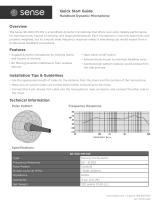
4. Connect the Extension Antennas: The receiver
that connects to the extension antennas is the
primary receiver. Daisy chained receivers will
become replica receivers. Terminators are used
on the last system in the daisy-chain. Up to (4)
8-channel receivers can be daisy chained to form
a 32 channel system. Use ClearOne Remote’s
Antenna Setup Wizard, which opens automatically
the first time you connect. You can also find the
wizard under the SETTINGS tab of the main page
if connecting ClearOne active extension antennas,
make sure the red LED lights up. If not, check the
receiver’s antenna phantom power setting using
the ClearOne Remote Control Software.
5. Connect the analog outputs to the mixer:
The system is shipped with Euroblock connectors. For XLR output SKU’s, there will be Euroblock-to-XLR
adapters included, instead of built-in XLR outputs. The default output level is set to 0 dBu.
Note that factory default for the front panel headphone jack is set for mixed line-level out.
Use ClearOne Remote>Settings>Headphone, to reset for headphones.
CAUTION! Turn off phantom power from the mixer.
Phantom power distorts the audio quality of your microphones.
6. System Test: In most cases, the system is now ready to use. Confirm all channels pass audio perfectly.
Primary
Replica
Terminators
MIC OUTPUTS
4
G
-
+
3
G
-
+
2
G
-
+
1
G
-
+
8
G
-
+
7
G
-
+
6
G
-
+
5
G
-
+
MIC OUTPUTS
4
+
3
+
2
+
1
+
8
+
7
+
6
+
5
+
MIC OUTPUTS
AES
3
50-60
Hz
100-240
VAC
ANTENNA A
ETHERNET
DANTE
ANTENNA B
RS
232
-GPIO
4
G
-
+
3
G
-
+
2
G
-
+
1
G
-
+
8
G
-
+
7
G
-
+
6
G
-
+
5
G
-
+
OUT
IN
PRIMARY
SECONDARY
OUT
IN
IN
OUT
1
2
4
3
MIC OUTPUTS
AES
3
50-60
Hz
100-240
VAC
ANTENNA A
ETHERNET
DANTE
ANTENNA B
RS
232
-GPIO
4
G
-
+
3
G
-
+
2
G
-
+
1
G
-
+
8
G
-
+
7
G
-
+
6
G
-
+
5
G
-
+
OUT
IN
PRIMARY
SECONDARY
OUT
IN
MIC OUTPUTS
AES
3
50-60
Hz
100-240
VAC
ANTENNA A
ETHERNET
DANTE
ANTENNA B
RS
232
-GPIO
4
G
-
+
3
G
-
+
2
G
-
+
1
G
-
+
8
G
-
+
7
G
-
+
6
G
-
+
5
G
-
+
OUT
IN
PRIMARY
SECONDARY
OUT
IN
MIC OUTPUTS
AES
3
50-60
Hz
100-240
VAC
ANTENNA A
ETHERNET
DANTE
ANTENNA B
RS
232
-GPIO
4
G
-
+
3
G
-
+
2
G
-
+
1
G
-
+
8
G
-
+
7
G
-
+
6
G
-
+
5
G
-
+
OUT
IN
PRIMARY
SECONDARY
OUT
IN
IN
OUT

3
Using the ClearOne remote software:
Select the new parameter values and
click “Send Changes to Receiver and
Close”.
Editing Transmitter Parameters:
The easiest and most intuitive way to set the parameters of ClearOne transmitters and receivers is with ClearOne
Remote software. Download the latest software from the ClearOne Resource Library, install and run on a computer
running Windows XP or Windows 7 (32 or 64 bit), and connect to the receiver via USB or RS232. Then open
ClearOne Remote and select ONLINE.
Up to 32 selectable RF channels are available when up to 4 of the WS880 receivers are daisy chained together to
form a system.
(screenshots of the previous software GUI and also screenshots of the new GUI are shown below)
Open The Channel Edit Window:
1. The [Click to Edit] function opens the edit window of the channel you wish to edit.
2. Select the functions you want to edit and enter the parameter. (The various functions are described below.)
Click [OK] to save the changes and close the Channel Edit window.
3. You will notice that the [Needs to Sync] alert is lit. This indicates that one or more parameters are in queue
in the receiver ready to be downloaded and implemented with the next transmitter Sync of the channel.
1)
2)
Click to Edit the
channel’s parameters.
The “Need To Sync” alert is lit. Sync the transmitter
to apply the selected parameters.
3)
Clearone WS800 Remote Software (old):

4
Transmitter + Last 4 digits of serial Number Default Transmitter Preamp Gain
BLT XXXX +10 dB
HH XXXX H18 = 0dB / H13 & H15 = +20dB
PDM XXXX +10dB
BDM XXXX +20dB
Default Transmitter Preamp Gain Settings:
BLT = Beltpack
HH = Handheld Mic
PDM = Gooseneck / Podium Mic
BDM = Tabletop / Boundary Mic
Key:
ClearOne Remote provides the following functions:
1. File: File menu allows the current receiver settings to be saved to a file on your computer or for a previously
saved file on your computer to be recalled to the receiver.
2. Settings:
A. Phantom Power: Turn antenna phantom power on or off. Default = ON.
B. Redundancy: Set adjacent pairs of receivers to redundancy mode. Default = OFF.
C. Headphone Mode: Toggles the mixed output jack from headphone mode to a balanced line output.
Default = Balanced line output.
D. Ethernet Settings: If using Ethernet, assign the proper IP address to the receiver or, enable DHCP.
Default = DHCP enabled.
E. Receiver OLED Dimming: Set the Receiver OLED Display Mode and timer value. Default = Bright when
transmitter is on. Times out after 1 minute.
F. Print Current Settings: Opens print dialog box.
G. Set Receiver Name: label each receiver with a unique name using up to 26 characters.
3. RF Scan - RF Plot: Shows the RF strength of each antenna in a ClearOne system and shows if there is out-
side interference (see Pg. 5).
4. Presets: saves settings to receiver memory or recalls settings from receiver memory. Load “PRESET 1” for
the factory default settings.
5. GPIO: Assign contact closure functions and setup for RS232 control. Default = RS232 enabled.
6. Alerts: Send alerts to authorized personal when preventive maintenance is required of if there is a fault.
Default = none.
7. Help:
A. Tutorials: Setting parameters, Antenna Application Guide, Channel Frequency Assignments, etc.
B. About: Shows vital statistics for each component of the system.
Select the new parameter values and
click “Apply” and Close.
Click to Edit the
channel’s parameters.
The “Need To Sync” alert is lit. Sync the transmitter
to confirm the selected parameters.
1)
2)
3)
WS800 and Dialog20 Remote Software (new):

5
RF Scan and choosing transmitter channels:
1. To run an RF Scan, open the WS800 and Dialog20 Remote Software or the ClearOne WS800 Remote
Software (older version). Screen shots from the older and newer software are shown below.
2. Turn off all of the transmitters.
3. Select “RF Scan” from the tab menu.
4. Press “Start Scan” to begin the scan. Let the scan run for 3 to 5 minutes.
5. Red lines indicate potential interference.
6. Take note of the RF channels with the least amount of interference. A channel with more than -75 dB RF Level
should be avoided.
7. Set the RF channel of the transmitter based on the results of the RF Scan.
8. To set the channel of the transmitter, stop the scan and close the RF Scan Window.
9. Click “Edit” on the slot that you wish to change the channel.
10. An Edit Parameter Window will pop up. Change the channel to the clear channel noted earlier and click
“Apply” to save the changes (On the old GUI click “Send changes to receiver and close”).
11. Sync the transmitter (see Pg. 6).
WS800 and Dialog20 Remote Software (new)
Clearone WS800 Remote Software (old)
Edit Parameter Window
Edit Parameter Window

6
How to sync transmitters with the receiver:
1. Locate the IR (infrared) Sensor on the transmitter.
2. Power on the transmitter.
3. Hold transmitter about 6 inches from the corresponding receiver module with the IR sensor aimed at the
receiver module.
4. Simultaneously press the two buttons on the bottom of the corresponding receiver module to start sending
the IR signal. “SYNCING” shows on the receiver OLED when the IR signal starts. “SYNC OK” shows when
the sync is successful. Repeat the procedure if the receiver display shows “SEARCHING”. It is not necessary
to press any buttons on the transmitter during the procedure. Note: You may get a “SEARCHING” message
if the receiver antennas are not in the same room as the receiver. In this case verify that either the transmitter
display shows “Sync Good” OR the green LED on the transmitter flashes. Also, make sure to dock each
transmitter after syncing to avoid 2 transmitters being synced to the same receiver frequency.
IR
IR
USB
ON / OFF
IR
IR
IR
ON/OFF
IR
USB
How to sync transmitters with the receiver:
NOTE: All transmitters placed in the charging dock will “RF MUTE”.
NOTE: The transmitter and receiver are assigned a new,
random AES 256-bit encryption key every time they are synced.
IMPORTANT: Turn off all transmitters, except the one that is being synced, to
avoid two transmitters being synced to the same receiver frequency.
l
The OLED shows the battery status
The gooseneck or
boundary mic is in use:
The gooseneck battery cassette
is in the docking station:
Hand-held mic or belt-pack
is in the docking station:
How to read the LED:
l
RED = AUDIO MUTE
l
GREEN = AUDIO PASSES
l
BLINKING RED SLOW= BATTERY IS LOW
l
BLINKING GREEN = SYNC SUCCESSFUL
l
RED = CHARGING
l
OFF = FINISHED CHARGING
l
BLINKING RED = CHARGING ERROR
(RE-SEAT TRANSMITTER AND CHECK THE BATTERIES)
The boundary mic is in the
docking station:
l
RED change to AMBER = CHARGING
l
GREEN = FINISHED CHARGING
l
GREEN & RED BLINKING = CHARGING ERROR
(RE-SEAT TRANSMITTER AND CHECK THE BATTERIES)
1.
2.
3.
4.

7
Receiver Module:
1. Antenna Front Mounting Hole: Use back-to-front TNC cables included.
2. Receiver Module (See details below).
3. Mixed audio volume control.
4. USB Port. Connect to computer for ClearOne Remote control. Run software to monitor/edit system
parameters, scan for RF interference and download firmware upgrades.
5. Mixed audio output, 1/4” phone jack for monitoring individual channels or mixed channels.
Note: Factory default for the front panel headphone jack is set for mixed line-level out.
Use ClearOne Remote>Settings>Headphone, to reset for headphones.
6. Power Switch.
ClearOne receiver main-frames hold either four or eight, independent, 24-bit digital audio receiver modules.
There is a front-panel mixed audio output for headphones or direct recording. Each module shares the main-
frame’s two antennas for full-diversity. Receiver main-frames can be daisy-chained together allowing up to
32 channels in an antenna network that shares two antennas. This eliminates the need for external antenna
distribution amps. Main-frames can be connected to form an Ethernet network that monitor and control the
system via a computer. Main-frames also have USB and RS232 connections for serial monitor and control.
IR Sync LED: Sends IR information to SYNC the receiver and transmitter (SYNC pg. 5).
Pressed at the same time: Sends SYNC signal from receiver to transmitter (SYNC pg. 5).
Status LED:
• Green --> The channel is ON and un-muted
• Red --> The channel is OFF
• Flashing Red --> Encryption key mismatch or, two transmitters are synced
to the same Receiver. Solution: Re-sync receiver with transmitter.
• Amber --> The receiver is muted or GPIO is triggered
Modules are designed for quick and easy field replacement for added redundancy.
STAT U S
SELECT
FUNCTION
(SYNC)
IR
FRONT PANEL:
BATTERY
AUDIO
SLOT 3
CH 1
ON
AES256
RF BARS
AUDIO LEVEL
BATTERY LEVEL
CHANNEL NAME
ENCRYPTION
STATUS:
ON = Green
OFF = Red
MUTE = Amber
KEY = Flashing Red (“KEY” = mismatched encryption key)
MODULE:
FREQUENCY
1
2
ANTENNA DIVERSITY
(Colored text indicates status)
1
2
3 4
5 6
1
2
3
4
Receiver:
1
2
&
4
3

8
BACK PANEL WS880 (Euroblock / Phoenix Connector):
1. Antenna A Input: TNC connector for dipole antennas (included), front-to-back antenna cables (included), or
antenna cable to active extension antenna.
2. Antenna A Output: Daisy-chain to the input of another receiver-frame to form an antenna network.
3. Power Cord Input: (Cord with local plug configuration Included). 100-240 VAC, 50/60Hz, 15 W, 250V 320mA slow-
blow fuse (spare included).
4. Ethernet: Connect to a computer or network. Multiple receiver-frames can be daisy-chained together to form a
network.
5. Dante Secondary: Dante Secondary Connection (see pg. 10) (optional feature).
6. Dante Primary: Dante Primary Connection (see pg. 10) (optional feature).
7. GPIO/RS232: This connector combines a General Purpose Input / Output (GPIO) and a RS232 on one DB25
connector. The RS232 can be disabled to add up to 24 GPIO pins.
RS232: The pinout for the RS232 is the standard pinout. Pin 2 on the receiver is transmit, pin 3 is receive, and pin
7 is ground. Most computers now use a DB9 connector for RS232. The standard off-the-shelf DB9 to DB25 cable
will work. This cable swaps pins 2 and 3 internally. If you computer has a DB25 connector for RS232, use a straight
DB25 to DB25 cable. Do not use a null modem cable.
GPIO: GPIO acts like a contact closure. Use ClearOne Remote to assign an event that toggles the GPIO pin.
The factory default toggles pins X through X to correspond to muting a receiver module. ClearOne Remote has a
feature that lets you assign how the system responds to a transmitter mute (see ClearOne Remote).
A. Mute the channel’s receiver audio (Factory default).
B. Toggle the GPIO but do not mute the receiver audio. Use this with automated mixers or echo cancelling DSPs.
C. Mute the channels receiver audio and toggle the GIPO pin.
8. DC Input: Optional external DC power source eliminates the need for AC input or, can be used as a redundant,
back-up power source.
9. Audio Output Jacks: Configured for four or eight-module receiver frames. Phoenix Euroblock connectors are
standard (Euroblock-to-XLR adapters are optional).
10. Antenna B Input: TNC connector for dipole antennas (included), front-to-back antenna cables (included), or
antenna cable to active extension antenna.
11. Antenna B Output: Daisy-chain to the input of another receiver-frame to form an antenna network.
BACK PANEL WS840 (Euroblock / Phoenix Connector):
Receiver Back:
1
5 6
2 3 4
7
9
11
10
8
1
5 6
2 3 4
7
9
11
10
8
For the XLR output option, the analog audio outputs will use a Euroblock-to-XLR adapter.
Euroblock to XLR Adapter:
WIRE LENGTH
152
5 (mm)
25 ± 1
1
12
P1
P2
P3
P4
P5
(mm)

9
1. Heads: Three (3) choices of microphone capsules are available:
H-13 (dynamic, super cardioid for performance)
H-15 (dynamic cardioid for performance)
H-18 (condenser cardioid for conferencing)
Condenser heads are more “transparent” and do not require the microphone to be held as close to the mouth.
2. Display: OLED display is used to program and display the current status of the transmitter functions.
3. Switch: User programmable to toggle on/off, on/mute/ or on/on.
4. Battery and Control Cover: Unscrew counter-clockwise and gently slide open.
5. Antenna Cover: Do not hold the antenna cover. Your hand will shield the RF signal and cause poor audio
performance.
6. IR Sensor Port: The IR sensor is used to transfer channel settings and a random encryption key from the
receiver to the transmitter.
7. Select button: Press this button to select a function. The first press activates the first edit able function in the
tree. Press again to move to the next edit able function.
8. Parameter Up: Press this button to increase the value of the selected function.
9. Parameter Down: Press this button to decrease the value for the selected function.
10. USB Port: Plug a micro USB cable into the USB port to charge the batteries or upgrade the firmware.
11. Batteries: (not shown) AA NiMH, 2500-mAh or greater is recommended.
12. Battery Door: Open position.
1. Antenna: Length and style varies with the transmitters model number. Antennas are field replaceable to
improve reliability and redundancy.
2. Programmable Switch: Toggle on/off, on/mute/ or on/on.
3. Microphone Connector: TA4 mini XLR style: ClearOne offers a full range of lavaliere and headset mics for
optimal performance of your ClearOne transmitter. Works with both snap in and screw-in microphones.
4. Display: OLED display is used to program and display the current status of the transmitter functions.
5. IR Sensor Port: The IR sensor is used to transfer channel settings and a random encryption key from the
receiver to the transmitter.
6. Select: Press this button to select a function. The first press activates the first edit able function in the tree.
Press again to move to the next edit able function.
7. Parameter Down: Press this button to decrease the value for the selected function.
8. Parameter Up: Press this button to increase the value of the selected function.
9. Batteries: AA NiMH, 2500-mAHr or greater is recommended.
10. Battery Door Locks: To open, press both at the same time and lift the door open. To close, snap the door closed.
11. USB Port: Plug a micro USB cable into the USB port to charge the batteries or upgrade the firmware.
12. Belt-Clip: Spring-loaded clip for attaching the transmitter to a belt or similar object. Spring pressure presses
the clip into two holes in the transmitter body. Pull them out to remove or reverse the clip. Exercise caution to
prevent injury or scratching the case.
13. Contacts: Charging contact points for the docking station.
HAND-HELD MICROPHONE:
BELT PACK:
Transmitters:
1
2
3
4
4
7
6
8
9
10
11
12
6
8
9
s
1
9
5
2
3
6
7
8
4
10
10
11
12
13
13
7

10
1. Power LED: When the Table Mic is on, the LED signals:
Red = audio mute.
Green = audio passes.
Blinking Red = battery low.
Blinking Green = sync successful.
2. Contacts: Contact points for the charging station.
3. I/R Sensor: Inputs programming instructions and encryption
key from the receiver.
4. Power Switch: On / Off.
5. USB Port: Doubles as the power supply / recharger
connection and computer programming port. The
transmitter operates normally under USB power, with dead
or no batteries for permanent installations.
The ClearOne WS800 Table-top Microphone combines the professional audio specs and security of a wired mic
with wireless convenience. Available in omni or cardioid polar pick-up patterns with 265-bit FIPS 197 encryption.
ClearOne Gooseneck Podium Mic Stems are available in 6”, 12” and 18”
lengths that are interchangeable and field replaceable.
The Gooseneck mic capsule is available with a cardioid polar pattern.
1. Interchangeable microphone capsule.
2. Flexible stem section.
3. A 4-pin XLR connector allows the exchange of different length
microphone stems.
TABLE-TOP MICROPHONE:
PODIUM GOOSENECK STEM :
GOOSENECK MIC CAPSULE:
CARDIOID
pickup pattern
Transmitters:
1
3 2 2
OFF/ON
IR
USB
2
3 4
5
2
1
Capsules are field replaceable.

11
1. ClearOne Capsules: Cardioid polar pattern.
2. Goosenecks: Two flexible sections to extend over a laptop or briefcase. Available
in 6, 12, and, 18 inch lengths.
3. Radio-transparent ABS Top: Stylish design that hides and protects the antenna.
4. Cast Metal Bottom: Zinc base bottom adds stability and absorbs desk noise.
5. Power LED: (see fig. 2 below)
6. Button Programming Options:
1) press to talk.
2) press to mute.
3) toggle on or off.
7. Power Switch Programming Options:
1) On / Off.
2) On / Mute.
3) On / On.
8. I/R Sensor: Inputs programming instructions and encryption key from the
receiver.
9. USB Port: Doubles as the USB recharger connection and computer programming
port. The transmitter operates normally under USB power, with dead or no
batteries for permanent installations. When charging using the USB Port,
when the LED signals: RED = Charging / OFF = finished charging.
10. Battery Cassette: Pull tab to remove the battery cassette. Recharge the batteries
by inserting the cassette into the ClearOne Charging Dock. (See figure 1 below)
The battery cassette holds four, off-the-shelf, AA, NiMH batteries for up to 9.5 hours
continuous usage per charge.
11. Keyholes: For permanent mounting
12. Rubber Feet: Absorb desk noise and provide a stable, non-skid base.
(Figure 1) (Figure 2)
Recharge the batteries by
inserting the cassette into the
ClearOne Charging Dock.
RED = Audio Mute
GREEN = Audio Passes
BLINKING RED = Battery Low
BLINKING GREEN = Sync
Successful
When the Gooseneck Mic is in use, the
LED signals:
PODIUM GOOSENECK:
The ClearOne Podium microphone combines the professional audio specs
and security of a wired mic with wireless convenience. For use with battery
power or permanently install the microphone using USB power.
Transmitters:
5
6
2
3
4
1
8
7
9
11
10
12

12
DANTE:
Dante Output option for ClearOne WS800 wireless receivers:
The Dante option for WS800 series wireless microphone receivers adds networked digital audio output to the receiver audio
output options. Each receiver slot is assigned an output channel on the installed Dante output card. These digital audio
streams can then be routed to any Dante input devices using the Dante Controller software application, shown below.
The Dante card comes pre installed in the WS800 receiver. There are 2 RJ-45 jacks on the rear panel of the
WS800 receiver used to connect the Dante card to the network. They are labelled ‘Primary’ and ‘Secondary’.
The Primary is used for the main network connection, and the Secondary can be used as a redundant backup
connection.
The Dante card is configured with each receiver slot assigned to a single Dante output channel. Slot 1 is
assigned to output 1; slot 2 is assigned to output 2, etc. The Dante connection is always active, so simply
connect the Ethernet cable to the Primary RJ-45 jack and use Dante Controller to route the signal.
IN
AES3
IN
50-60 Hz 100-240 VAC
ANTENNA A
ETHERNET
WORD CLOCK
ANTENNA B
RS
232-GPIO
Made In USA
IN
OUT
OUT
OUT
MIC OUTPUTS
1
2
34
IN
AES3
IN
50-60 Hz 100-240 VAC
ANTENNA A
ETHERNET
WORD CLOCK
ANTENNA B
RS
232-GPIO
Made In USA
IN
OUT
OUT
OUT
MIC OUTPUTS
1
2
34

13
RF Exposure Information
The transmitters have been tested and have been shown to be compliant for localized specific absorption rate (SAR)
for uncontrolled environment/general exposure limits specified in ANSI/IEEE Std. C95.1-1992 and have been tested in
accordance with the measurement procedures specified in IEEE 1528-2003 and IEC 62209-2.
RF Compliance Information
The transmitters have been tested and have been shown to meet CE spectral bandwidth requirements at 1 mW and 10 mW
output power.
This equipment may be capable of operating on some frequencies and at some RF power levels not authorized in your
region. Please contact your national authority to obtain information on authorized frequencies and RF power levels for
wireless microphone products in your region.
This product meets the Essential Requirements of all relevant European directives and is eligible for CE marking.
Uncompressed transmitters:
BELTPACK
FCC: FBIBELTPACK
IC: 1970A-BELTPACK
BELTPACK
FCC: RBODS80T
IC: 8240A-DS80T
GOOSENECK
FCC: RBODS80P
IC: 8240A-DS80P
HANDHELD
FCC: RBODS80H
IC: 8240A-DS80H
TABLETOP
FCC: RBODS80C
IC: 8240A-DS80C
Compressed transmitters:
GOOSENECK
FCC: FBIGOOSENECK
IC: 1970A-GOOSENECK
HANDHELD
FCC: FBIHANDHELDMIC
IC: 1970A-HANDHELDMIC
TABLETOP
FCC: FBITABLETOP
IC: 1970A-TABLETOP
Certified under FCC Part 74 and FCC Part 15.
Certified by IC in Canada under RSS-123, RSS-102 and RSS-210.
Available frequencies:
M915: 902 MHz to 928 MHz (C, U)
M715: 710 MHz to 740 MHz (C, U)
M610: 603 MHz to 630 MHz (C, U)
Exposure and Compliance:
M500: 486 MHz to 512 MHz (C)
M586: 573 MHz to 599 MHz (C)
M800: 793 MHz to 819 MHz (C)
M930: 917 MHz to 943 MHz (C)
(C = Data Compression, U = No Data Compression)
Check with your local radio authorities for allowable frequencies and maximum transmit power.
Modifications (FCC 15.21)
Changes or modifications to this equipment not expressly approved by ClearOne may void the user’s authority to operate
this equipment.
This device complies with Industry Canada licence-exempt RSS standard(s). Operation is subject to the following two con-
ditions: (1) this device may not cause interference, and (2) this device must accept any interference, including interference
that may cause undesired operation of the device.
Applies to WS80-T:
Under Industry Canada regulations, this radio transmitter may only operate using an antenna of a type and maximum (or
lesser) gain approved for the transmitter by Industry Canada.
To reduce potential radio interference to other users, the antenna type and its gain should be so chosen that the equivalent
isotopically radiated power (e.i.r.p.) is not more than that necessary for successful communication.
This radio transmitter (WS80-T) has been approved by Industry Canada to operate with the antenna types listed below
with the maximum permissible gain and required antenna impedance for each antenna type indicated. Antenna types not
included in this list, having a gain greater than the maximum gain indicated for that type, are strictly prohibited for use with
this device.
Monopole antenna, 0dbi gain, 50 ohm impedance.
Le présent émetteur radio (WS80-T) a été approuvé par Industrie Canada pour fonctionner avec les types d’antenne
énumérés ci-dessous et ayant un gain admissible maximal et l’impédance requise pour chaque type d’antenne. Les types
d’antenne non inclus dans cette liste, ou dont le gain est supérieur au gain maximal indiqué, sont strictement interdits pour
l’exploitation de l’émetteur.
France:
Le présent appareil est conforme aux CNR d’Industrie Canada applicables aux appareils radio exempts de licence.
L’exploitation est autorisée aux deux conditions suivantes : (1) l’appareil ne doit pas produire de brouillage, et (2)
l’utilisateur de l’appareil doit accepter tout brouillage radioélectrique subi, même si le brouillage est susceptible d’en com-
promettre le fonctionnement.
Clearone Wireless Receivers, Transmitters, and, Antennas are intended for indoor use only.

North America
Tel: 801-975-7200
Toll Free: 800-945-7730
Sales: 800-707-6994
Fax: 801-977-0087
Europe & Oceania
Tel: +44 (0) 1189 036 053
Asia Pacific
Tel: +852 3590 4526
Latin America
Tel: 801-974-3621
Middle East
Tel: +852 3590 4526
Other product names may be registered trademarks of their respective owners who do not necessarily endorse ClearOne or ClearOne’s products. All rights reserved. Information in
this document subject to change without notice. © 2016 ClearOne. LIT-CO-RCVR-OP-EN v10.0 August. 2017
Korean Compliance (KCC):
Class A (Broadcasting and Communication Equipment for Business):
Sellers and users note that this equipment is an electromagnetic devise for business (class A), and this is
for using in the outside of house.
KCC Certificate ID’s Model Numbers and Part Numbers:
# KCC Certificate ID WS800 Model Number WS800 Products with M930 RF Range Part Numbers
1 MSIP-RMM-FBI-WS880C
WS840XD 4 Channel Receiver 910-6000-407-X-C-D
WS840X 4 Channel Receiver 910-6000-407-X-C
WS840CD 4 Channel Receiver 910-6000-407-C-D
WS840C 4 Channel Receiver 910-6000-407-C
WS880XD 8 Channel Receiver 910-6000-807-X-C-D
WS880X 8 Channel Receiver 910-6000-807-X-C
WS880CD 8 Channel Receiver 910-6000-807-C-D
WS880C 8 Channel Receiver 910-6000-807-C
2 MSIP-CRM-FBI-M930-BP M930-BP Beltpack Transmitter 910-6004-007-C
3 MSIP-CRM-FBI-M930-GS M930-GS6
Gooseneck Transmitter w/6” neck 910-6002-067-C
Gooseneck Transmitter w/12” neck 910-6002-127-C
Gooseneck Transmitter w/18” neck 910-6002-187-C
4 MSIP-CRM-FBI-M930-HH-C M930-HH-C
Handheld Transmitter - Cardioid 910-6003-007-C
Handheld Transmitter - Super Cardioid 910-6003-017-C
Handheld Transmitter - Hyper Cardioid 910-6003-027-C
5 MSIP-CRM-FBI-M930-TB-C M930-TB-C
Tabletop Transmitter - Cardioid 910-6001-007-C
Tabletop Transmitter - Omni 910-6001-017-C
Product Serial Number Reference:
A급 기기 (업무용 방송통신기자재):
이 기기는 업무용(A급)으로 전자파적합기기로서판매자 또는 사용자는 이 점을 주의하시기 바라며, 가정 외의 지역에서 사용하는 것을 목적으로 합니다.
SSSS-YYWW-CMJJJ
SEQUENCE #
YEAR
WEEK
CONTRACT MANUFACTURER CODE
JOB # OR LOT # (IF APPLICABLE)
NOTE: USUALLY BLANK
/