Page is loading ...
Page is loading ...

en
Ú
Installation instructions
Safety precautions
Read the appliance instructions before installing and using.
The graphics in these Assembly instructions are given as a
guide only.
The manufacturer is exempt from all liability if this manual's
requirements are not complied with.
All operations relating to installation, regulation and
conversion to other gas types must be carried out by an
authorised installation engineer, respecting all applicable
regulations, standards and the specifications of the local gas
and electricity providers.
You are recommended to contact the Technical Assistance
Service to convert to another gas type.
Before you begin, turn off the appliance's electricity and gas
supply.
This appliance has been designed for home use only, not for
commercial or professional use. This appliance cannot be
installed on yachts or in caravans. The warranty will only be valid
if the appliance is used for the purpose for which it was designed.
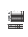
Before installing, check that local distribution conditions (gas
type and pressure) and the appliance's adjustment are
compatible (see table I). The appliance's adjustment conditions
are written on the label or the specifications plate.
This appliance can only be installed in a well-ventilated place in
accordance with existing regulations and ventilation
specifications. The appliance must not be connected to a
combustion product removal device.
The supply cable must be attached to the unit to prevent it from
touching hot parts of the oven or hob.
Appliances with electrical supply must be earthed.
Do not tamper with the appliance's interior. If necessary, call our
Technical Assistance Service.
Before installing
This appliance is class 3 type, according to the EN 30-1-1
regulation for gas appliances: built-in appliance.
These individual appliances can be combined with other
identical appliances and/or with conventional hobs of the same
make, using the joint accessory. See the catalogue for details.
The units next to the appliance must be made of non-flammable
materials. The laminated covering and glue for adhering it must
be heat resistant.
This appliance cannot be installed above fridges, washing
machines, dishwashers or similar.
An oven must have forced ventilation to install a hob above it.
Check the dimensions of the oven in the installation manual.
If an extractor fan is installed, you must follow the installation
manual's instructions, always keeping a minimum distance of
650 mm to the hob.
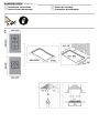
Preparation of the kitchen unit (fig. 1-2)
Make an appropriate size cut in the work surface.
If the hob is electric or mixed (gas and electricity) and there is
no oven below, place a non-flammable separator (e.g. metal or
plywood) 10 mm from the bottom of the hob. This will prevent
access to the base of the hob.If the hob is gas, it is
recommendable to place the separator at the same distance.
On wood work surfaces, varnish the cutting surfaces with a
special glue. This protects them from moisture which could
collect under the work surface.
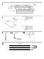
Installation of appliance (fig. 3)
Note: Wear protective gloves to fit the hob.
The clips and adhesive seal (underside of the hob) are factory-
fitted: Do not remove these under any circumstances: The
adhesive seal prevents water seepage.
In order to fit the appliance into the kitchen unit, first place the
hob in the correct position then loosen each of the clips so that
they all turn freely (it is not necessary to completely undo them).
Insert and centre the hob.
Press the sides of the hob until it is supported around its entire
perimeter.
Turn the clips and tighten them fully. Fig. 3.
Removal of hob
Turn off the appliance's electricity and gas supply.
Unscrew the clips and proceed in the reverse order to
installation.
Gas connection (fig. 4)
The gas connection must be located in a position where the
stop tap is accessible.
The end of the inlet connection point of the gas hob has a 1/2”
thread (20.955 mm) that allows for:
■ A fixed connection.
■ Connection using a flexible pipe (L min. 1 m - max. 3 m).
In this case, it is necessary to insert the accessory (427950)
and the watertight seal (034308) supplied between the manifold
outlet and the gas supply. Fig. 4a.
D

You must prevent the pipe from coming into contact with
moving parts of the kitchen unit (for example, a drawer) and
prevent access to any spaces which might become obstructed.
If you need to connect the gas supply horizontally, our technical
assistance service can supply you with an L-tube
(code 173018), and a seal (code 034308).
Do not move the L-tube from the factory-fitted position,
regardless of the connection type.
If you need to make a cylindrical connection, connect directly to
the manifold outlet. Fig. 4b.
Please remember to insert the seal.
: Danger of leaks!
If any connection is handled, check the seal.
The manufacturer is not liable for any connection leaking, after
being handled.
Electric connection (fig. 5)
Check that the voltage and power of the appliance are
compatible with the electrical installation.
The hobs are supplied with a power cable with or without a wall
socket plug.
Appliances with plugs must only be connected to sockets that
have earth wires correctly installed.
Provide an omnipolar cut-off switch with a minimum contact
opening of 3 mm (except for plug connections, if the user has
access to it).
This appliance is type “Y”: the supply cable can only be
changed by the Technical Assistance Service and not the user.
The cable type and minimum cross-section must be respected.
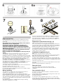
Changing the gas type
If the country's regulations allow, this appliance can be adapted
to other types of gas (see specifications plate). The components
required for this are in the transformation kit supplied
(depending on the model) or are available from our Technical
Assistance Service. The following steps should be taken:
A) Changing the nozzles (fig. 6-6a):
1. Remove the pan supports, burner caps and diffusers.
2. Change the nozzles using the spanner code 340847 (code
340808 for double-flame burners or triple-flame burners)
provided by our Technical Assistance Service, see table II,
taking special care to ensure that the nozzle does not fall
when it is removed from or fitted to the burner.
Ensure that it is completely tightened in order to guarantee the
seal.
Primary air adjustment is not necessary with these burners.
3. Position the diffusers and burner caps on the corresponding
rings and the pan supports on their fasteners.
B) Adjusting the taps
1. Set the control knobs to minimum.
2. Remove the control knobs from the taps. Fig. 7.
It has a flexible rubber valve reinforcing ring. Simply press on
this seal with the tip of a screwdriver to allow access to the tap
adjusting screw. Never remove the valve reinforcing ring.
3. Adjust the minimum ring setting by turning the by-pass screw
using a flat head screwdriver.
Depending on the gas to which your appliance is going to be
adapted, see table III, carry out the corresponding action:
A: firmly tighten the by-pass screws.
B: loosen the by-pass screws until the gas flow from the
burners is correct: when adjusting the control knob between
maximum and minimum, the burner does not go out, nor is
there a flame backdraught created.
C: the by-pass screws need to be changed by an authorised
engineer.
D: do not touch the by-pass screws.
All valve reinforcing rings must be in position to ensure
watertightness. These devices are essential for the correct
operation of the appliance as they prevent liquids and dirt from
entering the appliance.
Refit the control knobs.
Never remove the tap spindle (Fig. 8). In the event of a
malfunction, change the whole tap.
Caution!
After finishing, the sticker indicating the new type of gas must be
placed close to the specifications plate.
es
Û
Instrucciones de montaje
Indicaciones de seguridad
Lea las instrucciones del aparato antes de proceder a su
instalación y uso.
Los gráficos representados en estas instrucciones de montaje
son orientativos.
El fabricante queda exento de toda responsabilidad si no se
cumplen las disposiciones de este manual.
Todos los trabajos de instalación, regulación y adaptación a
otros tipos de gas deben ser efectuados por un técnico de
instalación autorizado, respetando toda la normativa y
legislación aplicables, y las prescripciones de las compañías
locales proveedoras de gas y electricidad.
Se recomienda llamar a nuestro Servicio Técnico para la
adaptación a otros tipos de gas.
Antes de cualquier actuación corte la alimentación eléctrica y
de gas del aparato.
Este aparato ha sido diseñado solo para uso doméstico, no
estando permitido su uso comercial o profesional. Este aparato
no puede ser instalado en yates o caravanas. La garantía
únicamente tendrá validez en caso de que se respete el uso
para el que fue diseñado.
Antes de la instalación, debe comprobar que las condiciones
de distribución local (naturaleza y presión del gas) y el reglaje
del aparato son compatibles (ver tabla I). Las condiciones de
reglaje del aparato están inscritas sobre la etiqueta o la placa
de características.
Este aparato solo puede ser instalado en un lugar bien
ventilado, respetando los reglamentos en vigor y las
disposiciones relativas a la ventilación. No debe conectarse el
aparato a un dispositivo de evacuación de los productos de
combustión.
El cable de alimentación debe fijarse al mueble para evitar que
toque partes calientes del horno o placa de cocción.
Los aparatos con alimentación eléctrica deben conectarse a
tierra obligatoriamente.
No manipule el interior del aparato. Si es preciso, llame a
nuestro Servicio Técnico.
Antes de la instalación
Este aparato corresponde a la clase 3, según la norma EN 30-
1-1 para aparatos a gas: aparato encastrado en un mueble.
Estos aparatos pueden ser combinados entre sí, y/o con placas
de cocción convencionales de la misma marca, utilizando el
accesorio de unión. Consulte catálogo.
Los muebles próximos al aparato deben ser de materiales no
inflamables. Los revestimientos estratificados y la cola que los
fija deben ser resistentes al calor.
Este aparato no se puede instalar sobre neveras, lavadoras,
lavavajillas o similares.
Para instalar la placa de cocción sobre un horno, este debe
tener ventilación forzada. Compruebe las dimensiones del
horno en su manual de instalación.
Si se instala un extractor, debe tenerse en cuenta su manual de
instalación, respetando siempre una distancia vertical mínima
de 650 mm a la placa de cocción.
Preparación del mueble (fig. 1-2)
Haga un corte de las dimensiones necesarias en la superficie
de trabajo.
Si la placa de cocción es eléctrica o mixta (gas y electricidad) y
no hay un horno debajo, coloque un separador de material no
inflamable (p. ej. metal o madera contrachapada) a 10 mm de
la base de la placa de cocción. Así impide el acceso a la parte
inferior de esta. Si la placa de cocción es de gas, se
recomienda colocar el separador a la misma distancia.
En superficies de trabajo de madera, barnice las superficies de
corte con una cola especial para protegerlas de la humedad.
Instalación del aparato (fig. 3)
Nota: Usar guantes de protección al instalar la placa.
Las grapas y la junta adhesiva (borde inferior de la placa de
cocción) salen puestas de fábrica. No las quite bajo ningún
concepto. La junta adhesiva evita filtraciones.
Para la fijación del aparato al mueble de encastramiento,
deberá, una vez colocada la placa de cocción en su posición
de trabajo, desatornillar cada una de las grapas hasta que
estas giren libremente (no es necesario el desatornillado total).
Encastre y centre la placa de cocción.
Page is loading ...
Page is loading ...
Page is loading ...
Page is loading ...
Page is loading ...
-
 1
1
-
 2
2
-
 3
3
-
 4
4
-
 5
5
-
 6
6
-
 7
7
-
 8
8
-
 9
9


Ask a question and I''ll find the answer in the document
Finding information in a document is now easier with AI
in other languages
- français: Bosch PSB326B21E/24 Manuel utilisateur
- español: Bosch PSB326B21E/24 Manual de usuario
- português: Bosch PSB326B21E/24 Manual do usuário
Related papers
-
Bosch PRW926B20T/40 Installation guide
-
-
-
-
Bosch ER326BB90N/02 User manual
-
Bosch PRS926B70N/40 User manual
-
Bosch POP616B81E Owner's manual
-
Bosch PBH615B90E Owner's manual
-
-
Bosch PCQ875B11E User manual
Other documents
-
Siemens ET13051W/01 User manual
-
-
Siemens EC915WB90W/01 User manual
-
-
-
V-ZUG 798 Installation guide
-
-
-
-
Teka GBC 75030 User manual