
real world solutions for storage networking
1·888·AT·VIXEL / www.vixel.com
Vixel HQ / 11911 North Creek Parkway South / Bothell, WA 98011 / USA
tel 425 806 5509 / fax 425 806 4050
Vixel Europe / P.O. Box 261 / Great Missenden / England / HP16 0XX
tel 011 44 1494 890666 / fax 011 44 1494 863331
Vixel Asia Pacific / 11911 North Creek Parkway S / Bothell, WA 98011 / USA
tel 626 858 2430 / fax 626 915 0759
Vixel China / Beijing, China / tel 10 6849 9547 / fax 10 6849 9544
All names and trademarks are the property of their respective owners. © 2001 Vixel Corporation.
All Rights Reserved. Contents subject to change. 00041235-001 Rev. A
Managed Storage Switch
InSpeed Model 335
INSTALLATION&CONFIGURATIONguide
™

Part Number 00041363-001 Rev. A i
Copyright © 2003 Vixel Corporation. All rights reserved worldwide. No part of this
document may be reproduced by any means nor translated to any electronic medium
without the written consent of Vixel Corporation.
Information furnished by Vixel Corporation is believed to be accurate and reliable.
However, no responsibility is assumed by Vixel Corporation for its use; or for any
infringements of patents of other rights of third parties which may result from its use.
No license is granted by implication or otherwise under any patent or patent rights of
Vixel Corporation.
Vixel and InSpeed™ are registered trademarks of Vixel Corporation. All other brand or
product names referenced herein are trademarks or registered trademarks of their
respective companies or organizations.
Vixel Corporation provides this manual “as is,” without any warranty of any kind,
either expressed or implied, including but not limited to the implied warranties of
merchantability or fitness for a particular purpose. Vixel Corporation may make
improvements and changes to the product described in this manual at any time and
without any notice. Vixel Corporation assumes no responsibility for its use, nor for any
infringements of patents or other rights of third parties that may result. Periodic changes
are made to information contained herein; although these changes will be incorporated
into new editions of this manual, Vixel Corporation disclaims any undertaking to give
notice of such changes.
Vixel Corporation, 11911 North Creek Parkway South, Bothell, WA 98011

ii
Table of Contents
1 Introduction................................................................... 1
2 Installation..................................................................... 3
3 Management................................................................ 11
4 Technical Reference...................................................... 54
Appendixes ............................................... 57
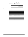
A Specifications .............................................................. 58
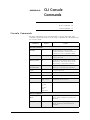
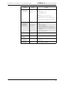
B CLI Console Commands............................................. 60
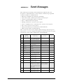
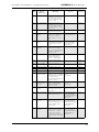
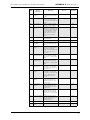
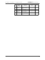
C Event Messages........................................................... 63
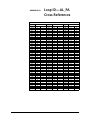
D Loop ID—AL_PA Cross References ............................ 67
E Glossary...................................................................... 68
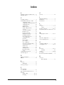
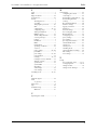
Index .................................................................................. 70

1
CHAPTER 1 Introduction
About This Guide
This guide is designed to provide the user with the necessary information to install the
Vixel Model 335 Switch and associated Small Form-Factor Pluggable Transceivers
(SFPs) for use in Fibre Channel applications in typical Storage Area Networks (SANs).
Overview
The twelve-port switch provide 1 or 2 Gigabit per second (Gb/s) Fibre Channel support
and the flexibility of SFP-based design in a 1U full-rack size. The switch is designed as a
twelve-port central interconnect for Fibre Channel applications and supports the ANSI
FC-AL standard.
Note: Nodes include host
computers, servers, and
storage arrays.
Devices are connected to the switch through Small Form-factor Pluggables (SFPs)
transceivers and cables. Each attached node has 1 or 2 Gigabit-per-second (Gb/s) of
available bandwidth; however, all ports must be set to the same speed. Ports with no
inserted SFPs or with inoperative nodes are bypassed. The switch’s LED indicators
provide status information to service personnel to indicate whether the port is active or
bypassed.
Features
The switch incorporates the following features:
• InSpeed™ Technology
• Operating speeds of either 1.0625 or 2.125 Gb/s.
• Standard 1U size for easy installation into standard rack or placement on a tabletop.
• Twelve SFP ports for total cabling flexibility and scalability.
• Management through the switch’s integrated web server or command line interface
(CLI).
• 10BaseT Ethernet and RS-232 Serial ports on the switch.
• Switching and non-switching operating modes.
• System and port status LED indicators
• Auto-sensing, universal power supply supporting 100 to 250 VAC and 50 or 60 Hz.
About This Guide 1
Overview 1
Features 1
Fibre Channel-Arbitrated Loop 2
InSpeed™ Technology 2
Important safety, electromagnetic compatibility, and regulatory information is
contained in the guide titled Safety & Regulatory Guide. The installation and use of
this product must be in accordance with the information given in that guide.

Vixel Model 335 Installation & Configuration Guide CHAPTER 1 Introduction
2
Fibre Channel-Arbitrated Loop
The Fibre Channel-Arbitrated Loop (FC-AL) is an ANSI standard (X3T11) designed to
provide shared bandwidth over low-cost media. Early adopters primarily use the SCSI
protocol transported over Fibre Channel for distributed server and storage cluster
applications. The switch is a central point of interconnect designed to maintain a fault-
tolerant physical loop topology.
InSpeed™ Technology
Vixel’s InSpeed™ technology enables the switch’s router to properly utilize the switch
core in sending data from one port to another. This process allows for multiple,
simultaneous conversations between ports — effectively multiplying bandwidth. Using
an advanced switching architecture that couples a non-blocking crossbar switch with
unique port logic and per-port SERDES', the InSpeed™ technology creates the industry’s
highest-density Fibre Channel switch.
This technology provides the same performance as switches that support FC-SW2, while
solving the latency problems associated with large FC-AL loops. During initialization,
InSpeed™ connects all devices together in a standard FC-AL2 loop. Upon completion of
the initialization process, InSpeed™ transitions to switching mode. When arbitration is
attempted, InSpeed™ analyzes connections and routes traffic directly to the destination
port.
The InSpeed™ switch is bufferless and operates on only the lower seven bits of the full
Fabric address field. Aside from the time it takes to complete a LIP sequence, the switch
operates at full switching bandwidth that reaches wire speeds of 200 MB/s.

3
CHAPTER 2 Installation
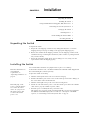
Unpacking the Switch
To unpack the switch:
1. Inspect the outer shipping container for any damage that may have occurred in
shipping and report any sign of damage to the appropriate shipping agency.
2. Remove the switch from the shipping container; save the shipping container, foam,
and anti-static bags—returning the switch in any other container or packing material
may void its warranty.
3. Inspect the switch thoroughly. (If any signs of damage are seen, notify your sales
representative and/or the shipping agency.)
Installing the Switch
You can install the switch into an equipment rack or place it on a desktop.
Note: For information on
environmental
requirements, see
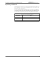
“Operating Conditions” on
page 59.
To mount the switch in a rack, consult the installation documentation that shipped with
the rack-mounting kit (ordered separately).
To place the switch on a desktop:
1. Turn the switch upside down so the case bottom is facing up.
2. Install a self-adhesive pad on each corner of the switch (prevents surface damage) at
the corner marks on the switch underside.
3. Turn the switch right side up so the case bottom is facing down.
Note: The plug on the
power cord is intended to
serve as the disconnect
device. To cycle power to
the switch, remove and
reconnect the switch’s
power cord.
4. Attach one end of the switch’s power cord to the switch’s power inlet socket and the
other end to a properly earthed receptacle (outlet).
5. Insert the power cord firmly into the power inlet socket.
The switch is now powered on. The switch automatically executes a Power-On Self
Test (POST) and its LEDs display the test results (for a description of the POST
sequence, see “Performing a Power On Systems Test” on page 4).
Unpacking the Switch 3
Installing the Switch 3
Using Small Form-Factor Pluggable (SFP) Transceivers 4
Performing a Power On Systems Test 4
Setting Up the Switch 5
Attaching Devices 5
Understanding the Switch’s LEDs 6
Cascading Switches 9

Vixel Model 335 Installation & Configuration Guide CHAPTER 2 Installation
4
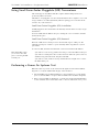
Using Small Form-Factor Pluggable (SFP) Transceivers
The switch supports any SFP module that complies with the SFP specification as
produced by MSA consortium.
The SFPs are “hot-pluggable” into the switch which allows host computers, servers and
storage modules to be added dynamically without requiring power removal from the
switch or any connected devices.
Small Form-Factor Pluggable (SFP) Installation
An SFP plugged into the switch will be automatically inserted when it is ready to begin
initialization.
To insert an SFP, slide the SFP into the port, ensuring the correct orientation, until the
latch clicks into place.
Small Form-Factor Pluggable (SFP) Removal
Removal of SFPs from a switch port causes the automatic bypass of that port. The
remaining switch ports continue to operate normally with no degradation of system
performance.
To extract an SFP, determine first what kind of extraction mechanism the SFP has.
Note: Most SFPs require
you to remove the cable
prior to removing the SFP
from the port.
If the SFP has a removal tag, pull the removal tag to extract the SFP from the port.
If the SFP has a small plastic slider on the bottom side under the optical connector,
simultaneously push in the slider and pull out the SFP.
If the SFP has a bale (small metal clasp), unlatch the bale and pull on it to extract
the SFP from the port.
Performing a Power On Systems Test
When the switch is powered on, the switch runs through Power-On Self Test (POST)
diagnostics to verify the fundamental integrity of the switch box.
1. All switch LEDs turn on (LEDs illuminate) for approximately two seconds during
power on, then all LEDs—except for the Power LED—turn off (LEDs extinguish).
2. If the port bypass LEDs are blinking at a constant rate and the Switch Fault LED is
on, the switch has detected a hardware fault—contact an authorized service person.

Vixel Model 335 Installation & Configuration Guide CHAPTER 2 Installation
5
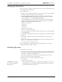
Setting Up the Switch
Before the switch can establish communication with your network, its IP Address needs
to be changed from its default value.
To set the IP Address:
1. Attach one end of an RS-232 null modem cable to the serial port on the workstation;
attach the other end to the RS-232 port on the switch.
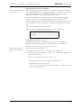
2. For Unix workstations, type the following command at a Unix prompt (where
SerialPortDevicePath is the filepath to the serial port used for connection):
cu -s 19200 -b 8 -1 SerialPortDevicePath
For Windows® platforms, open a terminal session through a terminal emulation
program (such as HyperTerminal) with the appropriate serial port (for example,
COM1) and the following serial port parameters:
• Bits per second: 19200
• Data bits: 8
• Parity: None
• Stop bits: 1
• Flow control: Xon/Xoff
You are now connected to the CLI.
3. To log onto the CLI, type li at the prompt, then type the password (the default pass-
word is password).
4. To change the switch’s IP parameters, type co and then type 1 to change the switch’s
IP address.
5. If you want to change the switch’s netmask and default gateway, type 2 and 3,
respectively.
6. Type 5 to save changes and reset the management agent. (The management agent
must be reset for the change to take affect.)
7. To log off the CLI, type lo at the prompt.
For more information on configuring the switch through the CLI, see “Using the
Command Line Interface (CLI)” on page 36.
Attaching Devices
To attach devices to the switch:
1. Insert an active (that is, Ethernet hub- or Ethernet switch-attached) Ethernet RJ-45
twisted pair cable into the switch’s 10BaseT management port and ensure that the
Enet Act (Green) LED is on (LED illuminates).
Note: You can attach cables to SFPs before or after SFP insertion (the switch
bypasses ports that do not have attached cables).
2. Remove dust covers or plugs from the SFPs, if provided.
3. For each device:
a. Attach a cable to the device.
CAUTION: Forcing an SFP
into a port may damage the
SFP and/or port.
b. Attach the other end of the cable to a SFP and insert the SFP into a switch port,
using minimal pressure and fitting the SFP housing’s integral guide key into the
port until the SFP’s tabs click into place.

Vixel Model 335 Installation & Configuration Guide CHAPTER 2 Installation
6
Note: FC-AL compatible
nodes must perform
initialization procedures
upon power-up in order to
function properly. It is the
responsibility of the Fibre
Channel driver software on
FC-AL nodes to perform
the initialization or re-
initialization (depending on
its prior state of operation).
4. Make sure the switch and any other connected switches or hubs are powered on.
5. Power on the storage devices (such as JBODs and RAIDs), then power on the hosts.
The network initializes.
6. Check all port LEDs. For more information on Port LED status, See “Port LEDs” on
page 7.
7. Check the green Switch Op (Switch Operational) LED. If the Switch Op LED is lit,
all zones with inserted devices are operational. If the Switch Op LED is blinking in a
multiple zone configuration, one or more zones are operational while others are not.
If the Switch Op LED is off, no operational zones exist or no devices are attached.
Note: Improper initialization could be the result of a defective or inoperative host
bus adapter card or device. Consult the vendor’s documentation for adapter diagnos-
tic procedures.
Understanding the Switch’s LEDs
You can check the system and port status through the Light-Emitting Diodes (LEDs) on
the switch.
The switch utilizes two sets of LEDs to indicate switch and port status:
1. System LEDs – Six separate LEDs that indicate the status of the switch separate from
the Port LEDs.
2. Port LEDs – Two LEDs per switch port that indicate status of that specific port
Figure 2-1. Switch features diagram
Power On
When powering on the switch, all LEDs turn on for two seconds and then off for two
seconds except for the Power LED, which remains lit while the switch is powered.
System LEDs
There are six LEDs that indicate the status of the switch, independent of the port LEDs:
Figure 2-2. System LEDs
Switch
Fault
Switch
Operational
Switch
Speed
Ethernet
Active
Management
Present
Power

Vixel Model 335 Installation & Configuration Guide CHAPTER 2 Installation
7
Port LEDs
Port LEDs indicate the current status of the particular port.The switch uses two port
LEDs: SFP Status and Port Bypassed/Port Activity. The Port Bypassed and Port Activity
LEDs share the same yellow/green LED.
Figure 2-3. Port LEDs
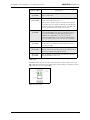
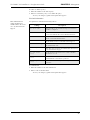
System LEDs Indication
Power
(green LED)
When lit, the switch is plugged in and the internal power
supply is functional.
Switch Fault
(yellow LED)
Indicates that the internal hardware self-test failed. When
lit, the switch will not function. -or-
Indicates that a fan has stopped operating or the ambient
temperature has exceeded 45°C. When lit, the switch is still
functional but requires immediate attention. The LED will
turn off when the detected condition is corrected.
Switch Op
(green LED)
Indicates whether the zones are initialized and operational.
If the Switch Op LED is lit, all zones with inserted devices
are operational. If the Switch Op LED is blinking in a
multiple zone configuration, one or more zones are
operational while others are not. If the Switch Op LED is
off, no operational zones exist or no devices are attached.
2 Gb/s
(green LED)
Indicates the current operational speed of the switch. When
lit, the switch is operating at 2 Gb/s. If unlit, the switch is
operating at 1 Gb/s.
Mgmt Present
(yellow LED)
Indicates that switch management is functioning. If
flashing, indicates that management functionality has failed
and is not communicating with the switch.
Enet Active
(green LED)
Indicates Ethernet activity on the switch and is controlled
through the Ethernet transceiver.

Vixel Model 335 Installation & Configuration Guide CHAPTER 2 Installation
8
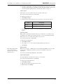
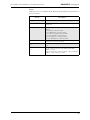
An explanation of the Port LED indicators is listed below:
SFP
Status
LED
Port
Bypassed/
Activity
LED
Indication
Off Off Normal status of operation for ports in which SFPs
are not installed.
The port will be in the bypass state, which precludes
the port from participating in the network.
On Off Normal operation. Port and device are operational.
On On
(Yellow)
Bypass. The port is non-operational due to loss of
signal, poor signal integrity, or the attached node is
sending LIP(F8,xx).
This is the normal status condition when the SFP is
present but not attached to a FC-AL node, or if it is
only attached to a cable assembly with nothing
attached at the opposite end. Replacing such a port
(or replugging the same port twice) is considered to
be a configuration change, which should initiate the
Loop Initialization Procedure by the attached device.
Off On
(Yellow)
Tx Fault. The port is non-operational due to an SFP
transmitter fault or improperly-seated SFP.
Off Blinking
(Yellow)
The port is being manually controlled by a
management entity.
Blinking Blinking
(Yellow)
A management entity is forcing a port beacon to
locate a particular port on the switch.
On On
(Green)
A connection has been made with the port.
Note: This LED is only applicable when the port is
operating in switching mode. If the port is in
switching mode and the LED is off, the port is not
currently involved in a transaction.

Vixel Model 335 Installation & Configuration Guide CHAPTER 2 Installation
9
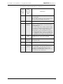
Cascading Switches
Cascading allows you to connect two or more switches together to increase the number
of ports and available devices. The switch allows you to link up to 12 switches. Multiple
cascades between switches provide link and communication redundancy. You may have
up to three cascades between a pair of switches.
Note: The primary switch
disables the transceivers on
all redundant connections,
so only the primary cascade
is enabled. If the primary
cascade goes down, another
cascade is then enabled.
The primary cascade is determined by the order of discovery in the primary switch (the
switch with the lower Serial Number). If the primary cascade fails in either switch, an
automatic failover occurs on one of the other cascades.
Figure 2-4. Cascading Switches in Overlapping Zones
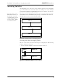
Cascading with Non-Overlapping Zones
There are certain cascade restrictions when using non-overlapping zones. The following
examples outline these restrictions.
1. You may only have multiple cascades between switches in Zone 1.
Figure 2-5. ACCEPTABLE: Multiple Cascades in Zone 1
Zone 1
Zone 1
Zone 1
Zone 1
Zones 2-12
Zone 1
Zones 2-12

Vixel Model 335 Installation & Configuration Guide CHAPTER 2 Installation
10
2. You may not have multiple cascades in Zones 2-12.
Figure 2-6. NOT ACCEPTABLE: Multiple cascades in Zones 2-12
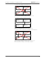
3. You may have a single cascade in Zones 2-12 only.
Figure 2-7. ACCEPTABLE: Single Cascade in Zones 2-12 Only
4. You may not create a cascade in Zone 1 and another cascade in Zones 2-12.
Figure 2-8. NOT ACCEPTABLE: Cascades in Zone 1 and Zones 2-12
For more information on zoning, see “Zone Settings” on page 31.
Zone 1
Zones 2-12
Zone 1
Zones 2-12
Zone 1
Zones 2-12
Zone 1
Zones 2-12
Zone 1
Zones 2-12
Zone 1
Zones 2-12

11
CHAPTER 3 Management
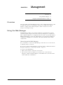
Overview
The switch utilizes both a Web Manager interface and a Command Line Interface (CLI)
to manage the switch. You can change the switch’s device identification, upgrade
firmware, configure switch settings and policies, define severity levels for event
messages, and configure zoning.
Using the Web Manager
The Web Manager enables you to manage and monitor a switch from any network-
connected computer. (Supported browsers are Netscape Navigator 4.7 or higher and
Microsoft Internet Explorer 5.0 or higher. The browser needs to be Javascript-enabled.)
With the Web Manager, you have the added benefits of easy navigation, simultaneous
configuration of multiple ports, and named—rather than enumerated values within
complex tables.
Connecting to the Web Manager
For a workstation to connect to the Web Manager, it must have access to the network
on which the switch is connected.
If you need to verify the switch’s IP address, log into the switch’s command line interface
through a serial link (see “Connecting to the CLI” on page 36).
To connect to the Web Manager:
1. Make sure the switch is connected to your network.
2. On a network-connected computer, open a web browser (such as Netscape
Navigator or Microsoft Internet Explorer); in the URL text box, enter the switch’s
address (DNS name or IP Address).
Overview 11
Using the Web Manager 11
Using the Command Line Interface (CLI) 36

Vixel Model 335 Installation & Configuration Guide CHAPTER 3 Management
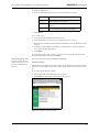
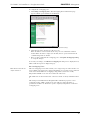
12
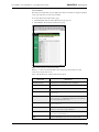
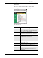
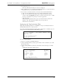
Figure 3-1. Web Manager Home Page
The Web Manager for the selected switch appears, and monitoring is available.
Configuration links and elements are visible only when you are logged in, as noted in
“Using the Command Line Interface (CLI)” on page 36.
Note: The web browser’s
appearance and
information depends on the
switch’s active firmware
version and may change
without notice in
subsequent firmware
versions.
To display updated information while using the Web Manager, click the Refresh button
on the page.
Navigation
To ensure that refreshed information is displayed, use the navigation links and buttons
(such as “Back”) that are on the Web Manager web pages. (The browser’s “Back” and
“Next” buttons usually display cached copies, which do not reflect the current
information on the switch.)
The highlighted button at the top of the page indicates your current location.
Logging On and Off
Note: For security, pass-
words (for accessing the
Web Manager & CLI) can
only be changed through a
serial connection to the
switch.
The Web Manager does not require log-on unless you want to modify the switch’s
parameters or configuration (such as zone or policy configurations).
To log on to the Web Manager, click Log In, type the correct password (the default is
password), and click Log On.
To log out of the Web Manager, click Log Out or close the browser window.
Note: One password is used to access both the Web Manager and the Command Line
Interface. You can change the password through the Command Line Interface (CLI)
only. Make sure you change the password after you log on the first time (for
instructions, see “Changing the CLI/Web Password” on page 43).

Vixel Model 335 Installation & Configuration Guide CHAPTER 3 Management
13
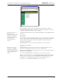
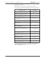
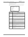
Configuring the Switch
A quick list of frequent configuration tasks and their locations is shown here. More
detailed information on each configuration task follows the table. Once you reach the
location, you may need to click Change Settings and/or other links or buttons before
configuration parameters are available for changing.
Note: To configure switch
settings, you must be
logged into the Web
Manager.
General switch status is shown on the Home page (click Home). You can click the
options at the top of the page to view additional information and configure the switch.
These options are discussed in more detail on the following pages.
Resetting the Switch
Changes to certain switch settings require you to reset the switch for those changes to
occur. You must be logged into the Web Manager to reset the switch.
To reset the switch, click Reset Switch on the Home page.
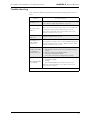
Configuration Task Location in Web Manager
Change the switch speed
(See “Switch Speed” on page 16.)
System > Change Settings
Change device identification, contact, and
location
(See “Switch Identification” on page 16.)
System > Change Settings
Upgrade firmware
(See “Firmware Settings” on page 18.)
System > Firmware
(click Load New Firmware Image)
Change the network settings (IP Address,
Gateway, and Netmask)
(See “Network Settings” on page 15.)
System > Change Settings
Change the time settings
(See “Time Settings” on page 17.)
System > Time > Change Time Settings
Configure zoning
(See “Zone Settings” on page 31.)
Zoning
View & download event log
(See “Event Log Messages” on page 19.)
System > Event Log
Reset switch
(See “Resetting the Switch” on page 13.)
Home (click Reset Switch)
View & update policies
(See “Policy Settings” on page 29.)
Policy

Vixel Model 335 Installation & Configuration Guide CHAPTER 3 Management
14
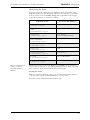
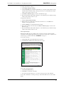
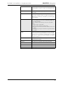
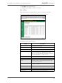
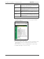
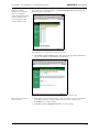
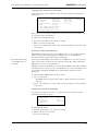
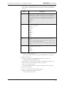
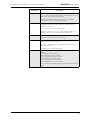
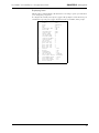
System Information Settings
The System Informations page displays the switch’s parameters and general
configuration settings.
To view the system settings, click System. The System Information page appears.
Figure 3-2. System Information Page
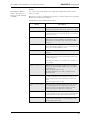
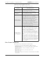
The displayed settings are listed below:
Setting Description
MAC Address A unique device address assigned to each switch at the
factory. Cannot be configured or modified.
Serial Num(ber) A unique identification number assigned to each switch at the
factory. Cannot be configured or modified.
IP Address The current IP Address for the switch.
IP Gateway The current Gateway address for the switch.
IP Netmask The current IP Netmask address for the switch.
Speed The current speed setting for the switch.
Speed Control (Last boot) The speed setting selected during the last switch power-up.
Speed Control (Next boot) The speed setting selected for the next switch power-up.
Switching Mode When "on", allows data to be sent directly to a specified port.
If "off", the data is sent to every port. Disabling Switching
Mode may be necessary when passing data to legacy devices.
Blocking ARB When two ports start a communication session, the Blocking
ARB is sent to all other ports trying to communicate with
those ports until the connection is terminated. Blocking ARB
is only active when the switching mode is on.

Vixel Model 335 Installation & Configuration Guide CHAPTER 3 Management
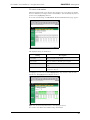
15
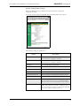
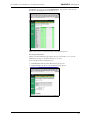
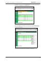
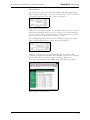
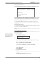
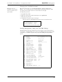
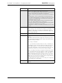
To modify the current settings, click Change Settings. The System Information page
appears with the fields available for modification.
Figure 3-3. System Information (Change Settings) Page
Network Settings
You can change the switch’s network settings (IP Address, Gateway, and Netmask)
through the Web Manager once the switch has established communications with the
network.
Note: To change the network settings of a switch that is not yet communicating with
your network, connect through a null modem serial cable and change the IP Address
through the CLI. For further information, See “Using the Command Line Interface
(CLI)” on page 36.
To view the current network settings, click System.
To change the switch’s network settings:
1. Click Change Settings.
2. Type the new setting (IP Address, Gateway, or Netmask) in the appropriate text box.
3. When finished, click Submit.
Agent Up Time The duration of time the switch has been operational.
Name The name of the switch.
Location The location where the switch resides.
Contact Name The person’s name to contact for switch issues.
HW Version The hardware version of the switch. Cannot be configured or
modified.
Setting Description

Vixel Model 335 Installation & Configuration Guide CHAPTER 3 Management
16
4. You must reset the switch for the new network settings to become active. To reset the
switch in the Web Manager, click Home and then click Reset Switch. You may also
reset the switch through the CLI. See “Resetting the Switch” on page 51.
Switch Speed
The switch is set to 2.125 Gb/s as the factory default switch speed.
To view the current switch speed, click System.
To change the switch speed:
1. Click Change Settings.
2. From the Speed Control (Next boot) drop-down box, select the desired speed.
3. Click Submit. The next time you reset the switch the new switch speed will be
applied.
Switching Mode
When enabled, switching mode allows data to be sent directly to a specified port. If
switching mode is disabled, the switch sends data to every port. Disabling Switching
Mode may be necessary when passing data to legacy devices.
To view the current mode, click System.
To change the switching mode:
1. Click Change Settings.
2. Select either "on" or "off" from the Switching Mode drop-down box.
3. Click Submit.
Blocking ARB
Note: This setting should
not be modified unless
directed to do so by Vixel
Customer Service.
When two ports start a communication session, the Blocking ARB is sent to any other
ports trying to communicate with those specific ports until their connection is
terminated.
To view the current Blocking ARB value, click System.
Switch Identification
You may modify the switch’s name, location, or contact name.
To view the current information, click System.
To change the switch identification:
1. Click Change Settings.
2. Enter the new value in the appropriate text box.
3. When finished, click Submit.
Setting Description
One Gig Set switch speed to 1.0625 Gb/s.
Two Gig Set switch speed to 2.125 Gb/s.

Vixel Model 335 Installation & Configuration Guide CHAPTER 3 Management
17
Downloading the Switch Configuration
You can download the current switch configuration to the Web Manager. The
configuration file displays in text format.
To download the switch configuration, click Download Switch Configuration File. A
text file appears displaying the current switch configuration. You can save or print the
information.
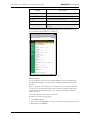
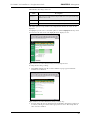
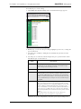
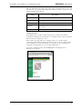
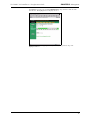
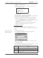
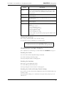
Time Settings
To view the current time settings, click System and then click Time. The Time
Information page appears.
Figure 3-4. Time Information Page
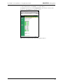
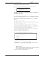
To change the time settings, click Change Time Settings. The Time Information page
appears with the fields available for modification.
Figure 3-5. Time Information (Change Settings) Page
Page is loading ...
Page is loading ...
Page is loading ...
Page is loading ...
Page is loading ...
Page is loading ...
Page is loading ...
Page is loading ...
Page is loading ...
Page is loading ...
Page is loading ...
Page is loading ...
Page is loading ...
Page is loading ...
Page is loading ...
Page is loading ...
Page is loading ...
Page is loading ...
Page is loading ...
Page is loading ...
Page is loading ...
Page is loading ...
Page is loading ...
Page is loading ...
Page is loading ...
Page is loading ...
Page is loading ...
Page is loading ...
Page is loading ...
Page is loading ...
Page is loading ...
Page is loading ...
Page is loading ...
Page is loading ...
Page is loading ...
Page is loading ...
Page is loading ...
Page is loading ...
Page is loading ...
Page is loading ...
Page is loading ...
Page is loading ...
Page is loading ...
Page is loading ...
Page is loading ...
Page is loading ...
Page is loading ...
Page is loading ...
Page is loading ...
Page is loading ...
Page is loading ...
Page is loading ...
Page is loading ...
Page is loading ...
-
 1
1
-
 2
2
-
 3
3
-
 4
4
-
 5
5
-
 6
6
-
 7
7
-
 8
8
-
 9
9
-
 10
10
-
 11
11
-
 12
12
-
 13
13
-
 14
14
-
 15
15
-
 16
16
-
 17
17
-
 18
18
-
 19
19
-
 20
20
-
 21
21
-
 22
22
-
 23
23
-
 24
24
-
 25
25
-
 26
26
-
 27
27
-
 28
28
-
 29
29
-
 30
30
-
 31
31
-
 32
32
-
 33
33
-
 34
34
-
 35
35
-
 36
36
-
 37
37
-
 38
38
-
 39
39
-
 40
40
-
 41
41
-
 42
42
-
 43
43
-
 44
44
-
 45
45
-
 46
46
-
 47
47
-
 48
48
-
 49
49
-
 50
50
-
 51
51
-
 52
52
-
 53
53
-
 54
54
-
 55
55
-
 56
56
-
 57
57
-
 58
58
-
 59
59
-
 60
60
-
 61
61
-
 62
62
-
 63
63
-
 64
64
-
 65
65
-
 66
66
-
 67
67
-
 68
68
-
 69
69
-
 70
70
-
 71
71
-
 72
72
-
 73
73
-
 74
74


Ask a question and I''ll find the answer in the document
Finding information in a document is now easier with AI
Related papers
Other documents
-
Emulex 355 User manual
-
-
-
-
-
HP P4459A User manual
-
Bull Storage Area Network (SAN) Installation guide
-
Dell PowerEdge M1000e Quick start guide
-
-
Avid Unity MediaNet 2.0 Installation guide