VOLTCRAFT 10 13 66 Operating Instructions Manual
- Category
- Coffee making accessories
- Type
- Operating Instructions Manual
This manual is also suitable for
Page is loading ...

VOLTCRAFT IM INTERNET http://www.voltcraft.de
Impressum
Diese Bedienungsanleitung ist eine Publikation von Voltcraft
®
, Lindenweg 15, D-92242 Hirschau, Tel.-Nr. 0180/586 582 7
(www.voltcraft.de).
Alle Rechte einschließlich Übersetzung vorbehalten. Reproduktionen jeder Art, z.B. Fotokopie, Mikroverfilmung, oder die Erfassung in
elektronischen Datenverarbeitungsanlagen, bedürfen der schriftlichen Genehmigung des Herausgebers. Nachdruck, auch auszugswei-
se, verboten.
Diese Bedienungsanleitung entspricht dem technischen Stand bei Drucklegung. Änderung in Technik und Ausstattung vorbehalten.
© Copyright 2008 by Voltcraft
®
Impressum /legal notice in our operating instructions
These operating instructions are a publication by Voltcraft
®
, Lindenweg 15, D-92242 Hirschau/Germany, Phone +49 180/586 582 7
(www.voltcraft.de).
All rights including translation reserved. Reproduction by any method, e.g. photocopy, microfilming, or the capture in electronic data
processing systems require the prior written approval by the editor. Reprinting, also in part, is prohibited.
These operating instructions represent the technical status at the time of printing. Changes in technology and equipment reserved.
© Copyright 2008 by Voltcraft
®
Informations /légales dans nos modes d'emploi
Ce mode d'emploi est une publication de la société Voltcraft
®
, Lindenweg 15, D-92242 Hirschau/Allemagne, Tél. +49 180/586 582 7
(www.voltcraft.de).
Tous droits réservés, y compris de traduction. Toute reproduction, quelle qu'elle soit (p. ex. photocopie, microfilm, saisie dans des
installations de traitement de données) nécessite une autorisation écrite de l'éditeur. Il est interdit de le réimprimer, même par extraits.
Ce mode d'emploi correspond au niveau technique du moment de la mise sous presse. Sous réserve de modifications techniques et de
l'équipement.
© Copyright 2008 by Voltcraft
®
Colofon in onze gebruiksaanwijzingen
Deze gebruiksaanwijzing is een publicatie van de firma Voltcraft
®
, Lindenweg 15, D-92242 Hirschau/Duitsland, Tel. +49 180/586 582 7
(www.voltcraft.de).
Alle rechten, vertaling inbegrepen, voorbehouden. Reproducties van welke aard dan ook, bijvoorbeeld fotokopie, microverfilming of de
registratie in elektronische gegevensverwerkingsapparatuur, vereisen de schriftelijke toestemming van de uitgever. Nadruk, ook van
uittreksels, verboden.
Deze gebruiksaanwijzing voldoet aan de technische stand bij het in druk bezorgen. Wijziging van techniek en uitrusting voorbehouden.
© Copyright 2008 by Voltcraft
®
01_1108_01/HK

2
Diese Bedienungsanleitung gehört zu diesem Produkt. Sie enthält wichtige Hinweise zur
Inbetriebnahme und Handhabung. Achten Sie hierauf, auch wenn Sie dieses Produkt an Dritte
weitergeben.
Heben Sie deshalb diese Bedienungsanleitung zum Nachlesen auf!
Eine Auflistung der Inhalte finden Sie in dem Inhaltsverzeichnis mit Angabe der entsprechenden
Seitenzahlen auf Seite 4.
These operating instructions belong with this product. They contain important information for
putting it into service and operating it. This should be noted also when this product is passed on
to a third party.
Therefore look after these operating instructions for future reference!
A list of contents with the corresponding page numbers can be found in the index on page 13.
Ce mode d'emploi appartient à ce produit. Il contient des recommandations en ce qui concerne
sa mise en service et sa manutention. Veuillez en tenir compte et ceci également lorsque vous
remettez le produit à des tiers.
Conservez ce mode d'emploi afin de pouvoir vous documenter en temps utile.!
Vous trouverez le récapitulatif des indications du contenu à la table des matières avec mention
de la page correspondante à la page 22.
Deze gebruiksaanwijzing hoort bij dit product. Er staan belangrijke aanwijzingen in betreffende
de ingebruikname en gebruik, ook als u dit product doorgeeft aan derden.
Bewaar deze handleiding zorgvuldig, zodat u deze later nog eens kunt nalezen!
U vindt een opsomming van de inhoud in de inhoudsopgave met aanduiding van de pagina-
nummers op pagina 31.
Page is loading ...
Page is loading ...
Page is loading ...
Page is loading ...
Page is loading ...
Page is loading ...
Page is loading ...
Page is loading ...
Page is loading ...
Page is loading ...

13
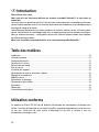
Introduction
Dear Customer,
Thank you for making the excellent decision to purchase this Voltcraft® product.
You have acquired a high-quality product with a brandname that stands out for professional competence
and permanent innovation in the field of measuring, charging and power technology.
With Voltcraft®, you will be able to cope even with difficult tasks as an ambitious hobbyist or as a pro-
fessional user. Voltcraft® offers reliable technology with an exceptional cost-performance ratio.
We are positive: Starting to work with Voltcraft will also be the beginning of a long, successful relation-
ship.
Enjoy your new Voltcraft® product!
Table of contents
Introduction ............................................................................................................................................13
Intended use ..........................................................................................................................................13
Safety instructions ..................................................................................................................................14
Scope of delivery ....................................................................................................................................16
Controls ..................................................................................................................................................16
Operation................................................................................................................................................17
Positioning the device ............................................................................................................................17
Connecting an switching on the device ..................................................................................................17
Setting the temperature ..........................................................................................................................17
Measuring ..............................................................................................................................................18
Maintenance and cleaning......................................................................................................................19
Changing the fuse ..................................................................................................................................19
Disposal..................................................................................................................................................19
Troubleshooting ......................................................................................................................................20
Specifications..........................................................................................................................................21
Intended use
The IRS-350 Blackbody is a calibration device for non-contact infrared thermometers. The calibration
area is an electronically controlled heating element with a matt black surface. The emission ratio of the
calibration area is 0.95. It is suitable for all common IR thermometers.

14
The temperature in °Celsius is set by membrane buttons and can be controlled through displays of actu-
al temperature and setpoint temperature. The integrated fan allows quick temperature changes of the
calibration area. The setting range is from +50 to +350 °C.
In addition, the device is equipped with an opening at the housing top to calibrate or test contact ther-
mometers with immersion sensors or penetration probes (max. diameter of shaft 3 mm).
The design of this product complies with safety class I. It is only approved for connection to shockproof
sockets with protective grounding and an alternating current of 230 V/AC 50 Hz commonly used in
households.
Operation under adverse environmental conditions is not permitted. Adverse ambient conditions include:
- moistness or high humidity
- dust and combustible gases, vapours or solvents
- storms or stormy conditions, strong electrostatic fields, etc.
Any use other than that described above will damage the product and may involve other risks, such as
short-circuit, fire, electric shock. Do not change or modify any part of the product!
No part of the product must be modified or rebuilt!
The safety instructions must be observed!
Safety instructions
Please read through the operating instructions before using the product for the first
time; they contain important information on proper operation.
The warranty/guarantee is rendered void in cases of damage resulting from failure to
comply with these operating instructions! We assume no liability for any conse-
quential damage!
We do not assume liability for personal injury or material damage resulting from improper use or disre-
garding the safety instructions! In such cases the warranty/guarantee is voided.
This device left the factory in perfect condition in terms of safety engineering.
To maintain this condition and ensure safe operation, you, as the user, must comply with the safety
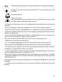
instructions and warnings contained in these instructions. The following symbols must be observed:
An exclamation mark in a triangle indicates important information in these operating
instructions that has to be observed.
This product has been CE-tested and meets the necessary European guidelines.
°

15
☞
The hand symbol indicates special information and advice on the operation of the device.
Terminal for the internal protective earth conductor; this screw/contact must not be
unscrewed.
Only for dry indoor use
Caution, hot surface!
There is a risk of burns when touched. Never touch heating or cooling areas during opera-
tion. Allow the device to cool down before touching it.
For safety and licensing reasons (CE), unauthorised conversion and/or modification of the device is not
permitted.
Consult an expert when in doubt about the operation, the safety or the connection of the device.
The device must not be opened. Live components may be exposed if covers are opened or components
are removed. Capacitors inside the device may still be charged, even if the device has been disconnect-
ed from all voltage sources.
Comply with the safety and operating instructions of any other appliances that are connected to the
device as well as to the individual chapters in these instructions.
Never touch the device with wet or moist hands. There is a risk of a fatal electric shock.
The device may never be operated unsupervised.
Only use fuses of the rated type and current. It is not permissible to repair fuses of bridge them.
Measuring instruments and accessories are no toys and do not belong in the hands of children!
The accident prevention regulations of the relevant trade associations for electrical systems and operat-
ing materials are to be observed in commercial institutions.
In schools, training centres, computer and self-help workshops, handling of measuring instruments must
be supervised by trained personnel in a responsible manner.
Never switch on the device immediately after taking it from a cold to a warm environment. The conden-
sation generated could cause serious damage to the device. Allow the device to reach room temperature
before switching it on.
Do not leave packaging material lying around carelessly. It could become a dangerous toy in the hands
of children.
The device heats up during operation. make sure sufficient ventilation is provided; do not cover the
housing!

16
If you have reason to believe that the device can no longer be operated safely, disconnect it immediate-
ly and make sure it is not unintentionally operated. It can be assumed that safe operation is no longer
possible if:
• the device shows visible damage,
• the device does not function any longer or
• after it has been stored under unfavourable conditions over a period of time or
• after it has been exposed to heavy stress during transport.
You should also observe the safety instructions in the individual chapters of these operating instructions
and in the operating instructions of the devices to be calibrated.
Scope of delivery
IRS-350 Blackbody
Mains cable
Operating instructions
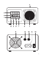
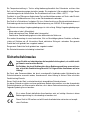
Controls
(See illustration on the fold-out page)
1 Function displays
AT Display for factory adjustment only
OUT Heating indicator
ALM1 Excess temperature (heating element off)
ALM2 Excess temperature (increased cooling activated)
°C Display of temperature unit for Europe in degrees Celsius (°F not active)
2 Green display of setpoint temperature
3 Red display of actual temperature
4 Contact sensor opening for measuring (max. ø 3 mm)
5 Calibration area (heating element)
6 Cooling area
7 UP button to increase settings
8 DOWN button to decrease settings
9 Button for factory adjustment only (inactive)
10 SET button for input acknowledgement
11 Fan opening
12 Fuse holder for heating element fuse
13 Fuse holder for mains fuse
14 Mains connection
15 On-off switch

17
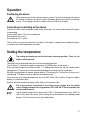
Operation
Positioning the device
Place the device on the flat and heat-resistant surface. The surface might get warm due to
the air flow coming from the device. Keep inflammable objects away from the calibration
area (5). Ensure proper ventilation. Keep a minimum of 20 cm on all sides.
Connecting an switching on the device
Connect the mains cable to the power supply socket at the back (14) and to a mains socket with protec-
tive grounding.
Use the on-off switch (15) to turn on the device.
Switch position ON = on (I)
Switch position OFF = off (0)
The fan starts running and a system test is carried out. After about 3 seconds, the last setpoint tempera-
ture and the last actual temperature are shown.
Setting the temperature
The cooling and heating area on the front heats up during operation. There is a risk
of burns when touched!
Two buttons on the blackbody allow you to set the desired temperature.
The UP button (7) increases to setpoint temperature, the DOWN button (8) decreases it.
Every keystroke changes the temperature by 0.1 °C. Holding down one of the two keys speeds up the
setting process. There are three setting speeds depending on how long a button is held down.
During the setting process the green setpoint display (2) flashes quickly. This confirms that you are in
setting mode. This does not have an effect on the temperature yet.
Once you have set the desired temperature, press the SET button (10) to confirm. The green setpoint
display (2) is permanent again.
Now the red actual temperature display slowly adjusts to the setpoint value.
Due to the system’s characteristics, the setting range is bigger than the control
range. Settings outside of the range between 50°C and 350°C are not specified and
can overload the device.
☞
It takes the device about 30 minutes to reach +350°C. The cooling process from +350°C to
100°C takes about 40 minutes. After reaching the set temperature, the blackbody needs
between 15 to 20 minutes to reach the stated stability.

18
If the temperature is increased, the heating process is indicated by function display OUT (1).
If the temperature is decreased, function display OUT goes out or starts flashing. If the actual tempera-
ture (display 3) is above the setpoint temperature by more than 4°C (display 2), both red function dis-
plays ALM1 and ALM2 are activated. The displays indicate a significant difference in temperature. If the
difference is less than 4°C, the displays go out.
ALM1: the heating process stops temporarily
ALM2: the cooling process is intensified.
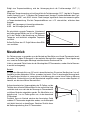
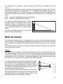
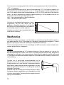
There is only little difference between the actual and
the setpoint temperature of the physically generated
temperature (heating element). The graph shows the
difference between reference temperature and actual
temperature.
External factors like draught can increase this differ-
ence.
Measuring
To avoid faulty measurements, the distance between the measuring area and the infrared thermometer
must be taken into account. The optical measuring ratio is stated for every IR measuring instrument. This
ratio states at what distance the measuring cone has a certain diameter.
If the measured area is smaller then the measuring cone of the IR thermometer, false values will be dis-
played.
Example:
An optical measuring ratio of 10:1 measures an area of 1 cm at a distance of 10 cm. If the distance is
increased to 100 cm, an area of 10 cm is needed to measure correctly. The bigger the ratio the more pre-
cise the results, because only a small area is needed to carry out the measurement. The measuring dis-
tance can be increased which will render the same results as a small measuring ratio.
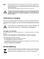
Due to mechanical inaccuracies of IR optics and due to the fact
that infrared heat rays are invisible to the human eye, a tolerance
range has to be kept to the colder areas when measuring. There-
fore, the radius of the measuring area must be at least 1 cm bigger
than the radius of the calculated IR measuring cone.
In addition, a distance has to be kept between the thermal source
and the IR thermometer to avoid any direct thermal influence on
the measuring optics. Please also observe the operating instruc-
tions of your IR thermometer.

19
☞
At the housing top, there is an opening (4) for penetration probes with a shaft diameter of
max. 3 mm. This opening is used to calibrate normal thermometers and to control the tem-
perature of the calibration area with a contact thermometer.
Insert the probe at right angle into the opening until the probe has made contact.
After measuring, the temperature has to be set to less than 60°C. Do not turn of the
device while the display shows more than 60°C. The accumulated heat might destroy
the device. Never leave the device unattended when it cools down.
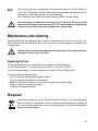
Maintenance and cleaning
Apart from cleaning or exchanging the fuse, the device is maintenance-free. Use a clean, lint-free, anti-
static and dry cloth to clean the device. Do not use any abrasive or chemical agents or detergents con-
taining solvents.
Allow the device to cool down completely before cleaning it. Touching the heating or
cooling area involves the risk of burns.
Replacing the Fuse
The heating element and the control electronics in the device are fused separately.
Fuse for heating element (12), quick-acting fine-wire fuse 6.3 x 30 mm F1.5 A/250 V
Fuse for control electronics (13), quick-acting fine-wire fuse 6.3 x 30 mm F500 mA/250 V
Proceed as follows to replace the fuse:
- Turn off the device and disconnect the power supply.
- Turn the respective fuse holder out of the housing.
- Replace the defective fuse with a new fuse of the same type and nominal voltage.
- Carefully screw the fuse holder shut again.
- The device can be operated again.
Disposal
Used electronic products are raw materials and do not belong in the household waste.
When the device has reached the end of its service life, please dispose of it according to
the current statutory requirements at your local collecting point. It is prohibited to dispose of
batteries in household waste.

20
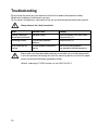
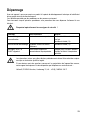
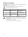
Troubleshooting
By purchasing this device you have acquired a state-of-the-art product which operates reliably.
Nevertheless, problems or malfunctions may occur.
For this reason, the following is a description of how you can eliminate possible malfunctions yourself:
Always observe the safety instructions!
Error Possible cause Remedy
Nothing is displayed, No power supply Check the position of the mains cable.
device does not function Check the fuse (13)
No heating function Fuse of heating element Check the fuse (12)
defective
ALM1 and ALM2 are Current temperature difference Wait until the heating element
flashing too big has reached the desired temperature.
Repairs other than those described should only be carried out by an authorised specialist.
If you have questions concerning the use of the measuring device, our technical support
service is available at the following telephone number:
Voltcraft, Lindenweg 15, 92242 Hirschau, tel. no. 0180 / 586 582 7

21
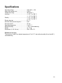
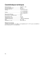
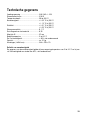
Specifications
Operating voltage ............................................230 V/AC +/- 10%
Power consumption max. ................................210 W
Temperature range ..........................................50 to 350 °C
Accuracy..........................................................+/- 0.5 °C at 100 °C
+/- 1.2 °C at 350 °C
Stability............................................................+/- 0.1 °C at 100 °C
+/- 0.2 °C at 350 °C
Display step size..............................................0.1 °C
Emission ratio of measuring area ....................0,95
Emission area Ø ..............................................57 mm
Operating temperature ....................................5 to 35 °C
Relative humidity ............................................< 80 %, non-condensing
Weight..............................................................ca. 2.1 kg
Dimensions (L x W x H mm) ............................248 x 190 x 113
Definition of accuracy
The accuracy is valid at an ambient temperature of 5 to 35 °C and relative humidity of less than 80 %,
non-condensing.
Page is loading ...
Page is loading ...
Page is loading ...
Page is loading ...
Page is loading ...
Page is loading ...
Page is loading ...
Page is loading ...
Page is loading ...
Page is loading ...
Page is loading ...
Page is loading ...
Page is loading ...
Page is loading ...
Page is loading ...
Page is loading ...
Page is loading ...
Page is loading ...
Page is loading ...
Page is loading ...
-
 1
1
-
 2
2
-
 3
3
-
 4
4
-
 5
5
-
 6
6
-
 7
7
-
 8
8
-
 9
9
-
 10
10
-
 11
11
-
 12
12
-
 13
13
-
 14
14
-
 15
15
-
 16
16
-
 17
17
-
 18
18
-
 19
19
-
 20
20
-
 21
21
-
 22
22
-
 23
23
-
 24
24
-
 25
25
-
 26
26
-
 27
27
-
 28
28
-
 29
29
-
 30
30
-
 31
31
-
 32
32
-
 33
33
-
 34
34
-
 35
35
-
 36
36
-
 37
37
-
 38
38
-
 39
39
-
 40
40
-
 41
41
-
 42
42


VOLTCRAFT 10 13 66 Operating Instructions Manual
- Category
- Coffee making accessories
- Type
- Operating Instructions Manual
- This manual is also suitable for
Ask a question and I''ll find the answer in the document
Finding information in a document is now easier with AI
in other languages
- français: VOLTCRAFT 10 13 66
- Deutsch: VOLTCRAFT 10 13 66
- Nederlands: VOLTCRAFT 10 13 66
Related papers
-
VOLTCRAFT DO-10 Operating instructions
-
-
-
-
-
-
-
-
-
Other documents
-
Dostmann BB 500 Temperatur-Kalibrator User manual
-
Ebro EBTLC730 Owner's manual
-
Enraf-Nonius Halogen IR Radiator IRS User manual
-
-
Trotec IRS 2000 E Operating instructions
-
 Spacio Innovations WS-4WUS User manual
-
 Isotech Blackbody Source Model 989 User guide
-
Laserliner ThermoXplorer Pro User manual
-
 Sybility IR-EASY User manual


