Page is loading ...

http://www.omega.com
e-mail: [email protected]
®
User’s Guide
CN9300/CN9500
Autotune Temperature Controllers
omega.com
TM
OMEGA
®
OMEGAnet
SM
On-Line Service Internet e-mail
http://www.omega.com [email protected]
It is the policy of OMEGA to comply with all worldwide safety and EMC/EMI regulations that apply. OMEGA is constantly pursuing certification of its products to the European New
Approach Directives. OMEGA will add the CE mark to every appropriate device upon certification.
The information contained in this document is believed to be correct but OMEGA Engineering, Inc. accepts no liability for any errors it contains, and reserves the right to alter
specifications without notice.
WARNING: These products are not designed for use in, and should not be used for, patient connected applications.
Benelux:
Postbus 8034, 1180 LAAmstelveen,
The Netherlands
Tel: (31) 20 6418405 FAX: (31) 20 6434643
Toll Free in Benelux: 06 0993344
e-mail: [email protected]
Czech Republic:
ul. Rude armady 1868, 733 01 Karvina-Hranice,
Czech Republic
Tel: 420 (69) 6311899 FAX: 420 (69) 6311114
e-mail: [email protected]
France:
9, rue Denis Papin, 78190 Trappes
Tel: (33) 130-621-400 FAX: (33) 130-699-120
Toll Free in France: 0800-4-06342
e-mail: [email protected]
Servicing Europe:
USA and Canada:
Sales Service: 1-800-826-6342 / 1-800-TC-OMEGA
SM
Customer Service: 1-800-622-2378 / 1-800-622-BEST
SM
Engineering Service: 1-800-872-9436 /
1-800-USA-WHEN
SM
TELEX: 996404 EASYLINK: 62968934
CABLE: OMEGA
USA: ISO 9001 Cer
tified
One Omega Drive, Box 4047
Stamford, CT 06907-0047
Tel: (203) 359-1660
FAX: (203) 359-7700
e-mail: [email protected]
Servicing North America:
For immediate technical or application assistance:
Mexico and Latin America:
Tel: (95) 800-TC-OMEGA
SM
FAX: (95) 203-359-7807
En Espan
~
ol: (203) 359-7803
e-mail: [email protected]
Germany/Austria:
Daimlerstrasse 26, D-75392
Deckenpfronn, Germany
Tel: 49 (07056) 3017 FAX: 49 (07056) 8540
Toll Free in Germany: 0130 11 21 66
e-mail: [email protected]
United Kingdom: ISO 9002 Cer
tified
•25 Swannington Road, Broughton Astley,
Leicestershire, LE9 6TU, England
Tel: 44 (1455) 285520
FAX: 44 (1455) 283912
•P.O. Box 7, Omega Drive, Irlam,
Manchester, M44 5EX, England
Tel: 44 (161) 777-6611
FAX: 44 (161) 777-6622
Toll Free in England: 0800-488-488
e-mail: [email protected]
Canada:
976 Bergar
Laval (Quebec) H7L 5A1
Tel: (514) 856-6928
FAX: (514) 856-6886
e-mail: [email protected]
M2897/0498

Safety and Warranty
SAFETY AND WARRANTY INFORMATION
INSTALLATION
Designed for use:
UL873 - only in products where the acceptability is
determined by Underwriters Laboratories Inc.
EN61010-1 / CSA 22.2 No 1010.1 - 92
To offer a minimum of Basic Insulation only.
Suitable for installation within Catagory II and III and Pollution
Degree 2.
SEE ELECTRICAL INSTALLATION P29 & P30
It is the responsibility of the installation engineer to ensure
this equipment is installed as specified in this manual and is
in compliance with appropriate wiring regulations.
CONFIGURATION
All functions are front selectable, it is the responsibility of
the installing engineer to ensure that the configuration is
safe. Use the program lock to protect critical functions from
tampering.
ULTIMATE SAFETY ALARMS
Do not use SP2 as the sole alarm where personal injury or
damage may be caused by equipment failure.
INDEX
SAFETY A1
FUNCTIONS MENU A3
QUICK START
Quick Start Set-up 1a
INTRODUCTION 2
The controllers 2
OVERVIEW 3
Installation 3
Set-up 3
Autotune 3
Cycle-time 4
SET-UP 5
Power-up 5
Select input sensor 5
Select display units 5
Allocate output device 5
Enter initial configuration 5
Set main setpoint 5
MENU NAVIGATION 6
Using program mode 6
AUTOTUNE 7
Tune program 7
Tune at setpoint program 8
PROPORTIONAL CYCLE-TIME 9
Cycle-time selection methods 9
Cycle-time recommendations 9
Autotune calculated cycle-time 9
PROGRAMMER 11
Ramp-Soak 11
SECOND SETPOINT (SP2) 12
SP2 as an alarm 12
SP2 subsidiary mode 13
SP2 as a proportional output 13
SP2 alarm condition table 13
SP2 alarm annunciator 13
ERROR MESSAGES 14
Recommendations 14
Autotune data in
tECH
14
IMPROVING CONTROL ACCURACY 15
Using
ChEK
accuracy monitor 15
FUNCTION LIST 16
Level 1 16
Level 2 18
Level 3 19
Level 4 21
OUTPUT OPTIONS 22
ADVANCED SETTINGS 23
Heat Cool strategy 23
Calibration to other instrument 24
Linear input calibration 25
MECHANICAL INSTALLATION 27
DIN panel cut-outs 27
Minimum spacing 27
Mounting 28
ELECTRICAL INSTALLATION 29
General requirements 29
Connection diagrams 30
INPUT/SENSOR SELECTION 31
SPECIFICATION 32
WARRANTY INFORMATION Inside back cover
Index
A2A1

FUNCTIONS MENU
Functions Menu
INSTRUMENT ADJUSTMENTS
To enter or exit program mode: Press ▲ ▼ together for 3 seconds
To scroll through functions: Press ▲ or ▼
To change levels or options: Press ✱ ▲ together or ✱ ▼ together
To view setpoint: Press ✱
To increase setpoint: Press ✱ ▲ together
To decrease setpoint: Press ✱ ▼ together
To reset an alarm or fault condition: Press ▲ ▼ together briefly
Notes: If in difficulty by becoming “lost” in program mode, press ▲ and ▼
together for 3 seconds to return to display mode, check the
INSTRUMENT ADJUSTMENTS above and try again.
When in program mode, after 60 seconds of key inactivity the
display will revert to either INPT
nonE
or, if the
initial configuration has been completed, the measured value.
Any settings already completed will be retained.
Main setpoint
(SP1)
Second setpoint
(SP2)
Process temperature (PV)
or setpoint (SP)
BAND INT.T DER.T DAC CYC.T OFST SP.LK SPRR SPRN SOAK SET.2 BND.2 CYC.2
LEVL 1
TUNE
Autotune or Park
oFF; on; tunE; ParK; At.Sp
SP1 Prop band (gain)/hyst
0.1 deg to 25% sensor f/s
(10°C/18°F)
Integral time (reset)
Off; 0.1 to 60 min (5 min)
Derivative time (rate)
Off; 1 to 200 sec (25 sec)
Derivative approach
0.5 to 5.0 x bAnd (1.5)
Cycle time or on/off
On.off; 0.1 to 81 sec
(20 sec)
Offset (manual reset)
0 to 50% x bAnd
(In.t = off)
Setpoint lock (SP1)
Off; on
Setpoint Ramp rate
0 to 9990 deg/hour
Ramp off/on
On; off; hold
Soak time
Off; 0 to 1440 min
Adjust SP2 setpoint
+/– sensor full scale or
full scale
SP2 prop band/Gain/Hyst
0.1 deg to 100% sensor
f/s (2°C/3.6°F)
SP2 Cycle on/off
On.off; 0.1 to 81 sec
SP1 SETTINGS
BAUD DATA DBUG
LEVL C
ADDR
Instrument address
0 to 255
Baud rate
1200: 2400: 4800:
9600: 19k2
Data format
18n1:18E1:18O1
Tx/Rx activity
Off; on
COMMS SETTINGS
PROGRAMMER SETTINGS SP2 SETTINGS
HAND PL.1 PL.2 SP2.A SP2.B DISP HI.SC LO.SC INPT UNIT
LEVL 2
SP1.P
Read SP1 output %
0 to 100% read only
SP1 manual output %
0 to 100% proportional
mode only
Limit SP1 output %
100 to 0%
Limit SP2 output %
100 to 0%
Main SP2 mode
nonE; dV.hi; dV.Lo; bAnd;
FS.hi; FS,Lo; Cool
Second SP2 mode
nonE; LtCH; hold; Lt.ho;
nLin
Display resolution
1 or 0.1 degree
Set scale maximum
0.0 Sensor max to
sensor full scale
Set scale minimum
0.0 Sensor min to sensor
full scale
Select input sensor
nonE
Select display units
nonE; oC; oF; bAr;
PSi; Ph; rh; SEt
MANUAL ADJUSTMENTS SP2 MODES RANGING CONFIGURE INPUT
SP2.D BURN REU.D REU.L SPAN ZERO CHEK READ TECH UER RSET
LEVL 3
SP1.D
SP1 output device
nonE; rlY; SSd
*
SP2 output device
nonE; SSd; rlY (read only)
*
Sensor burn-out
uP.SC; dn.SC; 1u.2d; 1d.2u
Reverse outputs
1r.2d; 1d.2d; 1r.2r; 1d.2r
Reverse O/P LEDs
1n.2n; 1i.2n; 1n.2i; 1i.2i
Span adjustment
0.0 to 25% sensor f/s
Zero Adjustment
0.0 to 25%
sensor full scale
Set Monitor
Off; on
Read Monitor
VAr; hi; lo deg
Read Tune Data
CtA; Ctb; Ct1; Ct2; Ct3;
Ct4; oS1; uS; oS2
Software version
Consult unit
RESET
nonE; ALL
CONFIGURE OUTPUT SAFETY SETTINGS CALIBRATION PERFORMANCE DATA
PROG NO.AL DIS.S DER.S
LEVL 4
LOCK
Security lock
nonE; LEV 3; LEV 2; ALL
Disable program auto-exit
Auto; StAY
Disable -AL- alarm display
Off; on
Display averaging
dir; 1 to 32 (6)
Derivative sensitivity
0.1 to 1.0 x dEr.t (0.5)
USER-PROTECTED SETTINGS
PROGRAM ENTRY
Level C only visable
when COMMS
Option fitted
➔
QUICK START ENTRY
➔
KEY ▼ ▲ TO VIEW FUNCTIONS
KEY ✱ ▼ OR ✱ ▲ TOGETHER TO CHANGE LEVELS OR OPTIONS
Range of Adjustment shown in red under description. If
applicable, factory settings shown in bold.
* Note: Dual Relay and Dual SSd Output Options Models
CN9311 / CN9511 and CN9322 / CN9522 have their
outputs pre-configured. (see page 22)
A3

QUICK START
After power-up the controller requires programming with
the following information:
Type of Sensor (See list of temperature sensors p.31)
Operating unit (See list of units p.18)
Allocation of Output Device to SP1/SP2 (Relay or SSd)
Temperature Setpoint eg. Degrees
When the above information has been programmed into the
controller it will be operational with the following factory
settings.
Proportional band/Gain 10ºC/18ºF
Integral time/Reset 5 mins
Derivative time/Rate 25 secs
Proportional cycle-time 20 secs
(Typical setting for relay output)
DAC Derivative approach control 1.5
(Average setting for minimum overshoot)
NB: Please note that in the manual, functions are reversed
out from a black background and options are shown in
bold italic;
eg. TUNE and
ParK
Quick Start
Note: In this manual the letter k is represented by the
character K
1a
Note: During the following procedure the display will revert
to alternating INPT and
nonE
after 60
seconds of key inactivity, but will retain any
settings already completed. Should this occur, or in
the event of becoming ‘lost’ in the program, please
start again from the alternating INPT and
nonE
display.
QUICK START SET-UP
On power-up the controller will display the self test
sequence followed by alternating INPT and
nonE
1 Select input sensor.
Press and hold ✱ and use the ▲ or ▼ buttons to
scroll through the sensor selection
list until the correct sensor is
displayed. Release the buttons.
The display now alternates selected
sensor type (eg. INPT and
Tc.S
)
Press ▲ once The display will now alternate UNIT
and
nonE
FOR WARRANTY RETURNS, please have the following information
available BEFORE contacting OMEGA:
1. P.O. number under which the product was PURCHASED,
2. Model and serial number of the product under warranty, and
3. Repair instructions and/or specific problems relative to the product.
FOR NON-WARRANTY REPAIRS,
consult OMEGA for current repair
charges. Have the following information available BEFORE contacting
OMEGA:
1. P.O. number to cover the COST of the repair,
2. Model and serial number of product, and
3. Repair instructions and/or specific problems relative to the product.
OMEGA’s policy is to make running changes, not model changes, whenever an improvement is possible. This affords our customers the latest in technology and
engineering.OMEGA is a registered trademark of OMEGA ENGINEERING, INC.
© Copyright 1996 OMEGA ENGINEERING, INC. All rights reserved. This document may not be copied, photocopied, reproduced, translated, or reduced to any electronic
medium or machine-readable form, in whole or in part, without prior written consent of OMEGA ENGINEERING, INC.
WARRANTY/ DISCLAIMER
OMEGA ENGINEERING, INC. warrants this unit to be free of defects in materials and workmanship for a period of 37 months from date of purchase.
OMEGA Warranty adds an additional one (1) month grace period to the normal three (3) years product warranty to cover handling and shipping time.
This ensures that OMEGA’s customers receive maximum coverage on each product.
If the unit should malfunction, it must be returned to the factory for evaluation. OMEGA’s Customer Service Department will issue an Authorized Return (AR) number
immediately upon phone or written request. Upon examination by OMEGA, if the unit is found to be defective it will be repaired or replaced at no charge. OMEGA’s
WARRANTY does not apply to defects resulting from any action of the purchaser, including but not limited to mishandling, improper interfacing, operation outside
of design limits, improper repair, or unauthorized modification. This WARRANTY is VOID if the unit shows evidence of having been tampered with or shows
evidence of being damaged as a result of excessive corrosion; or current, heat, moisture or vibration; improper specification; misapplication; misuse or other operating
conditions outside of OMEGA’s control. Components which wear are not warranted, including but not limited to contact points, fuses, and triacs.
OMEGA is pleased to offer suggestions on the use of its various products. However, OMEGA neither assumes responsibility for any
omissions or errors nor assumes liability for any damages that result from the use of its products in accordance with information
provided by OMEGA, either verbal or written. OMEGA warrants only that the parts manufactured by it will be as specified and free of
defects. OMEGA MAKES NO OTHER WARRANTIES OR REPRESENTATIONS OF ANY KIND WHATSOEVER, EXPRESSED OR IMPLIED,
EXCEPT THAT OF TITLE, AND ALL IMPLIED WARRANTIES INCLUDING ANY WARRANTY OF MERCHANTABILITY AND FITNESS FOR A
PARTICULAR PURPOSE ARE HEREBY DISCLAIMED. LIMITATION OF LIABILITY: The remedies of purchaser set forth herein are exclusive
and the total liability of OMEGA with respect to this order, whether based on contract, warranty, negligence, indemnification, strict
liability or otherwise, shall not exceed the purchase price of the component upon which liability is based. In no event shall OMEGA be
liable for consequential, incidental or special damages.
CONDITIONS: Equipment sold by OMEGA is not intended to be used, nor shall it be used: (1) as a “Basic Component” under 10 CFR 21 (NRC), used in or
with any nuclear installation or activity; or (2) in medical applications or used on humans. Should any Product(s) be used in or with any nuclear
installation or activity, medical application, used on humans, or misused in any way, OMEGA assumes no responsibility as set forth in our basic
WARRANTY/DISCLAIMER language, and additionally, purchaser will indemnify OMEGA and hold OMEGA harmless from any liability or damage
whatsoever arising out of the use of the Product(s) in such a manner.
RETURN REQUESTS/ INQUIRIES
Direct all warranty and repair requests/inquiries to the OMEGA Customer Service Department. BEFORE RETURNING ANY PRODUCT(S) TO OMEGA,
PURCHASER MUST OBTAIN AN AUTHORIZED RETURN (AR) NUMBER FROM OMEGA’S CUSTOMER SERVICE DEPARTMENT (IN ORDER TO AVOID
PROCESSING DELAYS). The assigned AR number should then be marked on the outside of the return package and on any correspondence.
The purchaser is responsible for shipping charges, freight, insurance and proper packaging to prevent breakage in transit.

2 Select unit.
Press and hold ✱and use the ▲ or ▼ buttons to
scroll through the unit selection list
until the correct unit is displayed.
Release the buttons.
The display will now alternate
selected unit (eg. UNIT and
°C
).
Press ▲ once The display will now alternate
SP1.D and
nonE
3 Select SP1 (Main setpoint output device)
Note: Dual Relay and Dual SSd Output Options Models
CN9311 / CN9511 and CN9322 / CN9522 have their
outputs pre-configured. (see page 22)
Press and hold ✱and use the ▲ or ▼ buttons to select
SSd
or
rLY
as required. The controller
will now alternate selected output device
(e.g. SP1.D and
SSd
).
Quick Start
QUICK START
1b
4 To enter initial configuration into controller
memory
Press and hold both ▲ and ▼ buttons for 3 seconds. The
display will now alternate
ParK
and
measured variable (temperature)
(eg.
23
)
ParK
is displayed
because a setpoint has not yet been
entered.
To display setpoint
Press and hold ✱ The display will now alternate
0
and
unit
(eg.
°C
)
To enter setpoint
Press and hold ✱and use ▲ button to increase or ▼ button
to decrease the reading and scroll to
required setpoint value. (The digit roll-over
rate increases with time).
THE CONTROLLER IS NOW OPERATIONAL
WITH FACTORY SETTINGS
Note: For precise control of an application the controller
may need to be TUNED. Please study section
headed FUNCTIONS and OPTIONS before moving to
the section on AUTOTUNE.

Introduction
INTRODUCTION
THE CONTROLLERS
The CN9500 1/32 DIN and the CN9300 1/16 DIN miniature
controllers share the same PID control strategy and features
while giving the user the flexibility of a choice of panel
format. Control can be optimised with a single shot autotune
either on initial warm-up or at setpoint. A second setpoint
can be configured in a variety of alarm modes or PID Heat-
Cool strategy. A programmer offers a single ramp to setpoint
with a choice of timed soak period before switching off the
output.
Control of non temperature processes is achieved by the
provision of linear input ranges and scaling in commonly
used engineering units.
Serial communication is available as an option on both
controllers, and the easy to use CN9-SW is a graphic
WINDOWS
TM
based software package designed for PC
supervision of up to 32 instruments, for remote adjustment,
configuration, cloning, saving and retrieving settings to files
and logging and charting in real time.
CN9-SW uses the MODBUS
®
protocol via either a fully
isolated RS232 or RS485 link depending on the number of
instruments and the transmission distances involved in the
application.
A users manual is supplied with the comms option. For more
information contact Omega. For details, see rear cover.
It is suggested that users read the OVERVIEW section of this
manual before any installation or setting-up procedures are
undertaken.
Note: The controller will not be operational until either the
QUICK-START or SET-UP procedure has been
completed.
NB: Please note that in the manual, functions are
reversed out from a black background and options are
shown in bold italic;
eg. TUNE and
ParK
2

Overview
OVERVIEW
INSTALLATION
The Model CN9500 controller is designed to be mounted in
a 1/32 DIN panel cutout and the Model CN9300 in a 1/16
DIN cutout. See the INSTALLATION section.
SET-UP
After installation the controller requires programming with
the following information:
Type of Input Sensor
Operating unit (C or F etc)
Type of Output Device
Temperature Setpoint
Note: The controller will not be operational until this
information is entered.
When the above information has been programmed into the
controller it will be operational with the following factory
PID (proportional band, integral time, derivative time)
settings.
Proportional band/Gain 10°C/18°F
Integral time/Reset 5 mins
Proportional cycle-time 20 secs
Derivative time/Rate 25 secs
DAC Derivative approach control 1.5
AUTOTUNE
To precisely control an application the controller will need
to be ‘tuned’ using the built-in ‘AUTOTUNE’ feature.
Autotune ‘teaches’ the controller the main characteristics of
the process and ‘learns’ by cycling the output on and off.
The results are measured and used to calculate optimum PID
values which are automatically entered in the controller
memory.
During AUTOTUNE the optimum cycle-time is calculated but
is not automatically implemented. The cycle-time requires
manual acceptance unless pre-selected.
To ensure good control over a wide range of applications
two versions of the Autotune program are provided, TUNE
and TUNE AT SETPOINT.
The TUNE method normally achieves the best results.
Starting with the load cool, tuning occurs during warm-up
preventing overshoot. This method of tuning is
recommended.
The TUNE AT SETPOINT method is used for specialist
applications. eg. Heat-cool, multizones and processes below
100°C/200°F. During the tuning cycle some overshoot occurs
because the tuning cycle is at set point.
The DAC setting is not re-calculated.
3

Overview
CYCLE-TIME
The choice of cycle-time is influenced by the external
switching device or load. e.g. contactor, SSR, Valve. A
setting that is too long for the process will cause oscillation
and a setting that is too short will cause unnecessary wear
to an electro-mechanical switching device.
Cycle-time selection methods
The following methods of cycle-time selection may be used:
Autotune calculated
After Autotune has been run and completed the calculated
cycle-time can be manually accepted or adjusted to suit the
switching device. For selection method see Select Autotune
Calculated Cycle-time.
Pre-select autotune cycle-time
The controller can be programmed to automatically accept
the calculated Autotune cycle-time. For selection method
see Pre-Select Automatic Acceptance of Any Autotune
Cycle-time.
Pre-select before autotune
The controller can be programmed manually with any
cycle-time between 0.1 and 81 sec. This cycle-time will not
be changed by any Autotune functions. For selection
method see Pre-Select Cycle-time Before Autotune.
Factory set
To use the 20 sec factory set cycle-time no action is
needed whether Autotune is used or not.
Further information can be programmed into the controller,
see SECOND SETPOINT, RANGING AND SETPOINT LOCK,
IMPROVING CONTROL ACCURACY
Functions and options
The facilities of the controller are selected from the multi-
level menu using the front panel mounted buttons.
Note: It is advisable to study this section before any
programming is undertaken.
Each level within the multi-level menu offers different
functions, see FUNCTIONS MENU for menu of main
functions. Each function has a range of user selections or
options, see FUNCTION LIST for functions and options
details.
Note: Please note that in the manual, functions are
reversed out from a black background and options
are shown in bold italic;
eg. TUNE and
ParK
The controller has two modes, program mode and
operating mode. When in program mode the controller can
be programmed with settings and functions to suit the
application. When in operating mode the controller uses the
setting and functions entered in the program mode to
control the application and also displays the process
variable (temperature). For full details on how to program
the controller see VIEWING AND SELECTING FUNCTIONS.
Note: In this manual the letter k is represented by the
character K
4

Set-up
SET-UP
5
This section details the four step initial configuration
that enables control with factory PID settings to start,
once the setpoint has been entered.
POWER-UP
On power-up the controller will display the self test
sequence and brief display blanking and then alternately
display INPT and
nonE
1 SELECT INPUT SENSOR
Press and hold ✱ and use either the ▲ or ▼ buttons to
scroll through the sensor selection (see table p.31).
When the correct sensor is displayed, release the
buttons. The controller will now alternately display
selected sensor type INPT and eg.
tc.S
2 TO SELECT °C/°F
Press and release the ▲ button, the controller will now
alternately display UNIT and
nonE
.
Press and hold the ✱ button and using the ▲ button
select °C, °F, Bar, PSI, Ph, Rh or SEt as required. Release
the buttons when the correct unit is displayed.
The controller will now alternately display selected range
(eg. ºC) and
unit
.
3 TO SELECT SP1 (Main setpoint output device)
Note: Dual Relay and Dual SSd Output Options Models
CN9311 / CN9511 and CN9322 / CN9522 have their
outputs pre-configured. (see page 22)
Press and release the ▲ button, the controller will now
alternately display SP1.D and
nonE
.
Press and hold the ✱ button and using the ▲ button
select
SSd
or
rLY
as required. Release the buttons when the
correct device is displayed.
The controller will now alternately display SP1.D and
selected output device (eg.
SSd
).
4 TO ENTER INITIAL CONFIGURATION INTO
CONTROLLER MEMORY
Press and hold both ▲ and ▼ buttons for 3 seconds.
The process temperature (e.g. 23°C) and
ParK
will be
alternately displayed as no setpoint has yet been selected.
TO SET THE MAIN SETPOINT
To display the setpoint, press and hold the ✱ button.
°C
and
0
or
°F
and
32
will be alternately displayed.
Press and hold the ✱ button. Press ▲ to increase or ▼
to decrease the setpoint.
The main setpoint LED will flash indicating that SP1 output is
ON.
The controller will now be set with the factory PID settings.

Menu Navigation
MENU NAVIGATION
To display the current option or value for a function
On release of ▲ or ▼ buttons, option alternates with the
function.
To change an option value or setting
Press and hold the ✱ button, then press ▲ to increase or ▼
to decrease the value or select the next option.
Note: Check the new option value before moving to
another function or exiting program mode.
To change levels
Press and hold ▼ to scroll through the functions until
LEUL
is
displayed. Release ▼ to display current level. Press and hold
the ✱ button, then press ▲ to increase or ▼ to decrease
the level. Release buttons when required level is obtained.
To exit program mode
Press and hold both ▲ and ▼ buttons for at least 3 seconds.
Note: Control commences with any new instructions now
entered in the memory.
REMINDER OF INSTRUMENT ADJUSTMENTS
Press ▲ ▼ together for 3 seconds for program entry or exit.
Press ▲ or ▼ to scroll through functions.
Press ✱ ▲ together or ✱ ▼ together to change levels or alter
options.
Note: If in difficulty by becoming “lost” in program mode,
press ▲ and ▼ together for 3 seconds to return
to display mode, check the Menu Navigation
summary above and try again.
The facilities of the controller are selected from the multi-
level menu using the front panel mounted buttons.
Each level within the multi-level menu offers different
functions, see FUNCTIONS MENU for menu of main
functions. Each function has a range of user select or input
options, see FUNCTION LIST for functions and options
details.
The controller has two modes, program mode and
operating mode. When in program mode the controller can
be programmed with settings and functions to suit the
application. When in operating mode the controller uses
the setting and functions entered in the program mode to
control the application.
USING PROGRAM MODE
Note: The controller will auto-exit program mode after 60
seconds of inactivity.
To enter program mode from normal operating mode
Press and hold both ▲ and ▼ buttons for at least 3
seconds.
Release the buttons together when the function TUNE
is displayed, this is the program entry point.
The controller will now alternately display the function and
option (setting of that function), e.g. TUNE and
oFF
.
To view function on the same level
Press ▲ or ▼ button once to view the next function.
Press and hold ▲ or ▼ buttons to scroll through functions.
6

Autotune
AUTOTUNE
Select the most appropriate method of Autotune , Tune or
Tune at Setpoint, to suit the application.
Note: The proportional cycle-time can be pre-selected
before starting Autotune, see PROPORTIONAL
CYCLE-TIME.
The TUNE program should be run with the load cool. The
output is cycled at 75% of the setpoint value to avoid any
overshoot during the tuning cycle. The warm-up
characteristics are monitored and set DAC which minimises
overshoot on subsequent warm-ups.
The TUNE AT SETPOINT program is recommended:
when the setpoint is below 100°C/200°F, where
TUNE’s tuning cycle at 75% setpoint may be too
close to ambient to produce good results;
when the process is already hot and the cooling
rate is slow;
when controlling multi-zone or heat-cool
applications;
to re-tune if the setpoint is changed substantially
from previous Autotune.
Note: dAC is not re-tuned by TUNE AT SETPOINT.
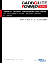
TUNE PROGRAM
Enter program mode and select TUNE
The controller will alternately display TUNE and
oFF
.
Press and hold ✱ and press ▲ once,
The controller will alternately display TUNE and
on
.
Exit program mode.
The TUNE program will now start. The controller will
alternately display TUNE and the process temperature
as it climbs to setpoint.
Note: During tuning, the main setpoint (SP1) LED will flash.
Temp
Setpoint
Cycle
75% SP
Start
TUNE
TUNE
Tuning DAC
PID
1
1
/4 on/off tuning
cycles
New PID
values
entered
Time
(100% output)
7

Autotune
The TUNE AT SETPOINT program will now start. The
controller will alternately display TUNE and the
process temperature.
Note: During tuning the main setpoint (SP1) LED will flash.
When the TUNE AT SETPOINT program is complete the
alternating display stops and the process temperature is
displayed. The PID values are entered automatically. The
process temperature will rise to setpoint and control should
be stable. If not, this may be because optimum cycle time
is not automatically implemented. To set the cycle time see
PROPORTIONAL CYCLE-TIME.
When the TUNE program is complete the alternating
display stops and the process temperature is displayed.
The PID values are entered automatically. The process
temperature will rise to setpoint and control should be
stable. If not, this may be because optimum cycle time is
not automatically implemented. To set the cycle time see
PROPORTIONAL CYCLE-TIME.
TUNE AT SETPOINT PROGRAM
Enter program mode and select TUNE
The controller will alternately display TUNE and
oFF
.
Select TUNE
At.SP
.
The controller will alternately display TUNE and
At.SP
.
Exit program mode.
Temp
Setpoint
Start
TUNE
Tuning
PID
1
3
/4 on/off tuning
cycles
New PID
values
entered
Time
(100% output)
AT.SP
Overshoot
during tuning
Prop band
REMINDER OF INSTRUMENT ADJUSTMENTS
Press ▲ ▼ together for 3 seconds for program entry or exit.
Press ▲ or ▼ to scroll through functions.
Press ✱ ▲ together or ✱ ▼ together to change levels or
alter options.
Note: If in difficulty by becoming “lost” in program mode,
press ▲ and ▼ together for 3 seconds to return
to display mode, check the Menu Navigation
summary above and try again.
8

Proportional cycle-time
The choice of cycle-time is influenced by the external
switching device or load. eg. contactor, SSR, valve. A setting
that is too long for the process will cause oscillation and a
setting that is too short will cause unnecessary wear to an
electro-mechanical switching device.
CYCLE-TIME SELECTION METHODS
The following methods of cycle-time selection may be used:
Autotune calculated
After Autotune has been run and completed the calculated
cycle-time can be manually accepted or adjusted to suit the
switching device. For selection method see Select Autotune
Calculated Cycle-time.
Pre-select Autotune cycle-time
The controller can be programmed to automatically accept
any calculated Autotune cycle-time. For selection method
see Pre-Select Automatic Acceptance of Any Autotune
Cycle-time, page 10.
Pre-select before Autotune
The controller can be programmed manually with any
cycle-time between 0.1 and 81 sec. This cycle-time will not
be changed by any Autotune functions. For selection method
see Pre-Select Cycle-time Before Autotune, page 10.
Factory set
To use the 20 sec factory set cycle-time no action is needed
whether autotune is used or not.
CYCLE-TIME RECOMMENDATIONS
To Select AUTOTUNE CALCULATED CYCLE-TIME
On completion of Autotune enter program mode.
Select CYC.T
The controller will now alternately display CYC.T and
20
(the factory setting).
To view the calculated optimum cycle-time press and hold
the ✱ button then press and hold ▼ until indexing stops.
The controller will display the calculated cycle-time
CYC.T and eg.
A16
. This indicates that the calculated
cycle-time is 16 seconds.
PROPORTIONAL CYCLE-TIME
9
Output
Device
Load max
(resistive)
Factory
Setting
Recommended
Minimum
Internal relay
rLY/rLY1
Internal relay
rLY2
20 seconds
20 seconds
20 seconds
10 seconds
2A/250 Vac
1A/250 Vac
Externally
fitted SSR
(n/a)
Solid state
drives
SSd/SSd1/SSd2
10 seconds
0.1 seconds

If this cycle-time is suitable press and hold both ▲ and ▼
buttons for 3 seconds to enter it into the controllers
memory.
If the calculated cycle-time is not compatible with the
switching device press and hold the ✱ button then press
and hold ▲ or ▼ until a more suitable cycle-time is
displayed. Release the buttons, then press and hold both
▲ and ▼ buttons for 3 seconds to enter it into the
controllers memory.
Pre-Select Automatic Acceptance of Any Autotune
Cycle-time
Before selecting Autotune, enter program mode.
Select CYC.T
Press and hold the ✱ button then press and hold ▼ until
indexing stops and
A- -
is displayed.
Note:
A- -
indicates that no cycle-time exists.
Press and hold ▼ to scroll to TUNE
The controller will now alternately display TUNE and
oFF
. Press and hold the ✱ button and use ▲ to select
either
on
or
At.SP
. Release ▲.
The controller will now run Autotune and will accept the
calculated cycle-time.
To Pre-Select Cycle-time Before Autotune
Before selecting Autotune, enter program mode.
Select CYC.T
Press and hold the ✱ button, then press ▲ to increase
or ▼ to decrease the displayed cycle-time. Release
buttons when required value is displayed.
Select TUNE or index to another function then exit
program mode.
Proportional cycle-time
10
81
ON.OF
0.1
20
A --
Factory setting
ON/OFF
Autotune calculated
cycle-time
Manual settings
Seconds
✱ ▼
✱ ▲
Proportional Cycle-time (continued)

Programmer
RAMP-SOAK
This feature enables the controller to ramp up or down from
current temperature to a target setpoint at a pre-
determined rate. It then controls at the target setpoint for
an adjustable soak period before switching off the heat
output.
Set
Ramp rate (0 to 9995 deg/hour)
Press ▲ and ▼ buttons for 3 seconds to enter program
entry point TUNE
Press ▲ to scroll to SPRR
Press and hold ✱, then press ▲ or ▼ to scroll to required
value.
Set Soak (if required) 0 to 1440 minutes
Press ▲ to scroll to SOAK
Press and hold ✱, then press ▲ or ▼ to scroll to required
soak period.
Set Ramp On (Off) : On : hold
Press ▲ to scroll to SPRN
Press and hold ✱, then press ▲ to select On
Exit program to enter settings into memory and commence
ramp to target setpoint.
Notes
In Ramp on configuration, if power is removed from the
controller, the Ramp will re-start when power is restored.
The Ramp hold option suspends the ramp at its last value.
If no Soak period has been set, control at target setpoint
continues indefinitely.
SP2 deviation alarms follow the ramp setpoint and can be
used to alarm “out of limits” ramp rate.
WARNING
The Soak timer is triggered when the ramp setpoint reaches
the target setpoint. If the ramp rate is set too fast for the
process, the Soak timer will be triggered before the process
temperature reaches the target setpoint.
PROGRAMMER
Target
setpoint
Deg.
Ramp °/hour
Time
Soak
Target
setpoint
Deg.
Ramp °/hour
Time
Soak
11

The second setpoint SP2 can be used to trigger an alarm
or as a proportional control output.
TO CONFIGURE SP2 AS AN ALARM
Enter program mode.
Select level 2 then SP2.A , followed by the required
option below:
dV.hi
sets off alarm signal when temperature rises above
a pre-set temperature above the setpoint.
dV.Lo
sets off alarm signal when temperature falls below
a pre-set temperature below the setpoint.
bAnd
sets off alarm signal when temperature rises above
or falls below a pre-set temperature above or
below the setpoint.
FS.hi
sets off alarm signal when the temperature rises
above setpoint to a pre-set temperature above
scale minimum.
FS.Lo
sets off alarm signal when the temperature falls
below setpoint to a pre-set temperature above
scale minimum.
Select level 1 and select SET.2 and set the required
setpoint value (y°).
If the factory set hysteresis 2.0°C/3.6°F is unsuitable:
Index to BND.2 and adjust the setting.
Check CYC.2 is set to
on.oF
(for alarm).
Exit program mode. SP2 is now operational as an alarm.
CooL
see heat-cool configuration, page 23.
Second Setpoint
SECOND SETPOINT (SP2)
Y°
✱
✱
✱
✱
Deviation
high alarm
Deviation
low alarm
Deviation
band alarm
Alarm
state
SP
setpoint
Y°
Y°
Y°
SP
setpoint
SP
setpoint
Y°= SP2
set value
Y°
✱
✱
Full scale
high alarm
Full scale
low alarm
SP
setpoint
SP
setpoint
Y°
12

Second Setpoint
SUBSIDIARY SP2 MODE: SP2.B Latch/sequence or
non-linear cool.
Latch alarm
LtCh
When activated, the alarm latches until manually reset, even
though the alarm condition may have disappeared.
Sequence alarm
hoLd
When
hoLd
is selected, in any alarm mode, it prevents an
alarm signal on power-up. The alarm is enabled only when
the process temperature reaches setpoint.
TO CONFIGURE SP2 AS A PROPORTIONAL
CONTROL OUTPUT
In level 2 select SP2.A , then select the required option.
In level 1 select BND.2 and then set the required
proportional band.
In level 1 select SET.2 and then set the setpoint (SP2)
value (y°).
SP2 OUTPUT AND LED INDICATION STATES - IN
ALARM CONDITION
SP2 ALARM ANNUNCIATOR
When an SP2 alarm mode is selected in SP2.A the alarm
annunciator
-AL-
is displayed, alternating with the process
temperature, during alarm condition.
Note: The annunciator may be disabled by selecting
function NO.AL , option
on
in level 4.
SP2 in cool strategy
(See heat-cool configuration in ADVANCED SETTINGS page 23).
✱
Without sequence
alarm
Alarms on
power up
SP
setpoint
Y°
✱
Y°
SP
setpoint
SP
setpoint
SP
setpoint
No alarm on
power up
With sequence alarm
Alarm
enabled
Alarm operates
normally
Alarm type ON-OFF
operating mode
Proportional
operating mode
FS.HI
COOL
FS.LO
BAND
DV.LO
DV.HI
Deviation
Full scale
Strategy
SP2
Output state
SP2
LED state
SP2
Output state
SP2
LED state
BAND
: on-off mode only
Output ON
(Relay or SSd energised)
Output OFF
(Relay or SSd de-energised)
LED ON
Temperature above setpoint
13

Error Messages
ERROR MESSAGES
Temp
Setpoint
Cycle
75% SP
Start
TUNE
TUNE
Tuning
DAC
PID
New PID
values
entered
Time
(100% output)
oS 1
oS 2
Ct A
Ct b
Ct 3
Ct 4
uS
Ct 1
Ct 2
SENSOR FAULT
Display flashing: INPT and
FaiL
Indicates: thermocouple burnout RTD/Pt100 open or
short circuit or negative over-range.
Action: Check sensor/wiring
NON-VOLATILE MEMORY ERROR
Display flashing: DATA and
FaiL
Action: De-power briefly. Replace unit if problem
persists
MANUAL POWER ERROR
Display flashing: DATA and
FaiL
SP1 set to ON/OFF in
CYC.t
Action: Select proportional mode
IMMEDIATE FAIL ON AUTOTUNE START
Display flashing: (setpoint), TUNE and
FaiL
1. No setpoint entered
Action: Enter setpoint
2. SP1 set to ON/OFF in CYC.T
Action: Select proportional mode
Note: To reset and clear error press ▲▼ together briefly to
cancel message.
FAIL LATER DURING AUTOTUNE CYCLE
The thermal characteristics of the load exceed the Autotune
algorithm limits. The failure point indicated by any display
0.0 in TECH eg. Ctb = 0.0 see diagram below.
Action: 1. Change the conditions. eg. raise setpoint
2. Try TUNE
At.SP
3. Check SP1.P percentage power
(see IMPROVING CONTROL ACCURACY)
4. If the error message persists, call Omega for advice.
READING AUTOTUNE TUNING CYCLE
RESULTS IN
TECH
1. Index to TECH , release ▲ or ▼, display will
alternately display TECH and
Ct.A
2. Press and hold ✱, the display will alternate
Ct.A
and value
(eg. 10.4)
3. Keep ✱ pressed and press ▲ once, the display
Ct.B
and
value (eg. 19.6)
4. Repeat step 3 above to view:
Ct 1, Ct 2, Ct 3, Ct 4, oS 1, uS and oS 2.
Autotune tuning data and limits
14

Improving Control Accuracy
IMPROVING CONTROL ACCURACY
Temp
Maximum
Time
Variance
VAr°
hi°
±0.1°
Minimum
Lo°
The following functions are to assist engineers with
machine development, commissioning and troubleshooting.
SP1.P READ SP1 OUTPUT PERCENTAGE POWER
Poor control may be due to incorrectly sized heaters.
SP1.P (Level 2) constantly displays the output
percentage power applied, which at normal setpoint should
ideally be within 20 - 80% to achieve stable control.
CHEK
CONTROL ACCURACY MONITOR
This measures the control stability, to within 0.1 °C/°F.
The monitor is started using CHEK (Level 3) and the
variance (deviation), maximum and minimum temperatures
are displayed and constantly updated in READ
Using the CHEK Control accuracy monitor
To start the monitor select CHEK
on
Note: During monitoring either return to normal operation
or remain in program mode.
To view monitor readings: index to READ
The display will alternate between READ and
Var°
Press and hold ✱, the display will alternate between
Var°
and the variance displayed in degrees (e.g. 0.6)
Press and hold ✱ and press ▲ once, the display will
alternate between
VAr°
and the maximum
hi°
displayed
in degrees (e.g. 320.3)
Press and hold ✱ and press ▲ once, the display will
alternate between
VAr°
and the minimum
Lo°
displayed
in degrees (e.g. 319.7)
CHEK
oFF
stops monitor retaining readings
CHEK
on
resets readings.
On de-powering CHEK resets to
oFF
and READ
is zeroed.
15
/