GA-946-DS3/S3 Motherboard - 16 -
English
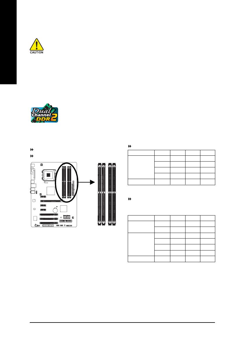
1-4 Installing the Memory
Read the following guidelines before you begin to install the memory:
• Make sure that the motherboard supports the memory. It is recommended that memory of
the same capacity, brand, speed, and chips be used.
(Go to GIGABYTE's website for the latest memory support list.)
• Always turn off the computer and unplug the power cord from the power outlet before
installing the memory to prevent hardware damage.
• Memory modules have a foolproof design. A memory module can be installed in only one
direction. If you are unable to insert the memory, switch the direction.
DDRII1
DDRII2
DDRII3
DDRII4
1-4-1 Dual Channel Memory Configuration
This motherboard provides four DDR2 memory sockets and supports Dual Channel
Technology. After the memory is installed, the BIOS will automatically detect the
specifications and capacity of the memory. Enabling Dual Channel memory mode
will double the original memory bandwidth.
The four DDR2 memory sockets are divided into two channels and each channel has two memory
sockets as following:
Channel 0: DDRII1, DDRII2
Channel 1: DDRII3, DDRII4
Due to chipset limitation, read the following guidelines before installing the memory in Dual Channel mode.
1. Dual Channel mode cannot be enabled if only one DDR2 memory module is installed.
2. When enabling Dual Channel mode with two or four memory modules, it is recommended that
memory of the same capacity, brand, speed, and chips be used and installed according to the
configurations in the first table for optimum performance.
3. Because of chipset limitations, do not populate both DIMM sockets of the same channel
(e.g. DDRII1 and DDRII2) with double-sided memory modules to prevent system's failure to
start or incorrect detection of memory modules.
Dual Channel Memory Configurations Table
(SS=Single-Sided, DS=Double-Sided, "- -"=No Memory)
Two Modules
Three Modules
Four Modules
DDRII1 DDRII2 DDRII3 DDRII4
SS SS - - - -
- - - - SS SS
SS SS DS/SS - -
SS SS - - DS/SS
DS/SS - - SS SS
- - DS/SS SS SS
SS SS SS SS
Memory configurations below will cause DDR2 667
memory to operate at 533 MHz (with 1066/800 MHz FSB CPU)
and DDR2 533 at 400 MHz (with 800 MHz FSB CPU).
(SS=Single-Sided, DS=Double-Sided, "- -"=No Memory)
Two Modules
Four Modules
DDRII1 DDRII2 DDRII3 DDRII4
DS/SS - - DS/SS - -
DS/SS - - - - DS/SS
- - DS/SS DS/SS - -
- - DS/SS - - DS/SS
SS SS SS SS


