Page is loading ...

Specifications
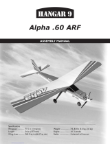
Wingspan: 62 in (1570mm)
Length: 62.5 in (1580mm)
Wing Area: 740 sq in (47.7 sq dm)
Weight w/o Battery: 9.2–10.5 lb (4.2–4.7 kg)
Weight w/Battery: 7.75–8.5 lb (3.5–3.9 kg)
Deuces Wild ARF
Assembly Manual

2 E-flite Deuces Wild Assembly Manual
Introduction
The Deuces Wild 25e2 ARF is the first twin and the first sport
plane in the Platinum Series. It is easier to fly than most other
twins and exhibits gentle flight characteristics. Along with the
superior features that come with every E-flite Platinum Series
plane, the Deuces Wild is full of enhanced details. All flight
control surfaces are installed, pushrods are pre-bent and
ready for installation and it includes optional gear doors.
The Deuces Wild also comes with a unique wing design in
that it utilizes two Selig airfoils to give it excellent performance
at high and low speeds, while also giving the pilot gentle
stall characteristics. It was even designed with the unthinkable
in mind—the loss of an engine. In the event of an engine
loss, this aircraft is still easily flyable. The lightweight sturdy
frame is constructed of balsa and plywood and covered in
genuineHangar 9 UltraCote for added durability. The bolt-on
tail assembly and removable wing panels are designed for
quick building and easy storage.
Flight characteristics, aerobatic capabilities and amazing
details—any experienced modeler would bet on the
Deuces Wild.
Using the Manual
This manual is divided into sections to help make assembly
easier to understand, and to provide breaks between each
major section. In addition, check boxes have been placed next
to each step to keep track of each step completed. Steps with
a single circle () are performed once, while steps with two
circles ( ) indicate that the step will require repeating, such
as for a right or left wing panel, two servos, etc.
Remember to take your time and follow the directions.
Table of Contents
Introduction ......................................................................... 2
Using the Manual ................................................................ 2
Contents of Kit/Parts Layout ................................................. 3
Recommended Radio Equipment .......................................... 3
Required Tools and Adhesives .............................................. 4
Notes Regarding Servos and ESC ........................................ 4
Brushless Outrunner Setup, Power 25 ................................... 4
Brushless Outrunner Setup, Power 32 ................................... 4
Optional Accessories ........................................................... 4
Covering Colors .................................................................. 4
Note on Lithium Polymer Batteries ........................................ 5
Warning ............................................................................. 5
Fuselage Radio Installation ................................................... 5
Tail Attachment.................................................................... 8
Rudder and Elevator linkage Installation ............................. 10
Aileron Servo Installation ................................................... 16
Flap Servo Installation ....................................................... 21
Fixed Gear Installation ....................................................... 26
Retract Gear Installation ..................................................... 31
Retract Servo Installation .................................................... 40
Aileron and Throttle Servo Extensions ................................. 46
Power 25 Motor Installation ............................................... 48
Power 32 Motor Installation ............................................... 49
Propeller and Spinner Installation ....................................... 52
Wing Installation ............................................................... 56
Canopy and Gear Door Installation .................................... 57
Center of Gravity and Nose Cone Installation ..................... 59
Control Throws .................................................................. 60
Range Test Your Radio ....................................................... 61
Preflight ............................................................................ 61
Flying Your Deuces Wild .................................................... 62
Safety, Precautions, and Warnings ..................................... 63
Warranty Information ........................................................ 63
Instructions for Disposal of WEEE by
Users in the European Union ................................... 65
2008 Official AMA National Model Aircraft Safety Code ... 66

3E-flite Deuces Wild Assembly Manual
Contents of Kit/Parts Layout
Replacement Parts
EFL4551L Left Wing Panel
EFL4551C Center Wing Panel
EFL4551R Right Wing Panel
EFL4552 Fuselage
EFL4553 Tail Set
EFL4554L Left Nacelle
EFL4554R Right Nacelle
EFL4555 Landing Gear
EFL4556 Canopy
EFL4557 Pushrod Set
EFL4558 Spinner (Left Hand)
EFL4559 Spinner (Right Hand)
EFL4560 Wing Tube
EFL4561 Nose Cone
EFL4563 Strut Covers
Recommended Radio Equipment
You will need a minimum 6-channel transmitter, receiver, and
six or seven servos. You can choose to purchase a complete
radio system. If you are using an existing transmitter, just purchase
the other required equipment separately. We recommend the
crystalfree, interference-free Spektrum
™
DX6i 2.4GHz DSM
®
6-channel system. If using your own transmitter, we recommend
the JR SPORT
™
standard servos.
If you own the Spektrum DX6i radio, just add the AR6200 DSM2
™
6-channel receiver and six JR SPORT ST47 Standard Servos.
Complete Radio System
SPM6600 DX6i DSM2 6CH system
SPM2710 DX7 DSM2 7CH system
Or Purchase Separately
SPMAR6200 AR6200 DSM2 6-Channel Full-Range
Receiver (for DX6i or DX7)
SPM6070 AR7000 DSM2 7-Channel Full Range
Receiver (for DX6i or DX7)
And
JSP20050 ST47 Standard Servo (6, 7 w/retracts)
JSP98020 6-inch Y-Harness (3)
EFLREX3L 3-inch Extension, Lightweight (4)
EFLREX9L 9-inch Extension, Lightweight (2)
EFLREX12L 12-inch Extension, Lightweight (2)
The Spektrum trademark is used with
permission of Bachmann Industries, Inc.

4 E-flite Deuces Wild Assembly Manual
Required Tools and Adhesives
Tools & Equipment
Felt-tipped pen Ball driver: 3/32-inch
Low-tack masking tape Mixing sticks
Paper towels Pin drill
Rubbing alcohol Mixing cups
Hobby knife (#11 blade) Pliers
Phillips screwdriver: #1, #2 Side cutters
Sandpaper Nut driver: 1/4-inch
Pencil Drill
Covering iron Flat screwdriver
Dental floss Scissors
Rotary tool w/high speed cutting bit
Drill bit: 1/16-inch (1.5mm), 5/64-inch (2mm),
3/32-inch (2.5mm), 3/16-inch (5mm)
Adhesives
Thin CA Medium CA
Threadlock 6-Minute Epoxy (HAN8000)
Canopy glue Silicone adhesive
Notes Regarding Servos and ESC
WARNING: Use of servos other than those we suggest may
overload the BEC of the recommended Electronic Speed Control
(ESC). Please use only the servos listed when utilizing the
recommended ESC’s BEC, or the use of a separate BEC (like the
UBEC) or receiver battery pack when using other servos.
Brushless Outrunner Setup, Power 25
EFLM4025A (2 req) Power 25 Brushless Outrunner Motor
870Kv
EFLA1060 (2 req) 60-Amp Pro Switch-Mode BEC
Brushless ESC
EFLB32003S (2 req) E-flite 3S 11.1V 3200mAh 20C Li-Po
APC12080E (1 req) 12x8 Electric Propeller
APC12080EP (1 req) 12x8 Electric Pusher Propeller
Brushless Outrunner Setup, Power 32
EFLM4032A (2 req) Power 32 Brushless Outrunner Motor,
770Kv
EFLA1060 (2 req) 60-Amp Pro Switch-Mode BEC
Brushless ESC
THP33004SXV (2 req) 4S 14.4V 3300mAh 25C Li-Po battery
APC13065E (1 req) 13x6.5 Electric Propeller
APC13065EP (1 req) 13x6.5 Electric Pusher Propeller
Optional Accessories
EFLA110 Power Meter
EFLC505 Intelligent 1- to 5-Cell Balancing Charger
EFL4562 Cockpit Kit, Deuces Wild ARF
EFL4565 Retracts, Deuces Wild ARF
DUB141 3/16-inch Wheel Collars (required for
retract installation)
Covering Colors
White HANU870
Flame Red HANU883
Black HANU874

5E-flite Deuces Wild Assembly Manual
Note on Lithium Polymer Batteries
Lithium Polymer batteries are significantly more
volatile than alkaline or Ni-Cd/Ni-MH batteries used
in RC applications. All manufacturer’s instructions
and warnings must be followed closely. Mishandling
of Li-Po batteries can result in fire. Always follow the
manufacturer’s instructions when disposing of Lithium
Polymer batteries.
Warning
An RC aircraft is not a toy! If misused, it can cause serious
bodily harm and damage to property. Fly only in open areas,
preferably at AMA (Academy of Model Aeronautics) approved
flying sites, following all instructions included with your radio.
Keep loose items that can get entangled in the propeller away
from the prop, including loose clothing, or other objects such as
pencils and screwdrivers. Especially keep your hands away from
the propeller.
Fuselage Radio Installation
Required Parts
Fuselage Servo w/hardware (3)
Hook and loop tape Receiver
3-inch (76mm) servo extension (3) (4 for optional retracts)
Required Tools and Adhesives
Pin drill Drill bit: 1/16-inch (1.5mm)
Thin CA Phillips screwdriver: #1
Pencil
1. Install the servo grommets and brass eyelets into your
servos at this time. We feel it is easiest to prepare all the
servos to save time later. If so, you will need all 6 or 7
servos for this step.

6 E-flite Deuces Wild Assembly Manual
2. Position the elevator servo in the fuselage. Use a pencil
to transfer the locations for the servo mounting screws to
the servo tray.
3. Use a pin drill and 1/16-inch (1.5mm) drill bit to drill
the four holes for the servo mounting screws.
4. Apply 2–3 drops of thin CA into each of the holes to
harden the surrounding wood. This will provide a harder
surface for the screws to bite into when installed.
5. Secure the elevator servo in the fuselage using
the hardware provided with the servo and a #1
Phillips screwdriver.

7E-flite Deuces Wild Assembly Manual
6. Repeat all of the previous steps to install the rudder
servo and steering servo in the fuselage. Note that the
steering servo is in the center location when installed.
Please note the orientation of the servos in the fuselage.
7. Use hook and loop tape to install the receiver into the
fuselage. When installing a remote receiver, place it as
far away from the main receiver as possible, aligning the
antennas perpendicular to those of the main receiver.
Note: If you are using a standard 72MHz receiver, an
antenna tube has been installed in the fuselage to route
the antenna wire to the rear of the fuselage. Never cut
the receiver antenna as this will greatly reduce the range
of your radio system.

8 E-flite Deuces Wild Assembly Manual
8. Plug a 3-inch (76mm) servo extension into the throttle,
aileron and flap ports on the receiver at this time. This
will make it easier to plug the leads that will be installed
in the wing later while assembling your aircraft.
Note: If you are installing retracts, plug a 3-inch (76mm)
extension into the port marked GEAR at this time as well.
Tail Attachment
Required Parts
Rudder/fin Elevator/stabilizer
Fuselage assembly Nylon control horn
4-40 lock nut (2) #4 washer (2)
Required Tools and Adhesives
Nut driver: 1/4-inch
1. Thread the nylon control horn onto the rudder
torque rod. You will thread this on until the end of
the rod is flush with the nylon control horn.

9E-flite Deuces Wild Assembly Manual
2. Slide the threaded rods from the fin into the holes in
the stabilizer. The fin will fit flush against the stabilizer
when installed.
3. Slide the threaded rods into the holes in the rear
of the fuselage.
4. Using a 1/4-inch nut driver, secure the tail assembly
to the fuselage using two 4-40 lock nuts and two #4
washers. Do not over-tighten the nuts and damage the
fuselage. At this time the Rudder/Fin, Stab/Elevator, and
Fuselage should fit tight against each other.

10 E-flite Deuces Wild Assembly Manual
Rudder and Elevator linkage Installation
Required Parts
Fuselage assembly Nylon clevis (2)
Silicone clevis retainer (2) Nylon pushrod keeper (2)
29
3
/
4
-inch (755mm) pushrod wire (2)
Required Tools and Adhesives
Pin drill Drill bit: 5/64-inch (2mm)
Felt-tipped pen Pliers
Side cutters Phillips screwdriver: #1
1. Thread a clevis onto one of the 29
3
/
4
-inch (755mm)
pushrod wires. Make sure to slide a silicone clevis
retainer onto the clevis before threading it onto the
pushrod wire.
2. Slide the pushrod wire into the pre-installed pushrod
tube on the same side of the fuselage as the elevator
control horn. Attach the clevis to the elevator control horn
in the middle hole.
3. Use a pin drill and 5/64-inch (2mm) drill bit to
enlarge the outer hole of the elevator servo horn.

11E-flite Deuces Wild Assembly Manual
4. Center the elevator servo using the radio system. With
the elevator in the neutral position, use a felt-tipped pen
to mark the pushrod wire where it crosses the outside
hole on the servo horn.
5. Use pliers to bend the pushrod wire 90 degrees at the
mark made in the last step.
Note: Use side cutters to trim any arms that will interfere
with the operation of the rudder servo.
6. Using a #1 Phillips to remove the servo horn from
the servo. Slide the servo horn onto the pushrod wire
with the splined part of the horn that fits onto the servo
toward the bend.

12 E-flite Deuces Wild Assembly Manual
7. Next, slide the pushrod keeper onto the wire. Slide
the horn and keeper down so the horn it tight against
the bend.
8. The notch in the pushrod keeper will snap onto the
pushrod wire. This will keep the pushrod secure on the
servo horn. You may need to use pliers to apply enough
force to snap the pushrod keeper onto the wire.
9. Use side cutters to remove any excess wire that
extends beyond the connector. Leave a small amount of
wire to prevent the keeper from popping off accidentally.
10. Rotate the pushrod wire 90 degrees so the servo
horn aligns with the servo output shaft. Use a #1 Phillips
screwdriver to reattach the servo horn to the elevator
servo at the center position.

13E-flite Deuces Wild Assembly Manual
11. Thread a clevis onto one of the 29
3
/
4
-inch (755mm)
pushrod wires. Make sure to slide a silicone clevis
retainer onto the clevis before threading it onto the
pushrod wire.
12. Slide the wire into the rudder pushrod tube and
connect the clevis to the rudder servo horn. Plug a
Y-harness into the receiver rudder port of your receiver.
The rudder and nose wheel steering servo will plug into
this Y-harness.
Note: Use side cutters to trim any arms that will interfere
with the operation of the rudder servo.
13. Center the rudder servo using the radio system. With
the rudder in the center position, use a felt-tipped pen to
mark the pushrod where it crosses the hole in the rudder
control horn.

14 E-flite Deuces Wild Assembly Manual
14. Make a 90 degree bend in the pushrod wire at the
mark you made in Step 10.
15. Slide the pushrod wire through the hole in the rudder
control horn. You will need to rotate the horn so it can
be aligned with the pushrod for this step. Once the wire
has been inserted, you can rotate the control horn so it is
aligned with the pushrod wire.

15E-flite Deuces Wild Assembly Manual
16. Slide the pushrod keeper onto the wire. Position the
wire so the bend in the wire is snug against the control
horn as shown.
17. The notch in the pushrod keeper will snap onto the
pushrod wire. This will keep the pushrod secure. You
may need to use pliers to apply enough force to snap the
pushrod keeper onto the wire.
18. Use side cutters to remove any excess wire that
extends beyond the connector. Leave a small amount of
wire to prevent the keeper from popping off accidentally.
19. Remove the pushrod keeper and rotate the pushrod
180 degrees. Insert the pushrod into the nylon control
horn and reinstall the pushrod keeper. This is necessary
so the keeper doesn't bind against the fuselage during
the operation of the rudder.

16 E-flite Deuces Wild Assembly Manual
Aileron Servo Installation
Required Parts
Wing panel (right and left) Servo hatch (right and left)
Servo mounting block (4) Servo w/hardware (2)
Nylon clevis (2) Silicone clevis retainer (2)
Nylon pushrod keeper (2)
2mm x 10mm self-tapping screw (8)
4 1/4-inch (108mm) aileron pushrod wire (2)
Required Tools and Adhesives
Pencil 6-minute epoxy
Drill Pin drill
Phillips screwdriver: #1 Thin CA
Felt-tipped pen Pliers
Mixing cups Mixing sticks
Side cutters Sandpaper
Drill bit: 1/16-inch (1.5mm), 5/64-inch (2mm)
1. Use sandpaper to roughen the ends of the four servo
mounting blocks. Doing so will allow the epoxy applied
to them in the next step a better surface to adhere to.
2. Use 6-minute epoxy to secure the servo mounting
blocks on the servo hatch. The positions for the blocks
have been etched onto the hatch for your convenience.

17E-flite Deuces Wild Assembly Manual
3. Position the servo between the blocks. Leave a small
gap between the servo and hatch to prevent the transfer
of vibration from the airframe into the servo. Use a pencil
to transfer the locations for the servo mounting screws
onto the servo mounting blocks.
4. Use a drill and 1/16-inch (1.5mm) drill bit to drill the
four holes for the servo mounting screws.
5. Apply 2–3 drops of thin CA into the holes to harden
the surrounding wood. This provides a hard surface for
the screws, making them more secure when installed.

18 E-flite Deuces Wild Assembly Manual
6. Attach the servo to the servo mounting blocks
using the screws provided with the servo and a
#1 Phillips screwdriver.
7. Remove the servo horn using a #1 Phillips screwdriver
and trim away any unused arms from the servo horn with
side cutters. Once complete reinstall the servo horn using
a #1 Phillips screwdriver. Use a pin drill and 5/64-inch
(2mm) drill bit to enlarge to outer hole in the remaining
servo arm as shown.
8. Tie the string that has been installed in the outer wing
panel to the servo lead.
9. Use the string to pull the servo lead through the wing
panel as shown.

19E-flite Deuces Wild Assembly Manual
10. Secure the servo hatch to the wing using four 2mm x
10mm self tapping screws and a #1 Phillips screwdriver.
11. Slide a silicone clevis retainer onto a nylon clevis.
Thread the clevis onto the 4
1
/
4
-inch (108mm) aileron
pushrod wire.
12. Attach the clevis to the aileron control horn
center hole.
13. Use the radio system to center the aileron servo.
With the aileron in the center position, use a felt-tipped
pen to mark the pushrod where it crosses the hole in the
aileron servo arm.

20 E-flite Deuces Wild Assembly Manual
14. Use pliers to bend the pushrod 90-degrees at the
mark made in the previous step.
15. Slide the pushrod wire into the servo arm.
16. Secure the pushrod wire to the servo horn using
a nylon pushrod keeper. Use side cutters to remove
any excess pushrod wire that would interfere with the
operation of the aileron.
17. Repeat Steps 2 through 16 to install the remaining
aileron servo and linkage.
/