ONKYO (HTP-588) Owner's manual

Category
Home audio sets
Type
Owner's manual

This manual is also suitable for

En-1
En
* 2 9 4 0 2 0 1 1 *
F1503-0
5.1.2ch Home Theater Speaker Package
Make sure you have the following accessories.
Front & Height Speakers (SKF-594)
Center Speaker (SKC-594)
*1
Configuration of the rubber stoppers may be different from the
figure, such as being 2 sheets instead of 1 sheet, but the total
number will be same.
Surround Speakers (SKR-594)
Powered Subwoofer (SKW-658)
Front & Height Speakers (SKF-594)
Center Speaker (SKC-594)
Surround Speakers (SKR-594)
Supplied Accessories
Front & Height speakers Speaker cables
10 ft. (3.0 m)
Center speaker Speaker cable
10 ft. (3.0 m)
4 rubber stoppers*1
(Left) (Right)
(White)
(Red)
(Brown)
(Tan)
(Green)
Subwoofer RCA cable
10 ft. (3.0 m)
4 floor pads
(Left) (Right)
(Blue)
(Gray)
Part Names
Speaker terminals
(Height)
Keyhole slot
Speaker terminals
(Front)
Speaker units
Speaker terminals
Keyhole slots
Speaker terminals
Keyhole slot
HTP-588
Speaker cables 26 ft. (8.0 m)
Surround speakers
HTP-588_En_SN29402011_1503xx.book 1 ページ 2015年3月12日 木曜日 午後2時56
En-2
Caution
The front grilles are not designed to be removed so do not
attempt to remove them forcibly, as this will damage
them.
Powered Subwoofer (SKW-658)
Front
.
Rear
Note
The Auto Standby function turns the subwoofer on when the
input signal exceeds a certain level. If the Auto Standby function
does not work reliably, try slightly increasing or decreasing the
subwoofer output level on your receiver.
Using the Rubber Stoppers for a More Stable
Platform
We recommend using the supplied rubber stoppers to
achieve the best possible sound from your speakers. The
rubber stoppers prevent the speakers from moving, then
provide a more stable platform. Use rubber stoppers for the
center speaker.
Using the Floor Pads for Subwoofer
If the subwoofer is placed on a hard floor (wood, vinyl,
tile, etc.) and playback is very loud, the subwoofer’s feet
may damage the flooring. To prevent this, place the
supplied pads underneath the subwoofer’s feet. The pads
also provide a stable base for the subwoofer.
Setting the Subwoofer Level
To set the level of the subwoofer, use the
OUTPUT LEVEL control. Set it so that bass
sounds are evenly balanced with the treble sounds
from the other speakers. Because our ears are less
sensitive to very low bass sounds, there’s a temptation to
set the level of the subwoofer too high. As a rule of thumb,
set the subwoofer level to what you think is the optimal
level, and then back it off slightly.
Wall Mounting
To mount the front/surround speakers vertically, use the
keyhole slot shown to hang each speaker on a screw that’s
securely screwed into the wall.
To mount the center speaker horizontally, use the two
keyhole slots shown to hang the speaker on two screws that
are securely screwed into the wall.
Status indicator
Off: Subwoofer in standby mode or
disconnected from power source
Blue:Subwoofer on
The status indicator lights blue when
low frequency sound is being passed
through the speaker.
The indicator does not light in the
normal dialog or high frequency
sound.
The indicator does not indicate that
power supply of the subwoofer has
turned on.
With the Auto Standby function, the
SKW-658 automatically turns on
when an input signal is detected in
standby mode. When there’s no input
signal for a while, the SKW-658
automatically enters standby mode.
To AC outlet
OUTPUT LEVEL control
This control is used to adjust the
volume of the subwoofer.
LINE INPUT
This RCA input should be
connected to the subwoofer pre
out on your AV receiver with
supplied RCA cable.
Before Using the Home Theater
Speaker Package
Rubber stoppers
Bottom of the
SKC-594
Floor pad
SKF-594
SKR-594
Keyhole slots for
wall mounting
Keyhole slots for wall mounting
7-7/8" (200 mm)
SKC-594
HTP-588_En_SN29402011_1503xx.book 2 ページ 2015年3月12日 木曜日 午後2時56
En-3
Caution
A mounting screw’s ability to support a
speaker depends on how well it’s
anchored to the wall. If you have
hollow walls, screw each mounting
screw into a stud. If there are no studs,
or the walls are solid, use suitable wall
anchors. Use screws with a head
diameter of 5/16" (8 mm) or less and a shank diameter of
1/8" (4 mm) or less. With hollow walls, use a cable/pipe
detector to check for any power cables or water pipes
before making any holes.
• Leave a gap of about 3/16" (5 mm) between the wall and
the base of the screw head, as shown (We recommend
that you consult a home installation professional).
The Home Theater means that you can enjoy surround
sound with a real sense of movement in your own home —
just like being in a movie theater or concert hall.
.
Speaker Connection Precautions
Read the following before connecting your speakers:
• Turn off your receiver before making any connections.
• Pay close attention to speaker wiring polarity.
Connect positive (+) terminals to only
positive (+) terminals, and negative (–)
terminals to only negative (–) terminals. If the
speakers are wired incorrectly, the sound will be out of
phase and will sound unnatural.
Be careful not to short the positive and negative wires.
Doing so may damage your amplifier.
*
Using the supplied RCA cable, connect the subwoofer’s LINE
INPUT to your AV receiver’s SUBWOOFER jack.
Enjoying Home Theater
Wall
3/16"
(5 mm)
1 Front speakers (SKF-594)
They should be positioned facing the listener at about
ear level, and equally spaced from the TV. Angle
them inward slightly so as to create a triangle, with
the listener at the apex.
Height speakers
This speaker is type of integrated with the front
speakers and height speakers. The height speakers
designed with the top of the front speakers are facing
toward the ceiling to create an elevated audio effect
in the Dolby Atmos and Dolby Surround listening
modes by providing sounds echoing off the ceiling.
2 Center speaker (SKC-594)
Position it close to your TV facing forward at about
ear level, or at the same height as the front left and
right speakers.
3 Surround speakers (SKR-594)
Position them at the sides of the listener, or slightly
behind, about 2 to 3 feet (60 to 100 cm) above ear
level. Ideally they should be equally spaced from the
listener.
4 Subwoofer (SKW-658)
The subwoofer handles the bass sounds of the LFE
(Low-Frequency Effects) channel and bass from the
satellite speakers when a crossover is specified. The
volume and quality of the bass output from your
subwoofer will depend on its position, the shape of
your listening room, and your listening position. In
general, a good bass sound can be obtained by
installing the subwoofer in a front corner, or at one-
third the way along the front wall, as shown.
Corner position
1/3 of wall position
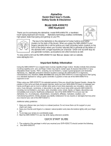
Connecting the Speakers
Center speaker
Red
White
Green
Gray Blue
Surround
left
speaker
Surround
right
speaker
Powered
subwoofer
Tan
Brown
(Height)
(Front)
Front & Height
right speaker
Front & Height
left speaker
HTP-588_En_SN29402011_1503xx.book 3 ページ 2015年3月12日 木曜日 午後2時56
En-4
Front & Height Speakers (SKF-594)
Center Speaker (SKC-594)
Surround Speakers (SKR-594)
Powered Subwoofer (SKW-658)
Specifications and appearance are subject to change
without prior notice.
Note
For non-magnetic shielded speakers:
Try moving the speakers away from your TV or monitor. If
discoloration should occur, turn off your TV or monitor,
wait 15 to 30 minutes, and then turn it back on again. This
normally activates the degaussing function, which
neutralizes the magnetic field, thereby removing any
discoloration effects.
SN 29402011
(C) Copyright 2015 Onkyo Corporation Japan. All rights reserved.
Specifications
Dimensions (W × H × D) 155 mm × 467 mm × 183 mm
6-1/8" × 18-3/8" × 7-3/16"
(incl. grille and projection)
Weight 3.6 kg (7.9 lbs.)
Keyhole slot Available
Grille Fixed
Front Unit
Type 2 Way Bass-Reflex
Impedance 6 Ω
Maximum input power 130 W
Sensitivity 83 dB/W/m
Frequency response 55 Hz to 50 kHz
Crossover frequency 4kHz
Cabinet capacity 5.7 L (0.20 cubic feet)
Drivers unit 12 cm (5") Cone Woofer × 1
2.5 cm (1") Balanced Dome × 1
Terminal Spring type color coded
Other Non-magnetic shielding
Height Unit
Type Full Range Closed Box
Impedance 6 Ω
Maximum input power 130 W
Sensitivity 81 dB/W/m
Frequency response 80 Hz to 20 kHz
Cabinet capacity 1.0 L (0.036 cubic feet)
Drivers unit 8 cm (3-1/4") Cone Speaker
Terminal Spring type color coded
Other Non-magnetic shielding
Type 2 Way Bass-Reflex
Impedance 6 Ω
Maximum input power 130 W
Sensitivity 86 dB/W/m
Frequency response 65 Hz to 50 kHz
Crossover frequency 6kHz
Cabinet capacity 2.8 L (0.10 cubic feet)
Dimensions (W × H × D) 409 mm × 115 mm × 121 mm
16-1/8" × 4-1/2" × 4-3/4"
(incl. grille and projection)
Weight 2.2 kg (4.9 lbs.)
Drivers unit 8 cm (3-1/4") Cone Woofer × 2
2.5 cm (1") Balanced Dome × 1
Terminal Spring type color coded
Keyhole slot Available
Grille Fixed
Other Non-magnetic shielding
Type Full Range Closed Box
Impedance 6 Ω
Maximum input power 130 W
Sensitivity 81 dB/W/m
Frequency response 80 Hz to 20 kHz
Cabinet capacity 1.0 L (0.036 cubic feet)
Dimensions (W × H × D) 115 mm × 230 mm × 96 mm
4-1/2" × 9-1/16" × 3-3/4"
(incl. grille and projection)
Weight 1.0 kg (2.2 lbs.)
Drivers unit 8 cm (3-1/4") Cone Speaker × 1
Terminal Spring type color coded
Keyhole slot Available
Grille Fixed
Other Non-magnetic shielding
Type Bass-Reflex
Input sensitivity/Impedance
440 mV/20 kΩ
Rated output Power (IEC)
80 watts minimum continuous power,
4 ohms, driven at 100 Hz with a
maximum total harmonic distortion of
1%
Frequency response 27 Hz to 150 Hz
Cabinet capacity 24.5 L (0.86 cubic feet)
Dimensions (W × H × D) 230 mm × 425 mm × 410 mm
9-1/16" × 16-3/4" × 16-1/8"
(incl. projection)
Weight 7.7 kg (17.0 lbs.)
Audio input 1 (RCA analog mono)
Drivers unit 20 cm (8") Cone Woofer × 1
Power supply AC 220 -240 V, 50/60 Hz
Power consumption 20 W
Other Auto Standby function
Non-magnetic shielding
HTP-588_En_SN29402011_1503xx.book 4 ページ 2015年3月12日 木曜日 午後2時56
  • Page 1 1
  • Page 2 2
  • Page 3 3
  • Page 4 4

ONKYO (HTP-588) Owner's manual

Category
Home audio sets
Type
Owner's manual
This manual is also suitable for

Ask a question and I''ll find the answer in the document

Finding information in a document is now easier with AI