Omega RS-232 User manual
- Category
- Toys & accessories
- Type
- User manual
This manual is also suitable for

www.omega.com
e-mail: [email protected]
User’s Guide
OMG-ULTRACOMM2-PCI
Dual Port PCI RS-232/422/485 Interface Board
Shop online at

Servicing North America:
USA: One Omega Drive, P.O. Box 4047
ISO 9001 Certified Stamford CT 06907-0047
TEL: (203) 359-1660 FAX: (203) 359-7700
e-mail: [email protected]
Canada: 976 Bergar
Laval (Quebec) H7L 5A1, Canada
TEL: (514) 856-6928 FAX: (514) 856-6886
e-mail: [email protected]
For immediate technical or application assistance:
USA and Canada: Sales Service: 1-800-826-6342 / 1-800-TC-OMEGA
®
Customer Service: 1-800-622-2378 / 1-800-622-BEST
®
Engineering Service: 1-800-872-9436 / 1-800-USA-WHEN
®
TELEX: 996404 EASYLINK: 62968934 CABLE: OMEGA
Mexico: En Espan˜ol: (001) 203-359-7803 e-mail: [email protected]
FAX: (001) 203-359-7807 [email protected]
Servicing Europe:
Benelux: Postbus 8034, 1180 LA Amstelveen, The Netherlands
TEL: +31 (0)20 3472121 FAX: +31 (0)20 6434643
Toll Free in Benelux: 0800 0993344
e-mail: [email protected]
Czech Republic: Frystatska 184, 733 01 Karviná, Czech Republic
TEL: +420 (0)59 6311899 FAX: +420 (0)59 6311114
Toll Free: 0800-1-66342 e-mail: [email protected]
France: 11, rue Jacques Cartier, 78280 Guyancourt, France
TEL: +33 (0)1 61 37 29 00 FAX: +33 (0)1 30 57 54 27
Toll Free in France: 0800 466 342
e-mail: [email protected]
Germany/Austria: Daimlerstrasse 26, D-75392 Deckenpfronn, Germany
TEL: +49 (0)7056 9398-0 FAX: +49 (0)7056 9398-29
Toll Free in Germany: 0800 639 7678
e-mail: [email protected]
United Kingdom: One Omega Drive, River Bend Technology Centre
ISO 9002 Certified Northbank, Irlam, Manchester
M44 5BD United Kingdom
TEL: +44 (0)161 777 6611 FAX: +44 (0)161 777 6622
Toll Free in United Kingdom: 0800-488-488
e-mail: [email protected]
OMEGAnet
®
Online Service Internet e-mail
www.omega.com [email protected]
It is the policy of OMEGA to comply with all worldwide safety and EMC/EMI regulations that
apply. OMEGA is constantly pursuing certification of its products to the European New Approach
Directives. OMEGA will add the CE mark to every appropriate device upon certification.
The information contained in this document is believed to be correct, but OMEGA Engineering, Inc. accepts
no liability for any errors it contains, and reserves the right to alter specifications without notice.
WARNING: These products are not designed for use in, and should not be used for, patient-connected applications.

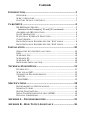
Contents
INTRODUCTION..........................................................................1
OVERVIEW................................................................................................1
WHAT’S INCLUDED................................................................................1
FACTORY DEFAULT SETTINGS............................................................1
CARD SETUP ..............................................................................2
RS-485 ENABLE MODES.........................................................................2
Interface Mode Examples J1B and J2B (continued).......................4
ADDRESS AND IRQ SELECTION............................................................4
LINE TERMINATION...............................................................................5
ELECTRICAL INTERFACE SELECTION.................................................6
CLOCK MODES........................................................................................7
BAUD RATES AND DIVISORS FOR THE ‘DIV1’ MODE ........................8
BAUD RATES AND DIVISORS FOR THE ‘DIV2’ MODE ........................9
INSTALLATION ........................................................................10
OPERATING SYSTEM INSTALLATION...............................................10
DOS.........................................................................................................10
WINDOWS 3.1X......................................................................................10
WINDOWS 95.........................................................................................10
WINDOWS NT........................................................................................10
HARDWARE INSTALLATION...............................................................10
TECHNICAL DESCRIPTION.......................................................11
INTERRUPTS..........................................................................................11
WHY USE AN ISP?.................................................................................12
CONNECTOR PIN ASSIGNMENTS........................................................12
RS-232..................................................................................................12
RS-422/485..........................................................................................13
SPECIFICATIONS ......................................................................14
ENVIRONMENTAL SPECIFICATIONS..................................................14
MANUFACTURING ...............................................................................14
POWER CONSUMPTION........................................................................14
MEAN TIME BETWEEN FAILURES (MTBF).....................................14
PHYSICAL DIMENSIONS........................................................................14
APPENDIX A - TROUBLESHOOTING.........................................15
APPENDIX B - HOW TO GET ASSISTANCE..............................16

APPENDIX C - ELECTRICAL INTERFACE...................................17
RS-232.....................................................................................................17
RS-422.....................................................................................................17
RS-485.....................................................................................................18
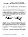
APPENDIX D - ASYNCHRONOUS COMMUNICATIONS ...............19
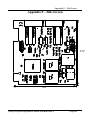
APPENDIX E - SILK-SCREEN ....................................................20
APPENDIX F - COMPLIANCE NOTICES .....................................21
FEDERAL COMMUNICATIONS COMMISSION STATEMENT............21
EMC DIRECTIVE STATEMENT...........................................................21
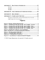
Figures
Figure 1- Headers J1B and J2B, RS-422..........................................................3
Figure 2 - Headers J1B and J2B, RS-485 ‘Auto’ Enabled, ‘No Echo’..........3
Figure 3 - Headers J1B and J2B, RS-485 ‘Auto’ Enabled, ‘Echo’................3
Figure 4 - Headers J1B and J2B, RS-485 ‘RTS’ Enabled, ‘No Echo’..........4
Figure 5 - Headers J1B and J2B, RS-485 ‘RTS’ Enabled, ‘Echo’................4
Figure 6 - Headers J1A and J2A, Line Termination.......................................5
Figure 7 Headers E1 - E4, Electrical Interface Selection...............................6
Figure 8 - Clocking Mode 'Divide By 4’............................................................7
Figure 9 - Clocking Mode 'Divide By 2’............................................................7
Figure 10 - Clocking Mode 'Divide By 1’..........................................................7
Figure 11 - Asynchronous Communications Bit Diagram..........................19
© 1998f Omega Engineering, Incorporated. All rights reserved.

Introduction
Omega Engineering OMG-ULTRA COMM+2.PCI Page 1
Introduction
Overview
The OMG-ULTRA COMM+2.PCI is a two channel PCI Bus serial I/O adapter for
the PC and compatibles. It provides two field selectable RS-232/422/485 serial
ports supporting data rates up to 460.8K bps.
Configure both ports as RS-232 for standard serial COM: port requirements.
Choose the RS-422 mode for long distance device connections up to 4000ft.
where noise immunity and high data integrity are essential. Select RS-485 and
capture data from multiple peripherals in a RS-485 multidrop network. Up to 31
RS-485 devices can be connected to each port to automate your data collection.
You can even mix the ports in any of the interface combinations to provide
maximum flexibility to your application.
In both RS-232 and RS-422 modes, the card works seamlessly with the standard
operating system serial driver. In RS-485 mode, our special auto-enable feature
allows the RS-485 ports to be viewed by the operating system as a COM: port.
This allows the standard COM: driver to be utilized for RS-485 communications.
Our on-board hardware automatically handles the RS-485 driver enable. UART
upgrades are available providing 32 and 64 byte FIFOs.
What’s Included
The OMG-ULTRA COMM+2.PCI is shipped with the following items. If any of
these items are missing or damaged, contact the supplier.
• OMG-ULTRA COMM+2.PCI Serial I/O Adapter
• Serial Utility Software
• User Manual
Factory Default Settings
The OMG-ULTRA COMM+2.PCI factory default settings are as follows:
Port # Electrical Specification
Port 1 RS-232
Port 2 RS-232
To install the OMG-ULTRA COMM+2.PCI using factory default settings, refer
to Installation on page 10.
For your reference, record installed OMG-ULTRA COMM+2.PCI settings below:
Port # Electrical Specification
Port 1
Port 2

Card Setup
Omega Engineering OMG-ULTRA COMM+2.PCI Page 2
Card Setup
In all cases J1x refers to settings for the first port and J2x refer to settings for
the second port.
RS-485 Enable Modes
RS-485 is ideal for multi-drop or network environments. RS-485 requires a tri-state
driver that will allow the electrical presence of the driver to be removed from the
line. The driver is in a tri-state or high impedance condition when this occurs.
Only one driver may be active at a time and the other driver(s) must be tri-stated.
The output modem control signal Request To Send (RTS) is typically used to
control the state of the driver. Some communication software packages refer to
RS-485 as RTS enable or RTS block mode transfer.
One of the unique features of the OMG-ULTRA COMM+2.PCI is the ability to
be RS-485 compatible without the need for special software or drivers. This
ability is especially useful in Windows, Windows NT, and OS/2 environments
where the lower level I/O control is abstracted from the application program. This
ability means that the user can effectively use the OMG-ULTRA COMM+2.PCI
in a RS-485 application with existing (i.e. standard RS-232) software drivers.
Headers J1B and J2B are used to control the RS-485 mode functions for the driver
circuit. The selections are ‘RTS’ enable (silk-screen ‘RT’) or ‘Auto’ enable (silk-
screen ‘AT’). The ‘Auto’ enable feature automatically enables/disables the
RS-485 interface. The ‘RTS’ mode uses the ‘RTS’ modem control signal to
enable the RS-485 interface and provides backward compatibility with existing
software products.
Position 3 (silk-screen ‘NE’) of J1B and J2B is used to control the RS-485
enable/disable functions for the receiver circuit and determine the state of the
RS-422/485 driver. The RS-485 ‘Echo’ is the result of connecting the receiver
inputs to the transmitter outputs. Every time a character is transmitted; it is also
received. This can be beneficial if the software can handle echoing (i.e. using
received characters to throttle the transmitter) or it can confuse the system if the
software does not. To select the ‘No Echo’ mode select silk-screen position ‘NE’.
For RS-422/530/449 compatibility remove the jumpers at J1B and J2B.
Examples on the following pages describe all of the valid settings for J1B and
J2B.

Card Setup
Omega Engineering OMG-ULTRA COMM+2.PCI Page 3
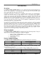
Interface Mode Examples J1D – J4D
AT
RT
NE
Figure 1- Headers J1B and J2B, RS-422
AT
RT
NE
Figure 2 - Headers J1B and J2B, RS-485 ‘Auto’ Enabled, with ‘No Echo’
AT
RT
NE
Figure 3 - Headers J1B and J2B, RS-485 ‘Auto’ Enabled, with ‘Echo’

Card Setup
Omega Engineering OMG-ULTRA COMM+2.PCI Page 4
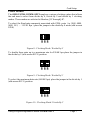
Interface Mode Examples J1B and J2B (continued)
AT
RT
NE
Figure 4 - Headers J1B and J2B, RS-485 ‘RTS’ Enabled, with ‘No Echo’
AT
RT
NE
Figure 5 - Headers J1B and J2B, RS-485 ‘RTS’ Enabled, with ‘Echo’
Address and IRQ selection
The OMG-ULTRA COMM+2.PCI is automatically assigned I/O addresses and
IRQs by your motherboard BIOS. Only the I/O address may be modified by the
user.
Adding or removing other hardware may change the assignment of I/O
addresses and IRQs.

Card Setup
Omega Engineering OMG-ULTRA COMM+2.PCI Page 5
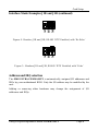
Line Termination
Typically, each end of the RS-485 bus must have line terminating resistors
(RS-422 terminates at the receive end only). A 120-ohm resistor is across each
RS-530/422/485 input in addition to a 1K ohm pull-up/pull-down combination that
biases the receiver inputs. Headers J1A and J2A allow the user to customize this
interface to their specific requirements. Each jumper position corresponds to a
specific portion of the interface. If multiple OMG-ULTRA COMM+2.PCI
adapters are configured in a RS-485 network, only the boards on each end should
have jumpers T, P & P ON. Refer to the following table for each position’s
operation:
Name Function
P Adds or removes the 1K ohm pull-down resistor in the
RS-422/RS-485 receiver circuit (Receive data only).
P Adds or removes the 1K ohm pull-up resistor in the RS-422/RS-
485 receiver circuit (Receive data only).
T Adds or removes the 120 ohm termination.
L Connects the TX+ to RX+ for RS-485 two wire operation.
L Connects the TX- to RX- for RS-485 two wire operation.
P P T L L
Figure 6 - Headers J1A and J2A, Line Termination

Card Setup
Omega Engineering OMG-ULTRA COMM+2.PCI Page 6
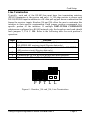
Electrical Interface Selection
Each port on the OMG-ULTRA COMM+2.PCI has the ability to be used in either
RS-232 or RS-422/485. This is selectable via four 24 pin DIP-shunts at E1-E4.
Please use the following illustration to aid in the configuration of your electrical
interface.
E1
E2
Port 1
RS-232RS-422
E3
E4
Port 2
RS-232RS-422
RS-232
E1
E2
Port 1
RS-232RS-422
E3
E4
Port 2
RS-232RS-422
RS-422/485
RS-232 and RS-422/485
E1
E2
Port 1
RS-232RS-422
E3
E4
Port 2
RS-232RS-422
Figure 7 Headers E1 - E4, Electrical Interface Selection

Card Setup
Omega Engineering OMG-ULTRA COMM+2.PCI Page 7
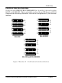
Clock Modes
The OMG-ULTRA COMM+2.PCI employs a unique clocking option that allows
the end user to select from divide by 4, divide by 2 and divide by 1 clocking
modes. These modes are selected at Headers J1C through J4C.
To select the Baud rates commonly associated with COM: ports (i.e. 2400, 4800,
9600, 19.2, … 115.2K Bps ) place the jumper in the divide by 4 mode (silk-screen
DIV4).
DIV1
DIV2
DIV4
Figure 8 - Clocking Mode 'Divide By 4’
To double these rates up to a maximum rate for 230.4K bps place the jumper in
the divide by 2 (silk-screen DIV2) position.
DIV1
DIV2
DIV4
Figure 9 - Clocking Mode 'Divide By 2’
To select the maximum data rate (460.8K bps) place the jumper in the divide by 1
(silk-screen DIV1) position.
DIV1
DIV2
DIV4
Figure 10 - Clocking Mode 'Divide By 1’

Card Setup
Omega Engineering OMG-ULTRA COMM+2.PCI Page 8
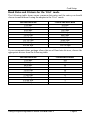
Baud Rates and Divisors for the ‘Div1’ mode
The following table shows some common data rates and the rates you should
choose to match them if using the adapter in the ‘Div1’ mode.
For this Data Rate Choose this Data Rate
1200 bps 300 bps
2400 bps 600 bps
4800 bps 1200 bps
9600 bps 2400 bps
19.2K bps 4800 bps
57.6 K bps 14.4K bps
115.2 K bps 28.8K bps
230.4K bps 57.6 K bps
460.8K bps 115.2 K bps
If your communications package allows the use of Baud rate divisors, choose the
appropriate divisor from the following table:
For this Data Rate Choose this Divisor
1200 bps 384
2400 bps 192
4800 bps 96
9600 bps 48
19.2K bps 24
38.4K bps 12
57.6K bps 8
115.2K bps 4
230.4K bps 2
460.8K bps 1

Card Setup
Omega Engineering OMG-ULTRA COMM+2.PCI Page 9
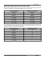
Baud Rates and Divisors for the ‘Div2’ mode
The following table shows some common data rates and the rates you should
choose to match them if using the adapter in the ‘Div2’ mode.
For this Data Rate Choose this Data Rate
1200 bps 600 bps
2400 bps 1200 bps
4800 bps 2400bps
9600 bps 4800 bps
19.2K bps 9600 bps
38.4K bps 19.2K bps
57.6 K bps 28.8K bps
115.2 K bps 57.6 K bps
230.4 K bps 115.2 K bps
If your communications package allows the use of Baud rate divisors, choose the
appropriate divisor from the following table:
For this Data Rate Choose this Divisor
1200 bps 192
2400 bps 96
4800 bps 48
9600 bps 24
19.2K bps 12
38.4K bps 8
57.6K bps 4
115.2K bps 2
230.4K bps 1

Installation
Omega Engineering OMG-ULTRA COMM+2.PCI Page 10
Installation
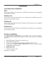
Operating System Installation
DOS
Refer to the ‘PCI.txt’ file found in the \DOS\PCI sub-directory on the supplied
Serial Utilities Diskette.
Windows 3.1x
Refer to the Win3x.hlp file found in the \Windows\3.1x sub-directory on the
supplied Serial Utilities Diskette.
Windows 95
Refer to the PCI.hlp file found in the \Windows\95 sub-directory on the supplied
Serial Utilities Diskette.
Windows NT
Refer to the PCI.hlp file found in the \Windows\NT sub-directory on the supplied
Serial Utilities Diskette.
Hardware Installation
The OMG-ULTRA COMM+2.PCI can be installed in any of the PCI expansion
slots and contains several jumper straps for each port that must be set for proper
operation.
1. Turn off PC power. Disconnect the power cord.
2. Remove the PC case cover.
3. Locate an available PCI slot and remove the blank metal slot cover.
4. Gently insert the OMG-ULTRA COMM+2.PCI into the slot. Make sure that
the adapter is seated properly.
5. Replace the screw.
6. Replace the cover.
7. Connect the power cord.
Installation is complete.

Technical Description
Omega Engineering OMG-ULTRA COMM+2.PCI Page 11
Technical Description
The Omega Engineering OMG-ULTRA COMM+2.PCI provides a PCI interface
adapter with 2 asynchronous serial ports providing a versatile interface, field
selectable as RS-232 for modems, printers and plotters, as well as RS-422/485 for
industrial automation and control applications.
The OMG-ULTRA COMM+2.PCI utilizes the 16550 UART. This chip features
programmable baud rates, data format, interrupt control and a 16-byte input and
output FIFO. Also available as an option is the 16C650 UART that provides a
deeper FIFO (32 bytes) and enhanced clocking features.
Interrupts
A good description of an interrupt and it’s importance to the IBM PC can be
found in the book ‘Peter Norton’s Inside the PC, Premier Edition’:
“ One of the key things that makes a computer different from any other kind of
man-made machine is that computers have the capability to respond to the
unpredictable variety of work that comes to them. The key to this capability is a
feature known as interrupts. The interrupt feature enables the computer to
suspend whatever it is doing and switch to something else in response to an
interruption, such as the press of a key on the keyboard.”
A good analogy of a PC interrupt would be the phone ringing. The phone ‘bell’
is a request for us to stop what we are currently doing and take up another task
(speak to the person on the other end of the line). This is the same process the
PC uses to alert the CPU that a task must be preformed. The CPU upon receiving
an interrupt makes a record of what the processor was doing at the time and
stores this information on the ‘stack’; this allows the processor to resume its
predefined duties after the interrupt is handled, exactly where it left off. Every
main sub-system in the PC has it’s own interrupt, frequently called an IRQ (short
for Interrupt ReQuest). The following IRQ table will define the system IRQs as
well as show typically free IRQs.
In these early days of PC’s Omega Engineering decided that the ability to share
IRQs was an important feature for any add-in I/O card. Consider that in the IBM
XT the available IRQs were IRQ0 through IRQ7. Of these interrupts only IRQ2-5
and IRQ7 were actually available for use. This made the IRQ a very valuable
system resource. To make the maximum use of these system resources Omega
Engineering devised an IRQ sharing circuit that allowed more than one port to
use a selected IRQ. This worked fine as a hardware solution but presented the

Technical Description
Omega Engineering OMG-ULTRA COMM+2.PCI Page 12
software designer with a challenge to identify the source of the interrupt. The
software designer frequently used a technique referred to as ‘round robin
polling’. This method required the interrupt service routine to ‘poll’ or interrogate
each UART as to its interrupt pending status. This method of polling was
sufficient for use with slower speed communications, but as modems increased
their through put abilities this method of servicing shared IRQs became
inefficient.
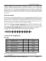
Why use an ISP?
The answer to the polling inefficiency was the Interrupt Status Port (ISP). The
ISP is a read only 8-bit register that sets a corresponding bit when an interrupt is
pending. Port 1 interrupt line corresponds with Bit D0 of the status port, Port 2
with D1 etc. The use of this port means that the software designer now only has
to poll a single port to determine if an interrupt is pending.
The ISP is at Base+7 on each port (Example: Base = 280 Hex, Status Port = 287,
28F… etc.). The OMG-ULTRA COMM+2.PCI will allow any one of the available
locations to be read to obtain the value in the status register. Both status ports
on the OMG-ULTRA COMM+2.PCI are identical, so any one can be read.
Example: This indicates that Channel 2 has an interrupt pending.
Bit Position: 7 6 5 4 3 2 1 0
Value Read: 0 0 0 0 0 0 1 0
Connector Pin Assignments
RS-232
Name Pin # Mode
TD Transmit Data 3 Output
RTS Request To Send 7 Output
DTR Data Term Ready 4 Output
GND Ground 5
RD Receive Data 2 Input
DCD Data Carrier Detect 1 Input
DSR Data Set Ready 6 Input
CTS Clear To Send 8 Input
RI Ring Indicator 9 Input
Note: These assignments meet EIA/TIA/ANSI-574 DTE for DB-9 type
connectors.

Technical Description
Omega Engineering OMG-ULTRA COMM+2.PCI Page 13
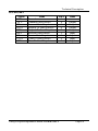
RS-422/485
Signal Name Pin # Mode
GND Ground 5
TX + Transmit Data Positive 4 Output
TX- Transmit Data Negative 3 Output
RTS+ Request To Send Positive 6 Output
RTS- Request To Send Negative 7 Output
RX+ Receive Data Positive 1 Input
RX- Receive Data Negative 2 Input
CTS+ Clear To Send Positive 9 Input
CTS- Clear To Send Negative 8 Input

Specifications
Omega Engineering OMG-ULTRA COMM+2.PCI Page 14
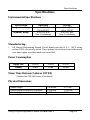
Specifications
Environmental Specifications
Specification Operating Storage
Temperature Range
0º to 50º C
(32º to 122º F)
-20º to 70º C
(-4º to 158º F)
Humidity Range 10 to 90% R.H.
Non-Condensing
10 to 90% R.H.
Non-Condensing
Manufacturing .
• All Omega Engineering Printed Circuit boards are built to U. L. 94V0 rating
and are 100% electrically tested. These printed circuit boards are solder mask
over bare copper or solder mask over tin nickel.
Power Consumption
Supply line +12VDC -12VDC +5 VDC
Rating 50 mA 50 mA 480 mA
Mean Time Between Failures (MTBF)
Greater than 150,000 hours. (Calculated)
Physical Dimensions
Board length 5.0 inches (12.7 cm)
Board Height including Goldfingers 4.2 inches (10.66 cm)
Board Height excluding Goldfingers 3.875 inches (9.841 cm)

Appendix A - Troubleshooting
Omega Engineering OMG-ULTRA COMM+2.PCI Page 15
Appendix A - Troubleshooting
A Serial Utility Diskette is supplied with the Omega Engineering adapter and will
be used in the troubleshooting procedures. By using this diskette and following
these simple steps, most common problems can be eliminated without the need to
call Technical Support.
1. Identify all I/O adapters currently installed in your system. This includes
your on-board serial ports, controller cards, sound cards etc. The I/O
addresses used by these adapters, as well as the IRQ (if any) should be
identified.
2. Configure your Omega Engineering adapter so that there is no conflict with
currently installed adapters. No two adapters can occupy the same I/O
address.
3. Make sure the Omega Engineering adapter is using a unique IRQ. While the
Omega Engineering adapter does allow the sharing of IRQs, many other
adapters (i.e. SCSI adapters & on-board serial ports) do not. The IRQ is
typically selected via an on-board header block. Refer to the section on Card
Setup for help in choosing an I/O address and IRQ.
4. Make sure the Omega Engineering adapter is securely installed in a
motherboard slot.
5. When running DOS, Windows 3.x or other operating systems refer to the
Serial Utilities Disk 1 and the User Manual to verify that the Omega
Engineering adapter is configured correctly. The supplied software contains
a diagnostic program 'SSD' that runs under DOS and will verify if an adapter
is configured properly. This diagnostic program is written with the user in
mind and is easy to use. Refer to the README.txt file on the supplied
diskette for detailed instructions on using 'SSD'.
6. For Windows 95/98 and Windows NT, the diagnostic tool 'WinSSD' is
installed in the Omega folder on the Start Menu during the setup process.
First find the ports using the Device Manager, then use 'WinSSD' to verify
that the ports are functional.
Always use the Omega Engineering diagnostic software when troubleshooting a
problem. This will help eliminate any software issues and identify any hardware
conflicts

Appendix B - How To Get Assistance
Omega Engineering OMG-ULTRA COMM+2.PCI Page 16
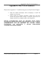
Appendix B - How To Get Assistance
Please refer to Appendix A - Troubleshooting prior to calling Technical Support.
1. Read this manual thoroughly before attempting to install the
adapter in your system.
2. When calling for technical assistance, please have your user
manual and current adapter settings. If possible, please have the
adapter installed in a computer ready to run diagnostics.
RETURN AUTHORIZATION MUST BE OBTAINED FROM OMEGA
ENGINEERING BEFORE RETURNED MERCHANDISE WILL BE ACCEPTED.
AUTHORIZATION CAN BE OBTAINED BY CALLING OMEGA
ENGINEERING AND REQUESTING A RETURN MERCHANDISE
AUTHORIZATION (RMA) NUMBER.
Page is loading ...
Page is loading ...
Page is loading ...
Page is loading ...
Page is loading ...
Page is loading ...
Page is loading ...
-
 1
1
-
 2
2
-
 3
3
-
 4
4
-
 5
5
-
 6
6
-
 7
7
-
 8
8
-
 9
9
-
 10
10
-
 11
11
-
 12
12
-
 13
13
-
 14
14
-
 15
15
-
 16
16
-
 17
17
-
 18
18
-
 19
19
-
 20
20
-
 21
21
-
 22
22
-
 23
23
-
 24
24
-
 25
25
-
 26
26
-
 27
27


Omega RS-232 User manual
- Category
- Toys & accessories
- Type
- User manual
- This manual is also suitable for
Ask a question and I''ll find the answer in the document
Finding information in a document is now easier with AI
Related papers
-
Omega OMG-VERSACOMM4-PCI Owner's manual
-
-
-
-
Omega Engineering OMG-USB-232-4 User manual
-
-
-
Omega Engineering OMG-ULTRACOMM422 User manual
-
-
Other documents
-
Longshine LCS-6024P Datasheet
-
SeaLevel Ultra COMM+2.PCI User manual
-
-
-
-
-
Lava Computer 16550 UARTs User manual
-
Quatech DS-1000 Owner's manual
-
-