Manual No. 0-2023
Instruction Manual
WELD SEQUENCER
December 16, 2005
A-02401


Read and understand this entire Manual and your employer’s
safety practices before installing, operating, or servicing the
equipment.
While the information contained in this manual represents our
best judgement, Thermal Arc Corporation assumes no liability
for its use.
Thermal Arc
®
Weld Sequencer
Instruction Manual Number 0-2023
Published by:
Thermal Dynamics Corporation
Industrial Park No. 2
West Lebanon, New Hampshire, USA 03784
(603) 298-5711
Copyright 1984
Thermal Dynamics Corporation
All rights reserved.
Reproduction of this work, in whole or in part, without written
permission of the publisher is prohibited.
The publisher does not assume and hereby disclaims any liabil-
ity to any party for any loss or damage caused by any error or
omission in the Thermal Arc
®
Weld Sequencer Instruction
Manual, whether such error results from negligence, accident, or
any other cause.
Revised on December 16, 2005
WARNING
WARNING

TABLE OF CONTENTS
SECTION 1:
GENERAL INFORMATION ................................................................................................... 1
1.01 Notes, Cautions and Warnings ........................................................................ 1
1.02 Important Safety Precautions ........................................................................ 1
1.03 Publications ................................................................................................... 2
1.04 Note, Attention et Avertissement ................................................................... 3
1.05 Precautions De Securite Importantes............................................................. 3
1.06 Documents De Reference .............................................................................. 5
1.07 Declaration of Conformity ............................................................................... 6
1.08 Statement of Warranty .................................................................................... 7
SECTION 2:
INTRODUCTION & DESCRIPTION ...................................................................................... 9
2.01 Scope of Manual ............................................................................................ 9
2.02 General Description ........................................................................................ 9
2.03 Specifications & Design Features .................................................................10
SECTION 3:
INSTALLATION PROCEDURES .......................................................................................... 11
3.01 Introduction ................................................................................................... 11
3.02 Site Selection ...............................................................................................11
3.03 Unpacking .....................................................................................................11
3.04 Equipment Installation - General ................................................................... 11
3.05 WT1 Weld Timer ............................................................................................13
3.06 GS1 Gas Slope .............................................................................................15
3.07 CS1 Current Slope ........................................................................................ 17
3.08 CP1 Pulser ................................................................................................... 17
3.09 Automatic Voltage Control (AVC) Lockout .....................................................17
3.10 Auxiliary Connections For Interfacing External Controls ................................ 17
SECTION 4:
OPERATION ........................................................................................................................19
4.01 Introduction ................................................................................................... 19
4.02 Functional Overview .................................................................................... 19
4.03 Weld Sequencer Enclosure Control Descriptions ..........................................19
4.04 RP1 Control Descriptions ..............................................................................20
4.05 WT1 Weld Timer Control Descriptions............................................................ 20
4.06 CS1 Current Slope Control Descriptions ........................................................21
4.07 CP1 Pulser Control Descriptions ...................................................................22
4.08 GS1 Gas Slope Control Descriptions ............................................................23
4.09 Pre-Operation Setup...................................................................................... 24
4.10 System Operation .........................................................................................27

TABLE OF CONTENTS (continued)
SECTION 5:
CUSTOMER/OPERATOR SERVICE .................................................................................... 29
5.01 Introduction ...................................................................................................29
5.02 Transformer Connections ...............................................................................29
5.03 Troubleshooting Guide - General Information ................................................. 29
5.04 Test Procedures ............................................................................................33
5.05 WT1 Weld Timer Parts Replacement Procedures .......................................... 34
SECTION 6:
PARTS LIST ........................................................................................................................39
6.01 Introduction ...................................................................................................39
6.02 Ordering Information......................................................................................39
6.03 Weld Sequencer Enclosure ........................................................................... 40
6.04 GS1 Gas Slope (Front Panel) ........................................................................42
6.05 GS1 Gas Slope (Rear Panel) .........................................................................43
6.06 CS1 Current Slope ........................................................................................ 44
6.07 CP1 Pulser ...................................................................................................45
6.08 WT1 Weld Timer ............................................................................................46
6.09 RP1 Remote Pendant Control ........................................................................47
APPENDIX I: MOTION CONTROL & WIRE FEED INTERFACE DIAGRAM ................................49
APPENDIX II: WELD SEQUENCER TERMINAL STRIP DIAGRAM ............................................50
APPENDIX III: AUXILIARY INTERFACE CONNECTION DIAGRAM ...........................................51
APPENDIX IV: NECESSARY CONNECTIONS - RP-1 NOT USED WITH CS-1 WITH OR WITHOUT GS-1,
WT-1 OR CP-1 ..................................................................................................................... 52
APPENDIX V: NECESSARY CONNECTIONS - RP-1 NOT USED WITH CP-1, WT-1 SYSTEM ... 53
APPENDIX VI: TIMING AND SEQUENCE OF OPERATION FOR WELD SEQUENCER (ALL MODELS)
54
APPENDIX VII: TIMING AND SEQUENCE OF OPERATION FOR GS1 GAS SLOPE ONLY ......55
APPENDIX VIII: SYSTEM SCHEMATIC .....................................................................................56


Special TA 2/25/99 1 GENERAL INFORMATION
SECTION 1:
GENERAL INFORMATION
1.01 Notes, Cautions and Warnings
Throughout this manual, notes, cautions, and warnings
are used to highlight important information. These high-
lights are categorized as follows:
NOTE
An operation, procedure, or background informa-
tion which requires additional emphasis or is help-
ful in efficient operation of the system.
CAUTION
A procedure which, if not properly followed, may
cause damage to the equipment.
WARNING
A procedure which, if not properly followed, may
cause injury to the operator or others in the oper-
ating area.
1.02 Important Safety Precautions
WARNING
OPERATION AND MAINTENANCE OF
PLASMA ARC EQUIPMENT CAN BE DAN-
GEROUS AND HAZARDOUS TO YOUR
HEALTH.
To prevent possible injury, read, understand and
follow all warnings, safety precautions and in-
structions before using the equipment. Call 1-603-
298-5711 or your local distributor if you have any
questions.
GASES AND FUMES
Gases and fumes produced during the plasma cutting
process can be dangerous and hazardous to your health.
• Keep all fumes and gases from the breathing area.
Keep your head out of the welding fume plume.
• Use an air-supplied respirator if ventilation is not
adequate to remove all fumes and gases.
• The kinds of fumes and gases from the plasma arc
depend on the kind of metal being used, coatings
on the metal, and the different processes. You must
be very careful when cutting or welding any met-
als which may contain one or more of the follow-
ing:
Antimony Chromium Mercury
Arsenic Cobalt Nickel
Barium Copper Selenium
Beryllium Lead Silver
Cadmium Manganese Vanadium
• Always read the Material Safety Data Sheets (MSDS)
that should be supplied with the material you are
using. These MSDSs will give you the information
regarding the kind and amount of fumes and gases
that may be dangerous to your health.
• For information on how to test for fumes and gases
in your workplace, refer to item 1 in Subsection
1.03, Publications in this manual.
• Use special equipment, such as water or down draft
cutting tables, to capture fumes and gases.
• Do not use the plasma torch in an area where com-
bustible or explosive gases or materials are located.
• Phosgene, a toxic gas, is generated from the vapors
of chlorinated solvents and cleansers. Remove all
sources of these vapors.
ELECTRIC SHOCK
Electric Shock can injure or kill. The plasma arc process
uses and produces high voltage electrical energy. This
electric energy can cause severe or fatal shock to the op-
erator or others in the workplace.
• Never touch any parts that are electrically “live” or
“hot.”
• Wear dry gloves and clothing. Insulate yourself from
the work piece or other parts of the welding cir-
cuit.
• Repair or replace all worn or damaged parts.
• Extra care must be taken when the workplace is
moist or damp.
• Install and maintain equipment according to NEC
code, refer to item 9 in Subsection 1.03, Publica-
tions.
• Disconnect power source before performing any ser-
vice or repairs.
• Read and follow all the instructions in the Operat-
ing Manual.

GENERAL INFORMATION 2 Special TA 2/25/99
FIRE AND EXPLOSION
Fire and explosion can be caused by hot slag, sparks, or
the plasma arc.
• Be sure there is no combustible or flammable mate-
rial in the workplace. Any material that cannot be
removed must be protected.
• Ventilate all flammable or explosive vapors from
the workplace.
• Do not cut or weld on containers that may have held
combustibles.
• Provide a fire watch when working in an area where
fire hazards may exist.
• Hydrogen gas may be formed and trapped under
aluminum workpieces when they are cut under-
water or while using a water table. DO NOT cut
aluminum alloys underwater or on a water table
unless the hydrogen gas can be eliminated or dis-
sipated. Trapped hydrogen gas that is ignited will
cause an explosion.
NOISE
Noise can cause permanent hearing loss. Plasma arc pro-
cesses can cause noise levels to exceed safe limits. You
must protect your ears from loud noise to prevent per-
manent loss of hearing.
• To protect your hearing from loud noise, wear pro-
tective ear plugs and/or ear muffs. Protect others
in the workplace.
• Noise levels should be measured to be sure the deci-
bels (sound) do not exceed safe levels.
• For information on how to test for noise, see item 1
in Subsection 1.03, Publications, in this manual.
PLASMA ARC RAYS
Plasma Arc Rays can injure your eyes and burn your skin.
The plasma arc process produces very bright ultra violet
and infra red light. These arc rays will damage your
eyes and burn your skin if you are not properly protected.
• To protect your eyes, always wear a welding hel-
met or shield. Also always wear safety glasses with
side shields, goggles or other protective eye wear.
• Wear welding gloves and suitable clothing to pro-
tect your skin from the arc rays and sparks.
• Keep helmet and safety glasses in good condition.
Replace lenses when cracked, chipped or dirty.
• Protect others in the work area from the arc rays.
Use protective booths, screens or shields.
• Use the shade of lens as suggested in the following
per ANSI/ASC Z49.1:
Minimum Protective Suggested
Arc Current Shade No. Shade No.
Less Than 300* 8 9
300 - 400* 9 12
400 - 800* 10 14
* These values apply where the actual arc is clearly
seen. Experience has shown that lighter filters
may be used when the arc is hidden by the work-
piece.
1.03 Publications
Refer to the following standards or their latest revisions
for more information:
1. OSHA, SAFETY AND HEALTH STANDARDS,
29CFR 1910, obtainable from the Superintendent of
Documents, U.S. Government Printing Office, Wash-
ington, D.C. 20402
2. ANSI Standard Z49.1, SAFETY IN WELDING AND
CUTTING, obtainable from the American Welding
Society, 550 N.W. LeJeune Rd, Miami, FL 33126
3. NIOSH, SAFETY AND HEALTH IN ARC WELD-
ING AND GAS WELDING AND CUTTING, obtain-
able from the Superintendent of Documents, U.S.
Government Printing Office, Washington, D.C. 20402
4. ANSI Standard Z87.1, SAFE PRACTICES FOR OC-
CUPATION AND EDUCATIONAL EYE AND FACE
PROTECTION, obtainable from American National
Standards Institute, 1430 Broadway, New York, NY
10018
5. ANSI Standard Z41.1, STANDARD FOR MEN’S
SAFETY-TOE FOOTWEAR, obtainable from the
American National Standards Institute, 1430 Broad-
way, New York, NY 10018
6. ANSI Standard Z49.2, FIRE PREVENTION IN THE
USE OF CUTTING AND WELDING PROCESSES,
obtainable from American National Standards Insti-
tute, 1430 Broadway, New York, NY 10018
7. AWS Standard A6.0, WELDING AND CUTTING
CONTAINERS WHICH HAVE HELD COMBUS-
TIBLES, obtainable from American Welding Society,
550 N.W. LeJeune Rd, Miami, FL 33126
8. NFPA Standard 51, OXYGEN-FUEL GAS SYSTEMS
FOR WELDING, CUTTING AND ALLIED PRO-
CESSES, obtainable from the National Fire Protec-
tion Association, Batterymarch Park, Quincy, MA
02269
9. NFPA Standard 70, NATIONAL ELECTRICAL
CODE, obtainable from the National Fire Protection
Association, Batterymarch Park, Quincy, MA 02269

Special TA 2/25/99 3 GENERAL INFORMATION
10. NFPA Standard 51B, CUTTING AND WELDING
PROCESSES, obtainable from the National Fire Pro-
tection Association, Batterymarch Park, Quincy, MA
02269
11. CGA Pamphlet P-1, SAFE HANDLING OF COM-
PRESSED GASES IN CYLINDERS, obtainable from
the Compressed Gas Association, 1235 Jefferson
Davis Highway, Suite 501, Arlington, VA 22202
12. CSA Standard W117.2, CODE FOR SAFETY IN
WELDING AND CUTTING, obtainable from the Ca-
nadian Standards Association, Standards Sales, 178
Rexdale Boulevard, Rexdale, Ontario, Canada M9W
1R3
13. NWSA booklet, WELDING SAFETY BIBLIOGRA-
PHY obtainable from the National Welding Supply
Association, 1900 Arch Street, Philadelphia, PA 19103
14. American Welding Society Standard AWSF4.1, REC-
OMMENDED SAFE PRACTICES FOR THE PREPA-
RATION FOR WELDING AND CUTTING OF CON-
TAINERS AND PIPING THAT HAVE HELD
HAZARDOUS SUBSTANCES, obtainable from the
American Welding Society, 550 N.W. LeJeune Rd,
Miami, FL 33126
15. ANSI Standard Z88.2, PRACTICE FOR RESPIRA-
TORY PROTECTION, obtainable from American
National Standards Institute, 1430 Broadway, New
York, NY 10018
1.04 Note, Attention et
Avertissement
Dans ce manuel, les mots “note,” “attention,” et
“avertissement” sont utilisés pour mettre en relief des
informations à caractère important. Ces mises en relief
sont classifiées comme suit :
NOTE
Toute opération, procédure ou renseignement
général sur lequel il importe d’insister davantage
ou qui contribue à l’efficacité de fonctionnement
du système.
ATTENTION
Toute procédure pouvant résulter
l’endommagement du matériel en cas de non-
respect de la procédure en question.
AVERTISSEMENT
Toute procédure pouvant provoquer des blessures
de l’opérateur ou des autres personnes se trouvant
dans la zone de travail en cas de non-respect de la
procédure en question.
1.05 Precautions De Securite
Importantes
AVERTISSEMENT
L’OPÉRATION ET LA MAINTENANCE DU
MATÉRIEL DE SOUDAGE À L’ARC AU JET
DE PLASMA PEUVENT PRÉSENTER DES
RISQUES ET DES DANGERS DE SANTÉ.
Il faut communiquer aux opérateurs et au person-
nel TOUS les dangers possibles. Afin d’éviter les
blessures possibles, lisez, comprenez et suivez tous
les avertissements, toutes les précautions de
sécurité et toutes les consignes avant d’utiliser le
matériel. Composez le + 603-298-5711 ou votre
distributeur local si vous avez des questions.
FUMÉE et GAZ
La fumée et les gaz produits par le procédé de jet de
plasma peuvent présenter des risques et des dangers de
santé.
• Eloignez toute fumée et gaz de votre zone de respi-
ration. Gardez votre tête hors de la plume de fumée
provenant du chalumeau.
• Utilisez un appareil respiratoire à alimentation en
air si l’aération fournie ne permet pas d’éliminer la
fumée et les gaz.
• Les sortes de gaz et de fumée provenant de l’arc de
plasma dépendent du genre de métal utilisé, des
revêtements se trouvant sur le métal et des différents
procédés. Vous devez prendre soin lorsque vous
coupez ou soudez tout métal pouvant contenir un
ou plusieurs des éléments suivants:
antimoine cadmium mercure
argent chrome nickel
arsenic cobalt plomb
baryum cuivre sélénium
béryllium manganèse vanadium
• Lisez toujours les fiches de données sur la sécurité
des matières (sigle américain “MSDS”); celles-ci
devraient être fournies avec le matériel que vous
utilisez. Les MSDS contiennent des renseignements
quant à la quantité et la nature de la fumée et des
gaz pouvant poser des dangers de santé.
• Pour des informations sur la manière de tester la
fumée et les gaz de votre lieu de travail, consultez
l’article 1 et les documents cités à la page 5.

GENERAL INFORMATION 4 Special TA 2/25/99
• Utilisez un équipement spécial tel que des tables de
coupe à débit d’eau ou à courant descendant pour
capter la fumée et les gaz.
• N’utilisez pas le chalumeau au jet de plasma dans
une zone où se trouvent des matières ou des gaz
combustibles ou explosifs.
• Le phosgène, un gaz toxique, est généré par la fumée
provenant des solvants et des produits de nettoyage
chlorés. Eliminez toute source de telle fumée.
CHOC ELECTRIQUE
Les chocs électriques peuvent blesser ou même tuer. Le
procédé au jet de plasma requiert et produit de l’énergie
électrique haute tension. Cette énergie électrique peut
produire des chocs graves, voire mortels, pour l’opérateur
et les autres personnes sur le lieu de travail.
• Ne touchez jamais une pièce “sous tension” ou
“vive”; portez des gants et des vêtements secs.
Isolez-vous de la pièce de travail ou des autres par-
ties du circuit de soudage.
• Réparez ou remplacez toute pièce usée ou
endommagée.
• Prenez des soins particuliers lorsque la zone de tra-
vail est humide ou moite.
• Montez et maintenez le matériel conformément au
Code électrique national des Etats-Unis. (Voir la
page 5, article 9.)
• Débranchez l’alimentation électrique avant tout tra-
vail d’entretien ou de réparation.
• Lisez et respectez toutes les consignes du Manuel
de consignes.
INCENDIE ET EXPLOSION
Les incendies et les explosions peuvent résulter des scories
chaudes, des étincelles ou de l’arc de plasma. Le procédé
à l’arc de plasma produit du métal, des étincelles, des
scories chaudes pouvant mettre le feu aux matières com-
bustibles ou provoquer l’explosion de fumées
inflammables.
• Soyez certain qu’aucune matière combustible ou in-
flammable ne se trouve sur le lieu de travail.
Protégez toute telle matière qu’il est impossible de
retirer de la zone de travail.
• Procurez une bonne aération de toutes les fumées
inflammables ou explosives.
• Ne coupez pas et ne soudez pas les conteneurs ayant
pu renfermer des matières combustibles.
• Prévoyez une veille d’incendie lors de tout travail
dans une zone présentant des dangers d’incendie.
• Le gas hydrogène peut se former ou s’accumuler
sous les pièces de travail en aluminium lorsqu’elles
sont coupées sous l’eau ou sur une table d’eau. NE
PAS couper les alliages en aluminium sous l’eau ou
sur une table d’eau à moins que le gas hydrogène
peut s’échapper ou se dissiper. Le gas hydrogène
accumulé explosera si enflammé.
RAYONS D’ARC DE PLASMA
Les rayons provenant de l’arc de plasma peuvent blesser
vos yeux et brûler votre peau. Le procédé à l’arc de plasma
produit une lumière infra-rouge et des rayons ultra-vio-
lets très forts. Ces rayons d’arc nuiront à vos yeux et
brûleront votre peau si vous ne vous protégez pas
correctement.
• Pour protéger vos yeux, portez toujours un casque
ou un écran de soudeur. Portez toujours des lunettes
de sécurité munies de parois latérales ou des lu-
nettes de protection ou une autre sorte de protec-
tion oculaire.
• Portez des gants de soudeur et un vêtement
protecteur approprié pour protéger votre peau
contre les étincelles et les rayons de l’arc.
• Maintenez votre casque et vos lunettes de protec-
tion en bon état. Remplacez toute lentille sale ou
comportant fissure ou rognure.
• Protégez les autres personnes se trouvant sur la zone
de travail contre les rayons de l’arc en fournissant
des cabines ou des écrans de protection.
• Utilisez la nuance de lentille qui est suggèrée dans
le recommendation qui suivent ANSI/ASC Z49.1:
Nuance Minimum Nuance Suggerée
Courant Arc Protective Numéro Numéro
Moins de 300* 8 9
300 - 400* 9 12
400 - 800* 10 14
* Ces valeurs s’appliquent ou l’arc actuel est observé
clairement. L’experience a démontrer que les filtres
moins foncés peuvent être utilisés quand l’arc est
caché par moiceau de travail.
BRUIT
Le bruit peut provoquer une perte permanente de l’ouïe.
Les procédés de soudage à l’arc de plasma peuvent
provoquer des niveaux sonores supérieurs aux limites

Special TA 2/25/99 5 GENERAL INFORMATION
normalement acceptables. Vous dú4ez vous protéger les
oreilles contre les bruits forts afin d’éviter une perte
permanente de l’ouïe.
• Pour protéger votre ouïe contre les bruits forts, portez
des tampons protecteurs et/ou des protections
auriculaires. Protégez également les autres
personnes se trouvant sur le lieu de travail.
• Il faut mesurer les niveaux sonores afin d’assurer
que les décibels (le bruit) ne dépassent pas les
niveaux sûrs.
• Pour des renseignements sur la manière de tester le
bruit, consultez l’article 1, page 5.
1.06 Documents De Reference
Consultez les normes suivantes ou les révisions les plus
récentes ayant été faites à celles-ci pour de plus amples
renseignements :
1. OSHA, NORMES DE SÉCURITÉ DU TRAVAIL ET
DE PROTECTION DE LA SANTÉ, 29CFR 1910,
disponible auprès du Superintendent of Docu-
ments, U.S. Government Printing Office, Washing-
ton, D.C. 20402
2. Norme ANSI Z49.1, LA SÉCURITÉ DES
OPÉRATIONS DE COUPE ET DE SOUDAGE,
disponible auprès de la Société Américaine de
Soudage (American Welding Society), 550 N.W.
LeJeune Rd., Miami, FL 33126
3. NIOSH, LA SÉCURITÉ ET LA SANTÉ LORS DES
OPÉRATIONS DE COUPE ET DE SOUDAGE À
L’ARC ET AU GAZ, disponible auprès du Superin-
tendent of Documents, U.S. Government Printing
Office, Washington, D.C. 20402
4. Norme ANSI Z87.1, PRATIQUES SURES POUR LA
PROTECTION DES YEUX ET DU VISAGE AU
TRAVAIL ET DANS LES ECOLES, disponible de
l’Institut Américain des Normes Nationales (Ameri-
can National Standards Institute), 1430 Broadway,
New York, NY 10018
5. Norme ANSI Z41.1, NORMES POUR LES
CHAUSSURES PROTECTRICES, disponible auprès
de l’American National Standards Institute, 1430
Broadway, New York, NY 10018
6. Norme ANSI Z49.2, PRÉVENTION DES
INCENDIES LORS DE L’EMPLOI DE PROCÉDÉS
DE COUPE ET DE SOUDAGE, disponible auprès
de l’American National Standards Institute, 1430
Broadway, New York, NY 10018
7. Norme A6.0 de l’Association Américaine du
Soudage (AWS), LE SOUDAGE ET LA COUPE DE
CONTENEURS AYANT RENFERMÉ DES
PRODUITS COMBUSTIBLES, disponible auprès de
la American Welding Society, 550 N.W. LeJeune Rd.,
Miami, FL 33126
8. Norme 51 de l’Association Américaine pour la Pro-
tection contre les Incendies (NFPA), LES SYSTEMES
À GAZ AVEC ALIMENTATION EN OXYGENE
POUR LE SOUDAGE, LA COUPE ET LES
PROCÉDÉS ASSOCIÉS, disponible auprès de la
National Fire Protection Association, Batterymarch
Park, Quincy, MA 02269
9. Norme 70 de la NFPA, CODE ELECTRIQUE NA-
TIONAL, disponible auprès de la National Fire Pro-
tection Association, Batterymarch Park, Quincy, MA
02269
10. Norme 51B de la NFPA, LES PROCÉDÉS DE
COUPE ET DE SOUDAGE, disponible auprès de
la National Fire Protection Association,
Batterymarch Park, Quincy, MA 02269
11. Brochure GCA P-1, LA MANIPULATION SANS
RISQUE DES GAZ COMPRIMÉS EN CYLINDRES,
disponible auprès de l’Association des Gaz
Comprimés (Compressed Gas Association), 1235
Jefferson Davis Highway, Suite 501, Arlington, VA
22202
12. Norme CSA W117.2, CODE DE SÉCURITÉ POUR
LE SOUDAGE ET LA COUPE, disponible auprès
de l’Association des Normes Canadiennes, Stan-
dards Sales, 178 Rexdale Boulevard, Rexdale,
Ontario, Canada, M9W 1R3
13. ivret NWSA, BIBLIOGRAPHIE SUR LA SÉCURITÉ
DU SOUDAGE, disponible auprès de l’Association
Nationale de Fournitures de Soudage (National
Welding Supply Association), 1900 Arch Street,
Philadelphia, PA 19103
14. Norme AWSF4.1 de l’Association Américaine de
Soudage, RECOMMANDATIONS DE PRATIQUES
SURES POUR LA PRÉPARATION À LA COUPE ET
AU SOUDAGE DE CONTENEURS ET TUYAUX
AYANT RENFERMÉ DES PRODUITS
DANGEREUX , disponible auprès de la American
Welding Society, 550 N.W. LeJeune Rd., Miami, FL
33126
15. Norme ANSI Z88.2, PRATIQUES DE PROTEC-
TION RESPIRATOIRE, disponible auprès de
l’American National Standards Institute, 1430
Broadway, New York, NY 10018

GENERAL INFORMATION 6 Special TA 2/25/99
1.07 Declaration of Conformity
Manufacturer:
Thermal Arc, Inc.
Address: 2200 Corporate Drive
Troy, Ohio 45373-1085
USA
The equipment described in this manual conforms to all applicable aspects and regulations of the ‘Low Voltage Direc-
tive’ (European Council Directive 73/23/EEC as amended by Council Directive 93/68/EEC) and to the National leg-
islation for the enforcement of this Directive.
Serial numbers are unique with each individual piece of equipment and details description, parts used to manufacture
a unit and date of manufacture.
National Standard and Technical Specifications
The product is designed and manufactured to a number of standards and technical requirements among them are:
* CSA (Canadian Standards Association) standard C22.2 number 60 for Arc welding equipment.
* UL (Underwriters Laboratory) rating 94VO flammability testing for all printed-circuit boards used.
* ISO/IEC 60974-1 (BS 638-PT10) (EN 60 974-1) (EN50192) (EN50078) applicable to plasma cutting equipment and associ-
ated accessories.
* Extensive product design verification is conducted at the manufacturing facility as part of the routine design and
manufacturing process. This is to ensure the product is safe, when used according to instructions in this manual and
related industry standards, and performs as specified. Rigorous testing is incorporated into the manufacturing pro-
cess to ensure the manufactured product meets or exceeds all design specifications.
Thermal Dynamics has been manufacturing products for more than 30 years, and will continue to achieve excellence in our
area of manufacture.
Manufacturers responsible representative: Steve Ward
Director of Operations
Thermadyne UK
Chorley England

Special TA 2/25/99 7 GENERAL INFORMATION
1.08 Statement of Warranty
LIMITED WARRANTY: Thermal Arc
®
, Inc., A Thermadyne Company, warrants that its products will be free of defects in
workmanship or material. Should any failure to conform to this warranty appear within the time period applicable to the
Thermal Arc products as stated below, Thermal Arc shall, upon notification thereof and substantiation that the product has been
stored, installed, operated, and maintained in accordance with Thermal Arc’s specifications, instructions, recommendations and
recognized standard industry practice, and not subject to misuse, repair, neglect, alteration, or accident, correct such defects by
suitable repair or replacement, at Thermal Arc’s sole option, of any components or parts of the product determined by Thermal
Arc to be defective.
THERMAL ARC MAKES NO OTHER WARRANTY, EXPRESS OR IMPLIED. THIS WARRANTY IS EXCLUSIVE AND IN
LIEU OF ALL OTHERS, INCLUDING, BUT NOT LIMITED TO ANY WARRANTY OF MERCHANTABILITY OR FITNESS
FOR ANY PARTICULAR PURPOSE.
LIMITATION OF LIABILITY: Thermal Arc shall not under any circumstances be liable for special or consequential damages,
such as, but not limited to, damage or loss of purchased or replacement goods, or claims of customers of distributor (hereinafter
“Purchaser”) for service interruption. The remedies of the Purchaser set forth herein are exclusive and the liability of Thermal
Arc with respect to any contract, or anything done in connection therewith such as the performance or breach thereof, or from
the manufacture, sale, delivery, resale, or use of any goods covered by or furnished by Thermal Arc whether arising out of
contract, negligence, strict tort, or under any warranty, or otherwise, shall not, except as expressly provided herein, exceed the
price of the goods upon which such liability is based. No employee, agent, or representative of Thermal Arc is authorized to
change this warranty in any way or grant any other warranty.
THIS WARRANTY BECOMES INVALID IF REPLACEMENT PARTS OR ACCESSORIES ARE USED WHICH IN THER-
MAL ARC’S SOLE JUDEGMENT MAY IMPAIR THE SAFETY OR PERFORMANCE OF ANY THERMAL ARC PRODUCT.
THIS WARRANTY IS INVALID IF THE PRODUCT IS SOLD BY NON-AUTHORIZED PERSONS.
Except with regards to the products listed below, this warranty shall remain effective three (3) years from the date Thermal Arc’s
authorized distributor delivers the product to Purchaser, but in no event more than (4) years from the date Thermal Arc delivers
the product to the authorized distributor.
Shorter warranty periods apply to the products listed below. On these products, the warranty is effective for the time stated
below beginning on the date that the authorized distributor delivers the products to the Purchaser. Notwithstanding the forego-
ing, in no event shall the warranty period extend more than the time stated plus one year from the date Thermal Arc delivered
the product to the authorized distributor.
PLASMA WELDING/
POWER SUPPLIES VIKING/GENERATORS INVERTERS LABOR
MAIN POWER MAGNETICS (STATIC & ROTATING) 3 YEARS 2 YEARS 1 YEAR
ORIGINAL MAIN POWER RECTIFIER 3 YEARS 2 YEARS 1 YEAR
CONTROL PC BOARD 3 YEARS 2 YEARS 1 YEAR
ALL OTHER CIRCUITS AND COMPONENTS INCLUDING 1 YEAR 1 YEAR 1 YEAR
BUT NOT LIMITED TO, CONTACTORS, RELAYS,
SOLENOIDS, PUMPS, POWER SWITCHING SEMI-CONDUCTORS
ENGINES: ENGINES ARE NOT WARRANTED BY THERMAL ARC, ALTHOUGH MOST ARE WARRANTED BY THE
ENGINE MANUFACTURER. SEE THE ENGINE MANUFACTORS WARRANTY FOR DETAILS.
CONSOLES, CONTROL EQUIPMENT, HEAT 1 YEAR 1 YEAR 1 YEAR
EXCHANGES, AND ACCESSORY EQUIPMENT
TORCH AND LEADS 180 DAYS 180 DAYS 180 DAYS
REPAIR/REPLACEMENT PARTS 90 DAYS 90 DAYS 90 DAYS
Warranty repairs or replacement claims under this limited warranty must be submitted to Thermal Arc by an authorized Ther-
mal Arc® repair facility within thirty (30) days of the repair. No transportation costs of any kind will be paid under this war-
ranty. Transportation charges to send products to an authorized warranty repair facility shall be the responsibility of the cus-
tomer. All returned goods shall be at the customer’s risk and expense. This warranty supersedes all previous Thermal Arc
warranties.
Thermal Arc® is a Registered Trademark of Thermadyne.
Effective May 1, 1997

GENERAL INFORMATION 8 Special TA 2/25/99

Manual 0-2023 9 INTRODUCTION & DESCRIPTION
SECTION 2:
INTRODUCTION &
DESCRIPTION
2.01 Scope of Manual
This manual contains descriptions, operating instructions
and maintenance procedures for the Thermal Arc Weld
Sequencer. Service of this equipment is restricted to prop-
erly trained personnel; unqualified personnel are strictly
cautioned against attempting repairs or adjustments not
covered in this manual, at the risk of voiding the War-
ranty.
Read this manual thoroughly. A complete understand-
ing of the characteristics and capabilities of this equip-
ment will assure the dependable operation for which it
was designed.
2.02 General Description
The Thermal Arc Weld Sequencer is an accessory pack-
age designed to automatically control the output of most
solid-state power supplies. The Weld Sequencer gives the
operator more accurate control of the variables within a
welding operation. Once the Weld Sequencer is pro-
grammed for a particular welding operation, the weld
can be reproduced with minimal fluctuations. Four sepa-
rate solid-state control modules, a Weld Sequencer En-
closure and a RP1 Control remote pendant make up the
Weld Sequencer. Any combination of the four modules
can be used with the Weld Sequencer Enclosure to be a
stand-alone unit.
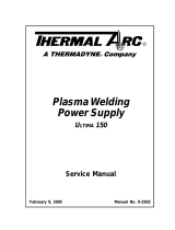
A-02401
Figure 2-1 Weld Sequencer Assembly
• Weld Sequencer Enclosure
Housing for combinations of the four modules.
Contains interface wiring and power for each unit.
Provides relay contacts for interfacing with exter-
nal controls (wire feeders, motion controls, etc).
• RP1 Control
Offers remote control for activating main contac-
tor, starting weld sequencer, starting downslope
manually, starting spot weld sequence, and adjust-
ing welding current.
• CS1 Current Slope
Allows welding current to be automatically ad-
justed from an initial current setting to a peak cur-
rent setting (upslope) and decreased automatically
to a final current setting (downslope) when sig-
naled manually or by the WT1 Weld Timer.
Upslope changes the current linearly from initial
current value to weld (peal) current value.
Downslope changes the current linearly from peak
value down to final value.
• GS1 Gas Slope (Plasma Gas)
Allows linear change in the plasma gas flow rate
(upslope and downslope) between two variable
settings. The control can be manual or automatic
when used with CS1 Current Slope
• CP1 Pulser
Reduces the amount of heat input into the weld
by pulsing the current between peak level and a
background level. The CP1 offers complete con-
trol of the pulse frequency rate and the percent-
age of 'on' time at peak current versus background
current. The CP1 also offers the capability of a lin-
ear upslope and downslope on each pulse.
• WT1 Weld Timer
Allows weld time to be set from 0.1 to 999.9 sec-
onds. When used with CS1 Current Slope the WT1
times the weld from the start of upslope to the end
of peak (weld) current at which time it provides a
signal for initiating the downslope sequence. WT1
can also be used independently as a spot weld
timer.

INTRODUCTION & DESCRIPTION 10 Manual 0-2023
2.03 Specifications & Design
Features
A. Weld Sequencer Enclosure
1. Input Power
115/230VAC, 1 Amp, 50/60 Hz
2. Control Circuit Output
28 VAC
3. Current Control
Up to 24 VDC using RP1 Control remote pendant
or some other external device.
4. Contactor Control
28 V control circuit using RP1 Control remote pen-
dant or some other external device.
5. Control Console or Power Supply Control
Control is via 10' control cable.
6. Auxiliary Connections
Relay contacts and terminal connector provided
for auxiliary input/output signals (wire feeders,
motion controls, etc.).
7. Housing Capabilities
WT1 and/or GS1; WT1 and/or CS1 and/or CP1
NOTE
For a complete Sequencer Assembly, the Enclosure
Expansion must be added on top of the Weld Se-
quencer Enclosure to accommodate CS1 and CP1
modules. Also, the enclosure expansion is required
when WT1 or GS1 is used with either CS1 or CP1.
8. Dimensions (W x H xD)
15 inches (381 mm) x 11 inches (279 mm) x 16-3/4
inches (425 mm)
With Enclosure Expansion height dimension is 18
inches (457 mm)
9. Weight
24.5 lbs (11.62 kg).
With Enclosure Expansion weight is 30 lbs
(14.23kg)
B. GS1 Gas Slope (Plasma)
1. Input Power
28 VAC from Weld Sequencer Enclosure
2. Plasma Gas Range
Min 0.5 - 3 scfh (0.25 - 1.4 lpm)
Max 2 - 7 scfh (1 - 3.3 lpm) @ 30 psi (2 bar)
3. Weight
9 lbs (4.05 kg)
C. CS1 Current Slope
1. Input Power
28 VAC from Weld Sequencer Enclosure
2. Weight
4 lbs (1.8 kg)
D. CP1 Pulser
1. Input Power
28 VAC from Weld Sequencer Enclosure
2. Pulse Rate
0.5 - 20 pulses/sec
3. Weight
3.5 lbs (1.58 kg)
E. WT1 Weld Timer
1. Input Power
28 VAC from Weld Sequencer Enclosure
2. Timing Control
Adjustable from 0.1 to 999.9 seconds
3. Weight
2.5 lbs (1.12 kg)
CAUTION
When using CS1 or CP1 with a power source other
than the Thermal Arc PS30A, the remote control
circuit must be 0 to +24 vdc and of a solid state
design.

Manual 0-2023 11 INSTALLATION PROCEDURES
SECTION 3:
INSTALLATION
PROCEDURES
3.01 Introduction
This section describes installation of the Weld Sequencer.
These instructions apply to the Weld Sequencer only; in-
stallation procedures for the Power Supply, Welding Con-
sole, Torch, Options, and Accessories are given in Manu-
als specifically provided for those units.
The complete installation consists of:
1. Site selection
2. Unpacking
3. Connections to Weld Sequencer
4. Operator training
3.02 Site Selection
The Weld Sequencer Enclosure should be located either
next to or on top of the Welding Console (GS1 connec-
tions must be installed in Welding Console before mount-
ing on top). A source of 115 or 230 VAC power must also
be available.
NOTE
Review Important Safety Precautions (page 1) to
be sure that the selected location meets all safety
requirements.
3.03 Unpacking
Each component of the system is packaged and protected
with a carton and packing material to prevent damage
during shipping.
1. Unpack each item and remove all packing material.
2. Locate the packing list(s) and use the list to identify
and account for each item.
3. Inspect each item for possible shipping damage. If
damage is evident, contact your distributor and/or
shipping company before proceeding with system
installation.
3.04 Equipment Installation -
General
WARNING
Make sure that all power to the welding system is
shut off at the incoming source. Do not turn ON
the power until all components are connected.
A. Voltage Selection
The Weld Sequencer Enclosure is factory-wired for 230V,
60Hz operation. If 230V primary power is available, con-
nect the end of the input power cord to the 230V primary
power source.
If 115V primary power is to be used change TB4 connec-
tions as follows:
1. Locate TB4 terminal strip on the rear panel of the En-
closure. Remove the two jumpers from each side of
terminals 5 and 6.
230 Volt Jumpers
TB4 Terminal Strip
A-02404
1 2 3 4 5 6 7
Figure 3-1 Jumper Installation For 230 VAC Input
2. Connect one jumper across terminals 4 and 5 and the
other across 6 and 7.
115 Volt Jumpers
TB4 Terminal Strip
A-02405
1 2 3 4 5 6 7
Figure 3-2 Jumper Installation For 115 VAC Input

INSTALLATION PROCEDURES 12 Manual 0-2023
3. Connect plug (supplied) to the end of the input power
cord per the following:
a. Feed the free end of the input power cable through
the small section of the rubber plug housing.
b. Connect the ground lead to the green terminal on
the plug.
c. Connect the other two leads to the two terminals
on the plug.
d. Press the plug into the rubber housing until the
plastic disk is captured by the rubber housing.
e. Tighten cord grip to secure input cable.
B. Cable Connections
1. Connect RP1 Control pendant to the connector on the
end of the 20 foot (6.1 m) Remote Control Cable. Con-
nect the other end of the cable to the back of the Weld
Sequencer Enclosure marked REMOTE CONTROL.
REMOTE
CONTROL
CONSOLE/POWER SUPPLY
CONTROL
A-02406
Control Cable Console/Power Supply
Control Cable
Figure 3-3 Weld Sequencer Enclosure Rear Panel
Connections
If a different remote control device is to used refer to
the Wiring Diagram supplied with the Weld Se-
quencer. The current control potentiometer must be
rated for 10k ohm at 2 watts.
Plasma Gas
Shield Gas
A-02407
Weld
Sequencer
Optional Remote
Control
Torch
Welding
Console
DC Power
Supply
Coolant Recirculator
Figure 3-4 WC100B Connections

Manual 0-2023 13 INSTALLATION PROCEDURES
2. Connect the mating plug of the 10 foot (3 m) Control
Cable to the receptacle on the rear panel of the Weld
Sequencer Enclosure marked CONSOLE/POWER
SUPPLY CONTROL.
3. The connection on the other end of the cable depends
on the welding console, power supply or current con-
trol device. Connect as follows (refer to Figure 3-4):
• Thermal Arc WC100B Welding Console
a. Connect Control Cable plug to the receptacle on
the front panel of the WC100B marked REMOTE
CONTROL. Move REMOTE ON/OFF switch to
ON position.
• Thermal Arc WC100A and WC122A (and earlier
models) Welding Consoles
b. Cut the Control Cable plug off and strip cable jacket
back approximately 2 inches.
c. Locate the cable from the welding console CON-
TROL receptacle. Measure enough cable to con-
nect with the Control Cable from the Weld Se-
quencer Enclosure and cut.
d. Connect the white/brown (J5-3) and black (J5-4)
wires of the Weld Sequencer Enclosure Control
Cable to the two leads of the cable from the weld-
ing console CONTROL. The order of connection
is unimportant. This connection gives contactor
control to the Sequencer.
e. Connect a cable to the Remote Amperage Control
of the power supply. Connect the other end to the
Weld Sequencer Enclosure Control Cable (see Fig-
ure 3-E):
Power Supply Amperage Control maximum lead
to orange wire (J5-1)
Power Supply Amperage Control variable (wiper)
lead to red wire (J5-7)
Power Supply Amperage Control minimum lead
to blue wire (J5-13)
Contactor
Control
AMP Control
(Wiper)
AMP Control
(Min)
AMP Control
(Max)
Contactor
Control
Ground
1
4
8
13
7
3
A-02408
Figure 3-5 Back View of Control Cable Plug
f. Tape back the wires not used.
• Other Welding Consoles and Power Supplies
WARNING
The remote control circuit of the welding console
or power supply must not exceed 28 volts AC or
DC.
a. Cut the cable plug off. Strip the cable jacket back
approximately 2 inches.
b. Connect the white/brown (J5-3) and black (J5-4)
wires of the Weld Sequencer Enclosure Control
Cable to the contactor control of the welding unit.
This gives contactor control to the Sequencer.
c. Connect a cable to the Remote Amperage Control
of the power supply. Connect the other end to the
Weld Sequencer Enclosure Control Cable (refer to
Figure 3-5):
Power Supply Amperage Control maximum lead
to orange wire (J5-1)
Power Supply Amperage Control variable (wiper)
lead to red wire (J5-7)
Power Supply Amperage Control minimum lead
to blue wire (J5-13)
d. Tape back the wires not used.
e. Check input power connections on the terminal
strip TB4, located on the rear panel of the Weld
Sequencer Enclosure, to be sure that they are set
up for the available voltage. Provisions are made
for primary inputs of 115 or 230 volts AC (refer to
Section 4.2) and 50 or 60 Hz power may be used.
3.05 WT1 Weld Timer
CAUTION
The WT1 Weld Timer is factory set for 60 Hz op-
eration. If 50 Hz power is used or WT1 doesn’t
time properly remove the cover from WT1 and check
the position of the switch mounted in the middle of
the PC board. Move the handle to the proper posi-
tion printed on the PC board (50 or 60).
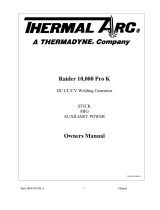
1. Install WT1 into the bottom of the opening in the Weld
Sequencer Enclosure (refer to Figure 3-6). Secure with
screws provided.
2. Connect WT1 to the Weld Sequencer Enclosure wiring
harness with the J4 connectors.

INSTALLATION PROCEDURES 14 Manual 0-2023
Enclosure Expansion
CP1 Pulser
CS1 Current Slope
WT1 Weld Timer
RP1 Control
GS1 Gas Slope
J3
J4
J7
J8
Weld Sequencer
Enclosure
A-02409
Figure 3-6 Weld Sequencer Assembly
Page is loading ...
Page is loading ...
Page is loading ...
Page is loading ...
Page is loading ...
Page is loading ...
Page is loading ...
Page is loading ...
Page is loading ...
Page is loading ...
Page is loading ...
Page is loading ...
Page is loading ...
Page is loading ...
Page is loading ...
Page is loading ...
Page is loading ...
Page is loading ...
Page is loading ...
Page is loading ...
Page is loading ...
Page is loading ...
Page is loading ...
Page is loading ...
Page is loading ...
Page is loading ...
Page is loading ...
Page is loading ...
Page is loading ...
Page is loading ...
Page is loading ...
Page is loading ...
Page is loading ...
Page is loading ...
Page is loading ...
Page is loading ...
Page is loading ...
Page is loading ...
Page is loading ...
Page is loading ...
Page is loading ...
Page is loading ...
Page is loading ...
Page is loading ...
Page is loading ...
Page is loading ...
/