GTO PRO 2000 Series User manual
- Category
- Gate Opener
- Type
- User manual

©
2000 GTO, Inc.
RB923 rev - 08/01/01
AUTOMATIC GATE OPERATOR
FOR
VEHICULAR SWING GATES
3121 Hartsfield Road • Tallahassee, Florida, USA 32303
Telephone (850) 575-0176 • FAX (850) 575-8912 • www.gtoinc.com
INSTALLATION MANUAL
FOR
THE PROFESSIONAL INSTALLER
WARNING!
READ ALL INSTRUCTIONS CAREFULLY AND COMPLETELY before attempting to install
and use this automatic gate operator. This gate operator produces a high level of force. Stay clear
of the unit while it is operating and exercise caution at all times.
This product meets and exceeds the requirements of UL 325, the standard which regulates gate operator safety,
as established and made effective March 1, 2000, by Underwriters Laboratories Inc.
SERIES
Receiver
Run 1000' (max.) of low
voltage wire to control
box from transformer.
(wire not included)
120 Volt Indoor
Transformer
(surge protector
not supplied)
PVC conduit (not included) to protect wire from lawn mowers and weed eaters.
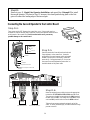
Control Box with Battery
Power Cable
Closed Position Positive Stop Plate
Gate Bracket
Post Bracket Assembly
GTO/PRO 2000
Warning Sign

VEHICULAR GATE OPERATOR CLASS CATEGORIES
Residential Vehicular Gate Operator-Class I: A vehicular gate operator (or system) intended for use in a home
of one-to-four single family dwelling, or a garage or parking area associated therewith.
Commercial/General Access Vehicular Gate Operator-Class II: A vehicular gate operator (or system) intended
for use in a commercial location or building such as a multifamily housing unit (five or more single family units),
hotel, garages, retail store, or other building servicing the general public.
Industrial/Limited Access Vehicular Gate Operator–Class III: A vehicular gate operator (or system) intended
for use in an industrial location or building such as a factory or loading dock area or other locations not intended to
service the general public.
Restricted Access Vehicular Gate Operator–Class IV: A vehicular gate operator (or system) intended for use in
a guarded industrial location or building such as an airport security area or other restricted access locations not
servicing the general public, in which unauthorized access is prevented via supervision by security personnel.
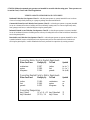
Converting Metric Units to English Equivalents
When You Know Multiply By To Find Symbol
centimeters 0.3937 inches in. (or ")
meters 3.2808 feet ft. (or ')
kilograms 2.2046 pounds lb. (or #)
Converting English Units to Metric Equivalents
When You Know Multiply By To Find Symbol
inches 2.5400 centimeters cm
feet 0.3048 meters m
pounds 0.4535 kilograms kg
Converting Temperature
deg. Celsius (ºC x 1.8) + 32 deg. Fahrenheit ºF
deg. Fahrenheit (ºF-32) / 1.8 deg. Celsius ºC
GTO/PRO 2000 series automatic gate operators are intended for use with vehicular swing gates. These operators can
be used in Class I, Class II and Class III applications.

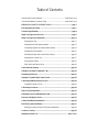
Table of Contents
Gate Operator Class Categories ----------------------------------------- inside front cover
Units and Standards Conversion Chart --------------------------------- inside front cover
IMPORTANT SAFETY INSTRUCTIONS ------------------------------------- page 1
Warning Signs and Labels ---------------------------------------------------------- page 7
Technical Specifications ------------------------------------------------------------- page 8
Single Gate Operator Parts List --------------------------------------------------- page 9
Single Gate Operator Installation ----------------------------------------------- page 11
Preparing the Gate --------------------------------------------------------------- page 11
Installing the Post Bracket Assembly ----------------------------------------- page 12
Connecting Operator to Post Bracket Assembly----------------------------- page 14
Installing the Gate Bracket------------------------------------------------------ page 15
Installing the Open and Closed Position Stops------------------------------- page 16
Mounting the Control Box ------------------------------------------------------ page 17
Powering the System ------------------------------------------------------------ page 19
Solar Zones and Gate Activity ------------------------------------------------- page 20
Control Boards Settings ----------------------------------------------------------- page 22
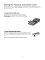
Setting the Personal Transmitter Code----------------------------------------- page 24
Mounting the Receiver ------------------------------------------------------------- page 25
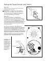
Setting the Closed Position Limit Switch--------------------------------------- page 26
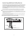
Connecting Additional Safety Devices ------------------------------------------ page 28
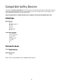
Compatible Safety Devices ----------------------------------------------------- page 29
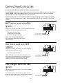
Connecting Accessories ------------------------------------------------------------ page 30
Push-To-Open Installation -------------------------------------------------------- page 31
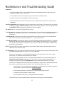
Maintenance and Troubleshooting Guide ------------------------------------- page 33
Warranty and Repair Service ---------------------------------------------------- page 35
Column Installation Information ------------------------------------------------ page 36
Dual Gate System Installation---------------------------------------------------- page 37
Setting the Control Board for Dual Gate Installations ----------------------page 40
Accessory Catalog------------------------------------------------------------------- page 42
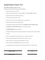
Installation Check List ------------------------------------------------------- Back Cover

1
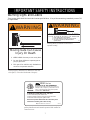
IMPORTANT SAFETY INSTRUCTIONS
Because automatic gate operators produce high levels of force, all system designers, installers, and consumers have an
obligation to know the potential hazards associated with improperly designed, installed, or maintained gate operator systems.
Keep in mind that the gate operator is just one component of the total gate operating system. Each component must work in
unison to provide the consumer with convenience, security, and safety.
This manual contains various safety precautions and warnings for the system designer, installer, and consumer. Because
there are many possible applications of the gate operator, the safety precautions and warnings contained in this manual cannot
be completely exhaustive in nature. They do, however, provide an overview of the safe design, installation, and use of this
product. CAREFULLY READ AND FOLLOW ALL SAFETY PRECAUTIONS, WARNINGS, AND INSTALLA-
TION INSTRUCTIONS TO ENSURE THE SAFE SYSTEM DESIGN, INSTALLATION, AND USE OF THIS
PRODUCT.
The precautions and warnings in this manual are identified with this warning symbol. The symbol identifies condi-
tions that can result in damage to the operator or its components, serious injury, or death.
Because GTO automatic gate operators are only part of a total gate operating system, it is the responsibility of the
designer, installer, and purchaser to ensure that the total system is safe for its intended use.
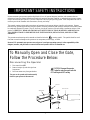
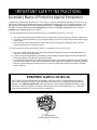
Disconnecting the Operator
1. Turn control box OFF.
2. Remove hairpin clip and clevis pin from
front mount.
3. Pull front mount away from gate bracket.
The gate can be opened and closed manually
when the gate operator is disconnected.
To Manually Open and Close the Gate,
Follow the Procedure Below:
Hairpin Clip
Clevis Pin
Gate Bracket
Front Mount
Push-Pull Tube
CAUTION: Disconnect the operator
ONLY when the control box power switch is
OFF and the gate is NOT moving.

2
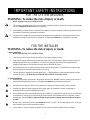
IMPORTANT SAFETY INSTRUCTIONS
FOR THE SYSTEM DESIGNER
WARNING: To reduce the risk of injury or death:
1. READ AND FOLLOW ALL INSTRUCTIONS.
2. This operator is intended for use only on vehicular gates. Pedestrians must be supplied with a separate walk-through
gate (see Entrapment Protection illustration on page 6).
3. When designing a system that will be entered from a highway or main thoroughfare, make sure the system is placed
far enough from the road to prevent traffic congestion.
4. The gate must be installed in a location that provides adequate clearance between it and adjacent structures when
opening and closing to reduce the risk of entrapment. Swinging gates shall not open into public access areas.
FOR THE INSTALLER
WARNING–To reduce the risk of injury or death:
I. Before Installation
1. READ AND FOLLOW ALL INSTRUCTIONS.
2. Verify this operator is proper for the type and size of gate, and its frequency of use.
3. Make sure the gate has been properly installed and swings freely in both directions. Repair or replace all worn or
damaged gate hardware prior to installation. A freely moving gate will require less force to operate and will
enhance the performance of the operator and safety devices used with the system.
4. Review the operation of the system to become familiar with its safety features. Understand how to manually open
and close the gate by disconnecting the operator (see page 1).
5. This gate operator is intended for vehicular gates ONLY. A separate entrance or gate must be installed for pedes-
trian use (see page 6). NO ONE SHOULD CROSS THE PATH OF A MOVING GATE.
II. During Installation
1. Install the gate operator on the inside of the property and fence line. DO NOT install an operator on the outside of
the gate where the public has access to it. Swinging gates shall not open into public access areas.
2. Be careful with moving parts and avoid close proximity to areas where fingers or hands could be pinched.
3. Installation of additional safety equipment such as safety edges (or photoelectric sensors) is suggested for
augmented protection against entrapment (see page 6).
4. Determine the best obstruction sensing setting for this installation. The gate MUST stop and reverse on contact with
an obstruction or when an object activates the non-contact sensors. After adjusting the force or the limit of travel,
retest the gate operator. Failure to adjust and retest the gate operator properly can increase the risk of injury
or death.
5. Mount access controls away from the gate (minimum distance is 10 feet). The user must have full view of the gate
but be unable to touch it while operating the controls.
6. Secure outdoor or easily accessed gate operator controls in order to prohibit unauthorized use of the gate.

3
IMPORTANT SAFETY INSTRUCTIONS
III. After Installation
1. Review ALL safety instructions with the consumer/end user. Explain the basic operation and safety systems of the
entire gate operator system, including disconnecting the operator for manual operation of the gate.
2. Attach the warning signs (included) to each side of the gate to alert public of automatic gate operation. Take a
photo of warning signs installed on gate. Record the date of the photo for your reference.
3. SAVE THESE INSTRUCTIONS.
Leave a copy of the IMPORTANT SAFETY INSTRUCTIONS section of this manual with the
consumer/end user.

4
IMPORTANT SAFETY INSTRUCTIONS
Secondary Means of Protection Against Entrapment
As specified by Underwriters Laboratories Inc. UL 325 (30A.1.1), automatic gate operators shall have provisions for, or be
supplied with, at least one independent primary and one independent secondary means to protect against entrapment. GTO
gate operators utilize Type A, an inherent entrapment sensing system, as the primary type of entrapment protection. The
GTO/PRO 2000 series gate operators have provisions for the connection of Type B1 and B2 protection to be used as a
secondary type of entrapment protection, if desired.
1. For gate operators utilizing a non-contact sensor (Type B1) in accordance with UL 325 (51.8.4 [h]):
A. Refer to the sensor manufacturer’s instructions on the placement of non-contact sensors for each type of application.
B. Care shall be exercised to reduce the risk of nuisance tripping, such as when a vehicle trips the sensor while the gate
is still moving.
C. One or more non-contact sensors shall be located where the risk of entrapment or obstruction exists, such as the
perimeter reachable by a moving gate or barrier.
2. For gate operators utilizing a contact sensor (Type B2) in accordance with UL 325 (51.8.4 [i]):
A. One or more contact sensors shall be located at the leading edge, bottom edge, and post mounted both inside and
outside of a vehicular swing gate system.
B. A hard wired contact sensor shall be located and its wiring arranged so that the communication between the sensor
and the gate operator is not subjected to mechanical damage.
C. A wireless contact sensor such as one that transmits radio frequency (RF) signals to the gate operator for entrapment
protection functions shall be located where the transmission of the signals are not obstructed or impeded by building
structures, natural landscaping or similar obstruction. A wireless contact sensor shall function under the intended
end-use conditions.
ENTRAPMENT ALARM (UL 325; 30A.1.1A)
The GTO/PRO 2000 series gate operators are designed to stop and reverse for 2 seconds when the gate comes in
contact with an obstruction or when an object activates the non-contact sensors. Additionally, these operators are
equipped with an audio entrapment alarm which will function if the unit obstructs twice while opening or closing.
This alarm will sound for a period of 5 minutes or until the operator receives an intended signal (e.g., a transmitter
signal) and the gate returns to a fully open or fully closed position.
R
E
D
B
L
K
O
R
G
B
L
U
G
R
N
C
L
S
E
D
G
O
P
N
E
D
G
R
E
D
G
R
N
O
R
G
B
L
U
W
H
T
B
L
K
O
R
G
B
L
U
G
R
N
C
L
S
E
D
G
O
P
N
E
D
G
LEARN
A
U
TO
C
LO
SE
IN
E
R
TIA
STA
TU
S
STATUS
B
A
T
T
BATT
+
–
O
B
S
TR
.
SEN
S
.
R
C
V
R
R
G
B
A
L
A
R
M
S
E
C
O
N
D
O
P
E
R
A
T
O
R
F
I
R
S
T
O
P
E
R
A
T
O
R
P
O
W
E
R
I
N
1
8
V
A
C
S
O
L
A
R
~
~
–
+
A
C
C
E
S
S
O
R
Y
P
W
R
. S
W
.
PWR. SW.
Entrapment Alarm
(bottom right of control box)

5
IMPORTANT SAFETY INSTRUCTIONS
Consumer/End User
WARNING: To reduce the risk of injury or death:
1. READ AND FOLLOW ALL INSTRUCTIONS.
2. Distribute and discuss copies of the IMPORTANT SAFETY INSTRUCTIONS with all persons authorized to use
your gate.
3. Always keep people and objects away from the gate and its area of travel.
NO ONE SHOULD CROSS THE PATH OF THE MOVING GATE.
4. Your automatic gate is not for pedestrian use. If pedestrian traffic is expected near the gate, a walk-through gate
must be installed for this purpose (see page 6).
5. Do not allow children or pets near your gate. Never let children operate or play with gate controls. Keep the
remote controls away from children and unauthorized users; store controls where children and unauthorized users
do not have access to them.
6. If push buttons or key switches are installed, they should be within sight of the gate, yet located far enough from it
(at least 10 feet) so the gate cannot be touched while it is in operation. Do not operate any control without watching
the movement of the gate.
7. Do not activate your gate operator unless you can see it and can determine that its area of travel is clear of people,
pets, or other obstructions.
8. It is your responsibility to make sure that the installer posted warning signs on both sides of your gate. If any of
these signs or warning decals become damaged, illegible or missing, replace them immediately. Contact your
installer or GTO for replacements.
9. If electric safety edge sensors (or photoelectric sensors) have been installed (see page 6) they should be tested
monthly for proper function.
10. KEEP GATES PROPERLY MAINTAINED. Clean the push-pull tube with a soft, dry cloth and apply silicone
spray to it at least once per month.
11. Have your gate operator tested monthly and serviced regularly by an experienced technician. The gate MUST stop
and reverse on contact with an obstruction or when an object activates the non-contact sensors. If these functions are
observed to operate improperly, discontinue use and have operator serviced immediately.
12. To operate this equipment safely, YOU must receive detailed instructions on disconnecting the operator for manual
gate operation (see page 1). If you feel you have not received full and proper instructions, contact your installer.
13. Disconnect the operator ONLY when the control box power switch is OFF and the gate is NOT moving.
14. SAVE THESE INSTRUCTIONS.

6
IMPORTANT SAFETY INSTRUCTIONS
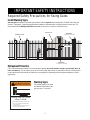
Install Warning Signs
Entrapment Protection
Required Safety Precautions for Swing Gates
Warning Signs
The warning signs (at left) must
be installed on both sides of the
gate (see page 7 for details).
1. KEEP CLEAR! Gate may move at any time.
2. Do not allow children to operate gate or
play in gate area.
3. This gate is for vehicles only. Pedestrians
must use a separate entrance.
Moving Gate Can Cause
Injury Or Death
WARNING
!
Pedestrian Gate
Vehicle Gate
Safety Edge
(recommended / not included)
Safety Edge
(recommended / not included)
Warning Sign
Warning signs alert people of automatic gate operation and are required when installing the GTO/PRO 2000 series gate
operator. Furthermore, a walk-through gate must be installed if pedestrian traffic is expected near the vehicle gate. We
recommend the GTO Bulldog Pedestrian Gate Lock (see Accessory Catalog) for controlled access.
GTO’s internal obstruction settings, even when properly adjusted, may not be sensitive enough to prevent bodily injury in
some circumstances. For this reason, safety devices such as safety edge sensors (or photoelectric sensors), which stop and
reverse gate direction upon sensing an obstruction, are suggested for augmented protection against entrapment in certain
applications.

7
IMPORTANT SAFETY INSTRUCTIONS
Warning Signs and Labels
These warning labels should be found at the locations specified below. If any of them are missing, immediately contact GTO
for replacements.
1. KEEP CLEAR! Gate may move at any time.
2. Do not allow children to operate gate or
play in gate area.
3. This gate is for vehicles only. Pedestrians
must use a separate entrance.
Moving Gate Can Cause
Injury Or Death
WARNING
!
warning signs (2 enclosed) to be installed on each side
of the gate (3–5 feet above the bottom of the gate)
RB2002
Maximum Gate: 1000 lb. (453.5 kg); 20 ft. (6.1 m)
Voltage: 12 Vdc; Frequency: 0 Hz; Power: 49.7 W
Class I, II and III Vehicular Swing Gate Operator.
Serial Number: 2000-xxxxxxx
9901178
Conforms to UL 325 STANDARDS
TO MANUALLY OPEN AND CLOSE THE GATE:
1. Turn control box power switch OFF.
2. Remove hairpin clip and clevis pin from front mount.
3. Pull front mount away from gate bracket.
Disconnect operator ONLY when the control box power
switch is OFF and the gate is NOT moving.
Series
GTO, Inc. Tallahassee, Florida USA
2000
product identification and manual operation label installed on
control box cover
1. KEEP CLEAR! Gate may move at any time.
2. Do not allow children to operate gate or play in gate area.
3. This gate is for vehicles only. Pedestrians must use
separate entrance.
WARNING
!
MOVING GATE
Can Cause Injury or Death
RB979
warning labels (2) installed on each side of
operator housing
L
I
S
T
E
D
¤
US
C

8
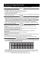
GTO/PRO 2000 Series Swing Gate Operators
These Specifications are subject to change without notice.
Technical Specifications
DRIVE
• Low friction screw drive (linear actuator).
• Temperature rating of motor -30 ºF (-34 ºC) to +160 ºF (71ºC).
• Powered by a 12 Vdc motor; generates 650 ft. lb. of torque at 12 V.
• 110
o
degree opening time approximately 15 to 20 s.
•Maximum push-pull tube stroke 24”.
• Operator length with push-pull tube fully retracted is 39” (99 cm), mounting point to mounting point.
• Limit switches are internal.
POWER
• System is powered by a 12 Vdc, 7.0 Ah, sealed, rechargeable battery.
• Battery charge maintained by 120 Vac, 60 Hz input and 18 Vac at 40 VA (2.9 A) output; transformer
rectified to 14.5 Vdc through the GTO Control Board. Control board fuses (2) are rated for 15 A.
NOTE: DO NOT connect transformer directly to any battery. Do not replace fuses with higher
ampere rated fuses; doing so will void your warranty and may damage your control board
.
• Battery charge maintained by GTO Solar Panel Charger: float voltage 14.5 Vdc output from
19
3
/
8
" x 15
1
/
4
" silicon alloy panel; generates minimum of 10 W at 600 mA. Gated diode on control
board prevents battery discharge.
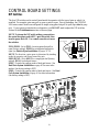
CONTROL
• GTO microprocessor-based control board is set for single leaf, pull-to-open gate installations. DIP
switches can be adjusted to accommodate an optional kit for push-to-open gates (see Accessory
Catalog).
• Control board has temperature compensated circuits.
•A circuit on the control board regulates charging. "Sleep draw" is 40 mA; "active draw" is 2 to 5 A.
• Auto-memorization of digital transmitter code.
• GTO remote-mounted RF receiver tuned to 318 MHz.
• adjustable auto-close timer (OFF to 120 s), inertia, and obstruction sensitivity using three (3)
potentiometers.
• Power terminal bock accommodates a transformer and solar panels.
• DIP switches simplify setup of gate operator.
• Accessory terminal block fully compatible with push button controls, digital keypads, safety loops, card
readers, etc.
• Control board allows connection of safety edge sensors and photoelectric sensors.
• Audio entrapment alarm sounds if unit encounters an obstruction twice while opening or closing.
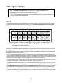
OPERATIONAL CAPACITY
• The GTO/PRO 2000 series will move gates weighing up to 1000 lb. (453 kg) and up to 20 ft. (6.1 m)
in length provided all installation procedures have been followed. Ball bearing hinges should be
used on all gates weighing over 250 lb. (113.4 kg).
• The GTO/PRO 2000 series operators are capable of continuous duty cycling. For questions about
specific applications and information regarding cycling duty when charged by solar panels, call the
GTO service department at (800) 543-GATE [4283] or (850) 575-0176.
Gate Weight
Gate Length
Gate Capacity Chart (estimated number of cycles based on use with a transformer)
1000 lb.
800 lb.
600 lb.
400 lb.
200 lb.
160
170
180
190
200
6-8 ft.
150
160
170
180
190
10 ft.
140
150
160
170
180
12 ft.
130
140
150
160
170
14 ft.
120
130
140
150
160
16 ft.
110
120
130
140
150
18 ft.
100
110
120
130
140
20 ft.

9
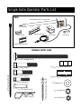
Hairpin Clip (1)
1
/
2
" x 1
1
/
4
" Clevis Pin (1)
3
/
8
" x 1
1
/
2
" Bolt (1)
1
/
2
"dia x 1
7
/
16
" Metal Spacer (1)
1
1
/
4
"
dia
x
1
/
2
" Nylon Spacer (2)
1
/
2
" x 2
3
/
4
" Bolt (3)
1
/
2
" x 3
3
/
4
" Bolt (2)
1
/
2
" x 10" Carriage Bolt (2)
8" Nylon Cable Tie (14)
1
/
2
" Washer (6)
1
/
2
" Lock Nut (7)
3
/
8
" Lock Nut (1)
2" Receiver Mounting Screw (4)
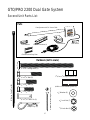
Installation of First (Single) Gate Operator
Single Gate Operator Parts List
Closed Position Stop Plate
Gate Operator with 6 ft. Power Cable
Post Bracket
Post Pivot Brackets (2)
Gate Bracket
Rear Mount
Hardware (not to scale)
Parts

10
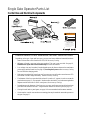
Control Box and Electrical Components
Single Gate Operator Parts List
OTHER MATERIALS YOU MAY NEED BEFORE YOU START THE INSTALLATION:
Depending on the type of gate and fence post, you may need some additional materials/hardware.
Some of these items can be found in the GTO/PRO Accessory Catalog.
• All gates will need a stop post in the open position. This post is not provided. See page 16,
Installation of Open and Closed Position Stops for more information.
• Low voltage wire may be needed. Length depends upon the distance between the transformer
power supply and the control box. See page 19, Powering the System and the Accessory Catalog
for wire and solar charging panels.
• If the gate is more than 1000' away from an AC power source you will need to use at least one GTO
Solar Panel to trickle charge the battery. See the Accessory Catalog.
• The diameter of the fence post should be at least 8" (round) or 6" (square) in order to mount the
post bracket (see page 12). An optional 4” bracket can be used with 4” post, and mounting bracket
adapters must be used with 4" and 6" round posts. (See Accessory Catalog).
• Depending upon the diameter of the fence post, you may need longer carriage bolts than those
provided. Bolts should be at least 1" longer than the diameter of the fence post (see page 12).
• If using thin wall tube or panel gates, see page 14 for recommended reinforcement materials.
•A horizontal or vertical cross member or mounting plate may be needed to mount the operator to
the gate. See page 11.
1. KEEP CLEAR! Gate may move at any time.
2. Do not allow children to operate gate or
play in gate area.
3. This gate is for vehicles only. Pedestrians
must use a separate entrance.
Moving Gate Can Cause
Injury Or Death
WARNING
!
RB3270

11
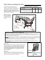
Preparing the Gate
Step 1:
The gate must be in proper working order, plumb, level and swinging freely on its hinges. Do not use wheels on gate. The
gate must move smoothly and evenly throughout its swing, without binding or dragging on the ground. Gates over 250 lb.
should have ball bearing hinges with grease fittings.
Step 2:
The fence post must be strongly secured in the ground with
concrete so it will not twist or flex when the operator is
powered. It is important to position the operator near the
midline of the gate to keep the gate from twisting and
flexing. The addition of a horizontal or vertical cross
member may be necessary (if one is not already in place)
to provide a stable area to which the gate bracket can be
secured.
For the operator to perform properly, Steps 1 & 2 must
be complete before you go any further with the installa-
tion.
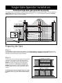
Pull-to-Open Single Gate (gate opens into the property)
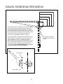
The diagram below is an example of a single leaf, pull-to-open installation on an ornamental iron gate. If you are installing a
Push-to-Open (gate opens out from the property) system, see page 31. Or, if you are mounting the operator on a masonry
column, please refer to page 36 before proceeding.
Single Gate Operator Installation
Horizontal Cross Member
Vertical Cross Member
Receiver
Run 1000' (max.) of low
voltage wire to control
box from transformer.
(wire not included)
120 Volt Indoor
Transformer
(surge protector
not supplied)
PVC conduit (not included) to protect wire from lawn mowers and weed eaters.
Control Box with Battery
Power Cable
Closed Position Positive Stop Plate
Gate Bracket
Post Bracket Assembly
GTO/PRO 2000
Warning Sign

12
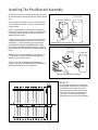
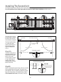
Installing The Post Bracket Assembly
The position of the post bracket determines the leverage of
the operator and the clearance between the operator and the
gate.
The post bracket is designed to work on a flat fence post.
Fence posts must be at least 6” square in order to mount
the post bracket.
NOTE: The best method of attaching the post bracket to
metal post is welding. Round wood posts (no smaller than
8” diameter) may be notched to create a flat surface for
attaching the post bracket.
If bolts are used to mount the post bracket, the bolts must
completely penetrate the fence post. If your fence post is
wider than 8", it will be necessary to use carriage bolts
longer than those supplied. On wood posts use a metal
plate (not provided) between the nuts and post to prevent
the operator from pulling the bolts and washers through the
wood.
NOTE: If you have round metal gate posts that are 4” or
6” in diameter, optional mounting bracket adapters are
available, see Accessory Catalog.
The use of optional mounting brackets adapters may
require you to drill a few additional holes in the standard
post bracket depending on your application.
Step 3:
Close the gate and place your level against
the horizontal cross member. The top of the
level should be in the center of the cross
member and should overlap the fence post.
Scribe a line across the cross member and
fence post. You will use this line to help
determine position of gate and post brackets.
Level
4” Metal Post
6” Metal Post
8” Wood Post
6” Wood or Metal Post
Standard Post Bracket (included)
Optional Mounting Bracket Adapters

13
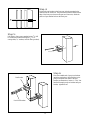
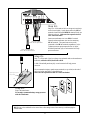
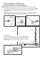
Step 6:
Place the rounded ends of post pivot brackets
inside the post bracket. Align the holes in the
post pivot brackets with holes in the post
bracket (see illustration). Insert
1
/
2
" x 3
3
/
4
" hex
head bolt through post pivot brackets and post
bracket; tighten the nut.
Step 5:
Drill holes in fence post as marked using a
1
/
2
" drill
bit. Install the post bracket using the
1
/
2
" x 10"
carriage bolts,
1
/
2
" washers, and lock nuts (provided).
Step 4:
Position the post bracket on the fence post with the mounting holes
centered over the scribe line. The post bracket should be flush with the
edge of the fence post closest to the gate (see illustration). Mark the
position of post bracket holes on the fence post.
Post Bracket
Post Pivot Brackets

14
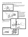
IMPORTANT: Thin walled tube and
panel gates MUST be reinforced as
shown to prevent damage to gate and
operator.
Step 8:
Position rear mount between post pivot
brackets. Place
1
/
2
" washers between
rear mount and post pivot brackets.
Align
1
/
2
" hole in rear mount and
washers with holes in post pivot
brackets. Attach the rear mount to post
pivot brackets using
1
/
2
" x 2
3
/
4
" bolt
and
1
/
2
" nut. Note: when tightening
the rear mount bolt, leave it loose
enough for the operator to pivot
freely.
Step 9:
Attach the gate bracket to the front
mount using the clevis pin and hairpin
clip.
Step 7:
Tap the rear mount onto the back of the operator. Align the
3
/
8
" hole in the rear mount with
3
/
8
" hole in the back of the
operator and insert the
3
/
8
" bolt through the holes and
secure it with the lock nut.
Connecting Operator to Post Bracket Assembly
Rear Mount
Post Pivot Brackets
1
/
2
" Washers
Rear Mount
Hairpin Clip
Clevis Pin
Gate Bracket
Front Mount
Push-Pull Tube

15
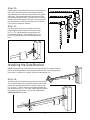
Step 10:
Open the gate to the desired position (at least 10º and no greater
than 110º). Position the operator so that the gate bracket just
rests against the gate. Check the clearance between the operator
and the gate. The operator should only make contact with the
gate at the gate bracket. However, there should not be too much
clearance between the operator and the gate, or the operator will
fully extend before it reaches the closed position. See illustra-
tion at right for examples of clearance.
Step 11:
Now align spacer and post pivot brackets hole with the
post bracket hole that provides the best clearance. Insert
the
1
/
2
" x 3
3
/
4
" bolt through holes in post bracket, post
pivot brackets and spacer. When tightening the
1
/
2
" nut,
leave it loose enough so that you can make adjustments
later.
Installing the Gate Bracket
Spacer
Step 12:
With the gate bracket clamped in the open position (no more than
110
o
from the closed position). Detach the operator from the gate
bracket. The mounting holes should be centered over the scribe
line. Drill the
1
/
2
" holes in the gate cross member and attach the
gate bracket using the
1
/
2
" x 2
3
/
4
" bolts, washers and nuts. Reattach
the operator to the gate bracket. You have now established the
OPEN POSITION of the gate.
NOTE: Rotating the front mount at the end of the push-pull tube will change its length so
that the mount and gate bracket can be properly aligned with each other on the gate at the
best location (i.e. between or on pickets, on braces, mounting plate, etc.).

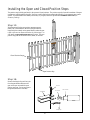
16
Step 14:
Remove the hairpin clip and clevis pin
from the gate bracket and move the
gate so that you can install the open
position stop post. Secure stop post in
the ground (and seat in concrete).
Installing the Open and Closed Position Stops
Step 13:
With the gate still in the open position, measure approxi-
mately 3/4 of the distance to the end of the gate from the
hinges and place a mark on the ground directly under the gate
(refer to the overview illustration below for positioning). You
will install an open-position stop post at this point. The open
position stop post can be made of wood, metal, or concrete.
Closed Position Stop
Open Position Stop
Hairpin Clip
Clevis Pin
Gate Bracket
Front Mount
Push-Pull Tube
The positive stops hold the gate firmly in the open and closed positions. The positive stops also form the boundaries of the gate
operating arc and help stabilize the gate. Moreover, a stable gate helps to maintain the long life of your automatic gate opener
system. To further enhance the stability and security of your gate, install the optional GTO Automatic Gate Lock (see
Accessory Catalog).

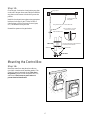
17
Step 15:
Close the gate. Position the closed position stop plate
on the end of the gate frame at mid-height. Extend the
stop plate to make contact with the fence post at that
position.
Install the closed position stop plate using appropriate
hardware for the type of gate (U-bolts for tube or
chain link gate, wood or lag screws for wood gates,
etc.). This hardware is not provided.
Reattach the operator to the gate bracket.
Mounting the Control Box
Step 16:
Mount the control box using the nylon cable ties
(provided) or another secure mounting method. The
control box must be mounted at least 3 feet above
the ground to protect it from rain splash, snow, etc.,
and at least 3 feet from an ac power source to
prevent electrical interference.
Closed Position
Stop Plate
Closed Position Stop Plate mounted
on metal post with u-bolts.
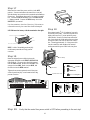
Open Position Stop
Wood, metal or concrete
post set in concrete.
Hinge point
The gate must open no more than 110°
Fence Post
Gate Post
TOP VIEW
SIDE VIEW
Page is loading ...
Page is loading ...
Page is loading ...
Page is loading ...
Page is loading ...
Page is loading ...
Page is loading ...
Page is loading ...
Page is loading ...
Page is loading ...
Page is loading ...
Page is loading ...
Page is loading ...
Page is loading ...
Page is loading ...
Page is loading ...
Page is loading ...
Page is loading ...
Page is loading ...
Page is loading ...
Page is loading ...
Page is loading ...
Page is loading ...
Page is loading ...
Page is loading ...
Page is loading ...
Page is loading ...
Page is loading ...
-
 1
1
-
 2
2
-
 3
3
-
 4
4
-
 5
5
-
 6
6
-
 7
7
-
 8
8
-
 9
9
-
 10
10
-
 11
11
-
 12
12
-
 13
13
-
 14
14
-
 15
15
-
 16
16
-
 17
17
-
 18
18
-
 19
19
-
 20
20
-
 21
21
-
 22
22
-
 23
23
-
 24
24
-
 25
25
-
 26
26
-
 27
27
-
 28
28
-
 29
29
-
 30
30
-
 31
31
-
 32
32
-
 33
33
-
 34
34
-
 35
35
-
 36
36
-
 37
37
-
 38
38
-
 39
39
-
 40
40
-
 41
41
-
 42
42
-
 43
43
-
 44
44
-
 45
45
-
 46
46
-
 47
47
-
 48
48


GTO PRO 2000 Series User manual
- Category
- Gate Opener
- Type
- User manual
Ask a question and I''ll find the answer in the document
Finding information in a document is now easier with AI
Related papers
-
GTO SL-6100 Installation guide
-
-
GTO SL800 Installation guide
-
-
GTO SL-2000 User manual
-
-
-
-
-
Other documents
-
 Mighty Mule FM132 Operating instructions
-
Bulldog Security F8E500 User manual
-
 Mighty Mule Automatic Gate Opener System Installation guide
-
 Mighty Mule MM-SL2000B User manual
-
 Mighty Mule MM260 User manual
-
 Mighty Mule MM260 Operating instructions
-
 Mighty Mule RB509-500 Installation guide
-
 Mighty Mule FM200 Installation guide
-
 Mighty Mule MMDIA30D Operating instructions
-
 Mighty Mule MM360-SOL Operating instructions


