Blade 500 3D User manual
- Category
- Toys & accessories
- Type
- User manual
This manual is also suitable for

Instruction Manual
Bedienungsanleitung
Manuel d’utilisation
Manuale di Istruzioni
500 Bell 222 Body Set
®
®
®

2
WARNING: Read the ENTIRE instruction manual to become familiar with the features of the product before operating. Failure to operate the product correctly can result in
damage to the product, personal property and cause serious injury.
This is a sophisticated hobby product for advanced helicopter pilots with previous experience in the operation of CCPM helicopters (Cyclic Collective Pitch Mixing or Collective Pitch
Helicopter) such as the Blade SR or the Blade mCP X. It must be operated with caution and common sense and requires some basic mechanical ability.
Failure to operate this product in a safe and responsible manner could result in injury or damage to the product or other property. This product is not intended for use by children
without direct adult supervision. Do not attempt disassembly, use with incompatible components or augment product in any way without the approval of Horizon Hobby, Inc. This
manual contains instructions for safety, operation and maintenance. It is essential to read and follow all the instructions and warnings in the manual, prior to assembly, setup or use,
in order to operate correctly and avoid damage or serious injury.
WARNUNG: Lesen Sie die GESAMTE Bedienungsanleitung, um sich vor Inbetriebnahme mit den Funktionen des Produkts vertraut zu machen. Eine nicht ordnungsgemäße
Bedienung des Produkts kann das Produkts und persönliches Eigentum schädigen und schwere Verletzungen verursachen.
Dieses ist ein anspruchvolles Hobby Produkt für den fortgeschrittenen Hubschrauberpiloten mit Erfahrung von Pitchgesteuerten (CCPM) Hubschraubern ((Cyclic Collec-
tive Pitch Mixing oder Collective Pitch Helicopter) wie zum Beispiel dem Blade SR oder dem Blade mCP X. Es muss mit Vorsicht und Umsicht bedient werden und erfordert einige
mechanische Grundfertigkeiten.
Dies ist ein hoch entwickeltes Produkt für den Hobbygebrauch. Es muss mit Vorsicht und Umsicht bedient werden und erfordert einige mechanische Grundfertigkeiten. Wird das
Produkt nicht sicher und umsichtig verwendet, so könnten Verletzungen oder Schäden am Produkt oder anderem Eigentum entstehen. Dieses Produkt ist nicht für den Gebrauch
durch Kinder ohne direkte Aufsicht eines Erwachsenen vorgesehen. Versuchen Sie nicht, das Produkt ohne Zustimmung von Horizon Hobby, Inc. zu zerlegen, mit nicht-kompatiblen
Komponenten zu verwenden oder beliebig zu verbessern. Dieses Handbuch enthält Sicherheitshinweise sowie Anleitungen zu Betrieb und Wartung. Es ist unerlässlich, dass Sie
alle Anleitungen und Warnungen in diesem Handbuch vor dem Zusammenbau, der Einrichtung oder der Inbetriebnahme lesen und diese befolgen, um eine korrekte Bedienung zu
gewährleisten und Schäden bzw. schwere Verletzungen zu vermeiden.
The following terms are used throughout the product literature to indicate various levels of potential harm when operating this product:
The purpose of safety symbols is to atttract your attention to possible dangers. The safety symbols, and their explanations, deserve your careful attention and understanding. The
safety warnings do not by themselves eliminate any danger. The instructions or warnings they give are not substitutes for proper accident prevention measures.
NOTICE: Procedures, which if not properly followed, create a possibility of physical property damage AND a little or no possibility of injury.
CAUTION: Procedures, which if not properly followed, create the probability of physical property damage AND a possibility of serious injury.
WARNING: Procedures, which if not properly followed, create the probability of property damage, collateral damage, serious injury or death OR create a high probability of superfi -
cial injury.
Die folgende Begriffe werden in der gesamte Produktliteratur verwendet, um die Gefährdungsstufen im Umgang mit dem Produkt zu defi nieren:
Der Zweck der Sicherheitssymbole ist es Ihre Aufmerksamkeit auf mögliche Gefahren zu lenken. Die Symbole und ihre Erklärungen erfordern ihre sorgfältige Aufmerksamkeit und
Verstehen. Die Symbole eliminieren nicht die Gefahr. Die Anweisungen und Warnungen ersetzen nicht angemessene und korrekte Unfallverhütungsmaßnahmen.
HINWEIS: Verfahren können bei nicht ordnungsgemäßer Durchführung womöglich Schäden an physischem Eigentum UND geringfügige oder keine Verletzungen verursachen.
ACHTUNG: Verfahren können bei nicht ordnungsgemäßer Durchführung womöglich Schäden an physischem Eigentum UND schwere Verletzungen verursachen.
WARNUNG: Verfahren können bei nicht ordnungsgemäßer Durchführung möglicherweise Schäden an Eigentum, Kollateralschäden UND schwere Verletzungen bis zum Tot ODER
höchstwahrscheinlich oberfl ächliche Verletzungen verursachen.
NOTICE
HINWEIS
All instructions, warranties and other collateral documents are subject to change at the sole discretion of Horizon Hobby, Inc. For up-to-date product literature, visit horizonhobby.
com and click on the support tab for this product.
Alle Anweisungen, Garantien und dazugehörigen Dokumente können ohne Ankündigung von Horizon Hobby Inc. geändert werden. Eine aktuelle Version ersehen Sie bitte im Support
Feld unter: http://www.horizonhobby.com.
Meaning of Special Language
Begriffserklärung
WARNING: Failure to follow all instructions can lead to damage to your helicopter, property damage and bodily injury or death.
WARNUNG: Das nicht befolgen dieser Anweisungen kann zu Beschädigung des Hubschraubers, Sachbeschädigungen und/oder Körperverletzungen bis hin zum Tod führen.
CAUTION: Do not make changes or adjustments to the product not shown in the instruction manual.
ACHTUNG: Nehmen Sie keine Änderungen oder Einstellungen an dem Produkt vor die nicht in der Bedienungsanleitung abgebildet sind.
CAUTION: Please refer to your Blade 500 manual for all safety precautions and warnings for the use and maintenance of your helicopter.
ACHTUNG: Bitte lesen Sie die Bedienungsanleitung ihres Blade 500 für alle Warnungen, Sicherheitshinweise und Wartungsinformationen
Safety Alert: Indicates a warning or caution. Attention is required in order to avoid serious personal injury.
Sicherheitsalarm: Zeigt eine Warnung oder Vorsichtmaßregel an. Hier ist Aufmerksamkeit erforderlich um ernste Körperverletzungen zu vermeiden.
Page is loading ...

4
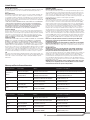
Tools Required/Erforderliches Werkzeug/Outils requis/Attrezzi necessari
1.5mm Hex 1,5mm Inbus Clé hexagonale 1.5mm 1,5mm esagonale
2mm Hex 2,0mm Inbus Clé hexagonale 2mm 2,0mm esagonale
2.5mm Hex 2,5mm Inbus Clé hexagonale 2.5mm 2,5mm esagonale
2.5mm Hex (150mm long) 2,5mm Inbus lang Clé hexagonale 2.5mm (longueur 150mm) 2,5mm esagonale (lunga 150mm)
Phillips Screw Driver Philips Schraubendreher Tournevis cruciforme Cacciavite a stella
Hemostats Klemme Pince hémostatique Pinzette
Needle nose pliers Spitzzange Pince à becs fi ns Pinze a becchi stretti
CA Glue Med CA Sekundenkleber Colle CA moyenne Colla CA media
Hot Glue Gun Heißkleber Pistolet à colle chaude Pistola per colla a caldo
Scissors Schere Ciseaux Forbici
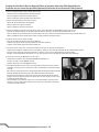
CAUTION: Before fl ying your helicopter with the Bell
®
222
®
body installed, please be aware that the fl ying characteristics of the helicopter will change.
The Blade 500 3D and Blade 500 X helicopters fl y very smooth and scale-like with the Bell 222 body installed, however controls will be slower to
respond. The helicopter will still be capable of loops, rolls and inverted fl ight, but aggressive 3D maneuvers or backward fl ight should not be attempted.
Doing so increases the possibility of a boom-strike or the loss of the front hatch.
ACHTUNG: Bevor Sie ihren Hubschrauber mit dem Bell 222 Rumpf fl iegen müssen Sie wissen, dass sich die Flugcharakteristik des Hubschraubers ändert.
Der Blade 500 3D und der Blade 500X fl iegen mit dem montieren Rumpf mehr Scale und die Reaktion des Hubschrauber verlangsamt sich. Der Hub-
schrauber fl iegt noch Loopings, Rollen und Rückenfl ug, aber aggressive 3D Manöver oder Rückwärtsfl ug sollten vermieden werden. Es besteht dabei die Gefahr
der Heckrotorberührung oder des Verlustes der vorderen Rumpfhaube.
ATTENTION: Avant de faire voler votre hélicoptère avec le fuselage de Bell 222 installé, veuillez prendre conscience que les caractéristiques de vol de
l’hélicoptère vont être modifi ées. Le Blade 500 3D et le Blade 500X volent en douceur et de façon réaliste quand le fuselage de Bell 222 est installé,
les commandes répondront donc plus lentement. L’hélicoptère reste capable d’effectuer des boucles, des tonneaux et de vol inversé, cependant les fi gures 3D
agressives ou le vol en marche arrière ne doivent pas être tentés, sous peine d’obtenir un décrochage de l’anticouple ou la perte de la trappe avant amovible.
ATTENZIONE: prima di far volare l’elicottero con la fusoliera del Bell 222, bisogna essere consapevoli che le caratteristiche di volo cambieranno. Gli elicot-
teri Blade 500 3D e il Blade 500X con la fusoliera Bell 222 installata hanno un volo molto regolare, tipo riproduzione, quindi i comandi saranno più lenti
nella risposta. L’elicottero sarà ancora in grado di eseguire looping, tonneau e volo rovescio, ma non sarà più possibile fare l’acrobazia aggressiva 3D o il volo
all’indietro. Qualora si tentasse di farli, si aumenterebbe la possibilità di rompere il tubo di coda o di perdere lo sportello anteriore.
Page is loading ...

6
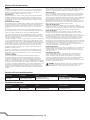
6. Make sure that all parts (servos, linkages, and the main shaft) are in perfect working order. If they are not, they can cause vibration that will be amplifi ed
through the fuselage and damage the helicopter during fl ight. Test fl y the helicopter before installing the fuselage, as adjustments to the AR7200BX Receiver/
Flybarless System will be impossible after installation.
Stellen Sie bitte sicher, dass alle Teile (Servo, Anlenkungen und die Rotorwelle) perfekt arbeiten. Falls nicht, könnte dieses Vibrationen hervorrufen die durch den
Rumpf verstärkt werden und den Hubschrauber im Flug beschädigen. Testen Sie den Hubschrauber bevor Sie die Haube montieren, da spätere Einstellungen
am AR7200BX System mit montierter Haube nicht möglich sind.
Contrôlez l’état de toutes les pièces (Servos, tringleries et axe principal). Si elles ne sont pas en parfait état, elles peuvent causer des vibrations qui seront
amplifi ées par le fuselage et provoqueront des dommages à l’hélicoptère durant le vol. Essayez l’hélicoptère avant d’installer le fuselage, effectuez également
les réglages du module fl ybarless AR7200BX car après l’installation du fuselage les réglages seront impossibles à effectuer.
Accertarsi che tutte le parti (servi, collegamenti e albero principale) siano in perfetta effi cienza. Se non lo fossero, potrebbero causare vibrazioni che sareb-
bero ulteriormente amplifi cate attraverso la fusoliera, danneggiando l’elicottero mentre è in volo. Eseguire una prova di volo dell’elicottero prima di montare la
fusoliera, facendo le regolazioni del ricevitore/sistema fl ybarless AR7200BX perché sarebbero impossibili da fare dopo l’installazione.
Installing the Foam Damping in the Fuselage/Montage der Schaumdämpfer im Rumpf/
Installation de la mousse anti-vibration dans le fuselage/Installare la gomma piuma ammortizzante nella fusoliera
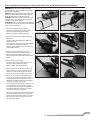
1. Refer to the photos to determine the foam mounting locations.
Bitte entnehmen Sie den Fotos die Positionen der Schaumdämpfer.
Référez-vous à la photo pour déterminer les emplacements de la pose de la mousse.
Fare riferimento alle foto per individuare la posizione di montaggio.
2. Cut the foam sheet to fi t the mounting locations.
Schneiden Sie die Schaumstücke passend zum Montageort.
Coupez la plaque de mousse pour l’adapter à l’emplacement où elle doit être posée.
Tagliare il foglio di gomma piuma per adattarlo alle posizioni di montaggio.
3. Secure the foam sheet in the fuselage using hot glue.
Befestigen Sie Schaumstücke mit Heißkleber.
Collez la plaque de mousse en utilisant de la colle chaude.
Fissare le gomma piuma nella fusoliera usando colla a caldo.
4. Allow the glue to cool and make sure the foam is secure before installing the helicopter frame in the body.
Lassen Sie den Heißkleber abkühlen und stellen sicher dass der Schaum fest gesichert ist.
Laissez la colle refroidir et contrôlez qu’elle tient parfaitement en place avant d’installer le châssis de l’hélicoptère dans le fuselage.
Lasciare che la colla si raffreddi e verifi care che sia fi ssata bene prima di inserire il telaio dell’elicottero nella fusoliera.
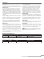
Mount installation/Einbau der Trägerplatte/Installation de la platine de fi xation/Installazione del supporto
1. Locate (four) 3mm washers and socket head cap screws.
Legen Sie die vier (4) Unterlegscheiben und
Inbusschrauben bereit.
Repérez 4 vis BTR M3 ainsi que 4 rondelles M3.
Individuare le (4) rondelle da 3 mm e le viti con testa a
brugola.
2. Install a washer on each cap screw and press the screws
through the mounting plate as shown. Tighten the screws
so the mount is fl at against the frame.
Setzen Sie eine Unterlegscheibe auf jede Schraube und
die Schraube auf die Öffnung in der Trägerplatte. Ziehen
Sie die Schrauben so an, dass die Trägerplatte am
Chassis anliegt.
Placez une rondelle sur chacune des vis et pressez
les vis au travers de la platine de montage comme sur
l’illustration. Serrez les vis de façon à plaquer la platine à
plat contre le châssis.
Inserire una rondella in ogni vite, premendola attraverso
la piastra di montaggio, come illustrato. Stringere le viti
in modo che il supporto si appiattisca contro il telaio.
Page is loading ...

8
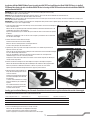
2. Use the wood screws to secure the landing gear mounts in the fuselage.
Sichern Sie die Halter im Rumpf mit den Holzschrauben.
Utilisez les vis à bois pour fi xer les supports dans le fuselage.
Usare le viti da legno per fi ssare alla fusoliera i supporti per il carrello.
3. Slide the wheels onto the axles and secure them using the wheel collars. Place a small drop of threadlock on each wheel collar setscrew.
Schieben Sie die Räder auf die Achsen und sichern diese mit den Stellringen. Geben Sie einen kleinen Tropfen Schraubensicherungslack auf jede
Madenschraube am Stellring.
Glissez les roues sur les axes des jambes de train et maintenez-les à l’aide des bagues d’arrêt. Mettez une petite goutte de frein fi let sur les vis
sans tête des bagues.
Inserire le ruote nei loro assi e fi ssarle con i collari. Mettere una goccia di frenafi letti per fi ssare il grano di ogni collare.
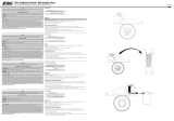
Installing the Helicopter Tail/Montage des Hubschrauberleitwerks/Installation de la dérive de l’hélicoptère/
Installazione della coda dell’elicottero
1. Install the tail case on the tail boom. It is normal for the foam dampers to move forward when you install the tail case.
Montieren Sie das Heckrotorgehäuse am Heckrohr. Es ist normal, dass sich bei der Montage die Schaumdämpfer nach
vorne bewegen.
Installez le boîtier d’anticouple sur la poutre. Le déplacement vers l’avant des absorbeurs est normale durant
l’installation du boîtier d’anticouple.
Installare la scatola di coda nel tubo di coda. È normale che gli smorzatori di spugna si muovano in avanti quando si fa
questa operazione.
2. Locate the two Phillips screws and two washers. Put a washer on each of the screws.
Nehmen Sie die beiden Phililps Schrauben und zwei Unterlegscheiben zur Hand. Stecken Sie eine Unterlegscheibe auf
jede Schraube.
Repérez les deux vis cruciforme et les deux rondelles. Placez une rondelle sur chacune des vis.
Individuare le due viti con testa a croce con le loro rondelle. Mettere una rondella in ogni vite.
3. Press the screws through the vertical fi n and put a spacer on each screw. The spacers align the vertical fi n with the
fuselage.
Drücken Sie die Schrauben durch Leitwerksfi nne und setzen je ein Distanzstück auf jede Schraube. Die Distanzstücke
richten die Finne am Rumpf aus.
Passez les vis au travers de la dérive et placez une entretoise sur chaque vis. Les entretoises servent à aligner la
dérive par rapport au fuselage.
Premere le viti attraverso l’impennaggio verticale e mettere un distanziale in ogni vite. I distanziali servono per al-
lineare l’impennaggio verticale alla fusoliera.
4. Tighten the screws in the holes used for the original vertical fi n.
Ziehen Sie die Schrauben in den Originallöchern an.
Serrez les vis dans les trous utilisez pour la fi xation de la dérive d’origine.
Stringere le viti nei fori usati per fi ssare l’impennaggio verticale originale.
Installing the Lights (Optional)/Einbau der optionale Beleuchtung/
Installation des éclairages (Optionnel) /Installazione delle luci (opzionali)
If you wish to install the optional lights, you will need to purchase the following items:
Wenn Sie die optionale Beleuchtung verwenden möchten benötigen Sie dafür die folgenden Teile:
Si vous désirez installer les éclairages optionnels, vous devrez acheter les éléments suivants :
Se si volessero installare le luci opzionali, sarebbe necessario acquistare i seguenti articoli:
EFLA600 Controller Controller Unité de contrôle Controller
EFLA607 Red LED Flashing light (2) Rote LED blinkend (2) LED rouge clignotante (2) LED rosso lampeggiante (2)
EFLA601 Red LED Solid Rote LED leuchtend LED rouge fi xe LED rosso a luce fi ssa
EFLA604 Green LED Solid Grüne LED leuchtend DEL verte fi xe LED verde a luce fi ssa
EFLA616 Y-harness 12 inch Y-Kabel 12-inch Cordon Y long. 30cm Prolunga a Y da 30 cm ca.
EFLA614 Extension 12 inch (4) Verlängerung 12-inch (4) Rallonge long.30cm (4) Prolunga normale da 30 cm ca. (4)

9
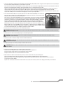
1. Use a pair of hemostats to install the lower fl ashing light. Install a Red Flashing LED (EFLA607) in both the upper and lower light fi xtures. Use a drop of CA glue
to secure the LED in the light fi xture. Add a 12-inch extension to each LED.
Setzen Sie mit einer Pinzette das untere Blinklicht in Fassung. Setzten Sie je eine rote blinkende LED (EFLA607) in die obere und untere Aufnahme. Sichern Sie
die LED mit einem Sekundenkleber. Verlängern Sie die Anschlußkabel mit einer 12 inch Verlängerung an jede LED.
Utilisez une pince hémostatique pour installer la DEL clignotante inférieure. Installez une DEL rouge clignotante (EFLA607) dans l’ emplacement inférieur et
supérieur. Utilisez une goutte de colle CA pour maintenir les DELs dans leurs emplacements. Ajoutez une rallonge de 30cm de long à chaque DEL.
Usare delle pinzette per installare la luce lampeggiante inferiore. Mettere un LED rosso lampeggiante (EFLA607) nelle sedi per luci inferiore e superiore. Usare
una goccia di colla CA per fi ssare i LED nelle loro sedi. Aggiungere a ciascuno una prolunga da 30 cm.
2. Install a Red Solid LED (EFLA601) in the right side light fi xture and a Green Solid LED (EFLA604) in the left side light
fi xture. Use a drop of CA glue to secure the LED lights. When the CA glue is dry, connect a 12-inch extension to each
LED, then connect the 12-inch extensions to the Y-harness.
Setzen Sie eine rot leuchtende LED (EFLA601) in die rechte Seitenaufnahme und eine grün leuchtende LED (EFLA604)
in die linke Seitenaufnahme ein. Sichern Sie die LED´s mit einem Tropfen Sekundenkleber. Ist der Kleber getrocknet
schließen Sie an jede LED ein 12 inch Verlängerungskabel an und dann an die Verlängerungskkabel an das Y-Kabel.
Installez une DEL rouge fi xe (EFLA601) dans l’emplacement du côté droit et une DEL verte fi xe (EFLA604) dans
l’emplacement du côté gauche. Utilisez une goutte de colle CA pour maintenir les DELs dans leurs emplacements.
Quand la colle CA est sèche, connectez une rallonge de 30cm à chaque DEL, puis connectez les rallonges au cordon Y.
Mettere un LED rosso a luce fi ssa (EFLA601) nella sua sede di destra e un LED verde a luce fi ssa (EFLA604) nella sua
sede di sinistra. Usare una goccia di colla CA per fi ssare i LED nelle loro sedi. Quando la colla si è asciugata, collegare
a ciascuno una prolunga da 30 cm, e poi collegare la prolunga ad Y, sempre da 30 cm.
3. Connect the Y-harness and two extensions to the E-fl ite® Light Controller.
CAUTION: DO NOT allow the Light Controller to come in contact with any moving parts. Failure to do so could result in damage to the light controller and
could cause the helicopter to crash.
3. Schließen Sie das Y- Kabel und zwei Verlängerungen an den E-fl ite Light Controller
ACHTUNG: Lassen Sie den Light Controller nicht in Kontakt mit bewegten Teilen kommen. Dieses könnte den Controller beschädigen und den
Hubschrauber zum Absturz bringen.
3. Connectez le cordon Y et les deux rallonge à l’unité de contrôle des DELs E-fl ite.
ATTENTION: NE LAISSEZ PAS l’unité de contrôle entrer en contact avec des parties mobiles. Sous peine d’endommager l’unité de contrôle et d’entraîner
l’écrasement de l’hélicoptère.
3. Collegare la prolunga a Y e le altre due prolunghe al controller delle luci E-fl ite.
ATTENZIONE: NON lasciare che il controller delle luci entri in contatto con parti in movimento; altrimenti potrebbe danneggiarsi ed eventualmente far preci-
pitare l’elicottero.
4. Connect the E-fl ite Light Controller to an open Aux channel on your receiver.
Schließen Sie den E-fl ite Light Controller an einen ungenutzten Aux Kanal des Empfängers an.
Connectez l’unité de contrôle E-fl ite à une voie auxiliaire libre de votre récepteur.
Collegare il Controller E-fl ite ad un canale ausiliario libero del ricevitore.
5. Move all wires to the bottom of the Bell 222 body. Use tape to secure all of the wires away from all moving parts.
Führen Sie alle Kabel zum Boden des Bell 222 Rumpfes. Sichern Sie die Kabel mit Klebeband weg von allen bewegten Teilen.
Guidez tous les câbles vers le bas du fuselage de Bell 222. Utilisez du ruban adhésif pour maintenir les câbles en place afi n qu’ils n’entrent pas
en contact avec les parties mobiles.
Spostare tutti i fi li nella parte inferiore della fusoliera del Bell 222. Usare del nastro adesivo per fi ssare tutti i cablaggi lontano dalle parti in movimento.

10
Installing the E-fl ite Electric Retracts (Optional)/Einbau des optionalen elektrischen E-fl ite Einziehfahrwerk/
Installation du train rentrant électrique E-fl ite (Optionnel)/Installazione del carrello retrattile E-fl ite (opzionale)
1. Remove the fi xed landing gear mounts from the Bell 222 body.
Entfernen Sie die festen Fahrwerkshalter vom Bell 222 Rumpf.
Retirez les supports de train fi xe du fuselage de Bell 222.
Togliere i supporti del carrello fi sso dalla fusoliera del Bell 222.
2. Remove the fi xed landing gear struts from the mounts.
Nehmen Sie die Fahrwerksstreben aus dem Halter.
Retirez les jambes des supports de train fi xe.
Togliere le gambe del carrello fi sso dai supporti.
3. Remove the landing gear struts from the E-fl ite electric retracts, then install the Bell 222 fi xed landing gear struts in the retracts.
Schrauben Sie die Fahrwerkstrebe aus dem E-fl ite Fahrwerk und bauen die Streben aus dem festen Fahrwerk der Bell 222 ein.
Retirez les jambes des mécanismes de train rentrant électrique E-fl ite, puis y installer les jambes du train fi xe livrées avec le fuselage du Bell 222.
Togliere le gambe dal carrello retrattile elettrico E-fl ite, e installare quelle del carrello fi sso Bell 222.
4. Install the electric retracts in the Bell 222 body.
Bauen Sie das elektrische Fahrwerk in den Bell 222 Rumpf ein.
Installez les mécanismes de train rentrant électrique dans le fuselage de Bell 222.
Installare i carrelli retrattili elettrici nella fusoliera del Bell 222.
5. Connect the electric retracts to the 3-way Y-harness. Make sure all wires are away from any moving parts.
Schließen Sie das elektrische Fahrwerk an das 3-fach Y-Kabel an. Stellen Sie sicher, dass keine bewegten Teile durch Kabel behindert werden.
Connectez les mécanismes de train rentrant électrique à un cordon Y 3 voies. Tenez les câbles éloignés de toute partie mobile.
Collegare i carrelli retrattili elettrici alla prolunga a Y a 3 vie. Fare attenzione che tutti i cablaggi siano lontani dalle parti in movimento.
6. Connect the Y-harness to the GEAR channel on the receiver.
Schließen Sie das Y-Kabel an den Fahrwerkskanal (GEAR) des Empfängers an.
Connectez le cordon Y à la voie GEAR du récepteur.
Collegare la prolunga a Y al canale GEAR del ricevitore.
7. Before fl ying the helicopter, test the electric retracts to make sure they move correctly. If there is
any binding, you may need to use a rotary tool to remove a small amount of material from the Bell
222 body.
Bitte stellen Sie vor dem Flug sicher, dass das Einziehfahrwerk korrekt arbeitet. Sollte das Fahrwerk
am Rumpf irgendwo klemmen entfernen Sie etwas Material mit dem Trommelschleifer.
Avant de faire voler l’hélicoptère, veuillez vous assurer du bon fonctionnement du train rentrant
électrique. Si vous rencontrez un blocage, vous devrez utiliser une lime rotative pour retirer un peu
de matière du fuselage de Bell 222.
Prima di mandare in volo l’elicottero, verifi care che i carrelli retrattili elettrici si muovano corret-
tamente. Se ci fossero delle forzature bisogna usare una piccola fresa per togliere eventuali parti
eccedenti sulla fusoliera Bell 222.

11
Troubleshooting Guide
Problem Possible Cause Solution
Excessive Vibration Blades out of balance. Land the helicopter immediately and balance or replace the blades.
Servo gears are worn. Replace the gears in the servos or send the servos to a Horizon Service
Center for repair.
The bolts securing the frame to the fuselage are loose. Tighten the frame mounting bolts. Use medium strength threadlock to pre-
vent the bolts from loosening.
Main shaft is bent. Replace the main shaft.
Tail boom is slipping. Make sure the tail boom is installed correctly in the frame.
No foam damping material is installed. Install the foam dampener at the end of the tail boom. Use a small amount of
hot glue to secure the dampener to the fuselage, if necessary.
Excessive head speed (2200–2300). Change blades or pinion gear to reduce the headspeed.
Tail rotor turns
in the wrong
direction
Tail drive belt is turned in the wrong direction. Turn the tail drive belt 90 degrees clockwise when viewing the helicopter
from the tail.
Rudder/gyro servo channel is reversed. Test the response of the rudder/gyro servo. Refer to the Blade 500 3D or
Blade 500 X instruction manual for more information.
Excessive noise No foam damping material is installed. Install the foam dampener at the end of the tail boom. Use a small amount of
hot glue to secure the dampener to the fuselage, if necessary.
The bolts securing the frame to the fuselage are loose. Tighten the frame mounting bolts. Use medium strength threadlock to pre-
vent the bolts from loosening.
Main rotor blades are out of track. Correct the blade tracking or replace the main blades, if necessary. Refer to
the Blade 500 3D or Blade 500 X instruction manual for more information.
Rudder/gyro servo is touching the fuselage. Move the rudder/gyro servo and adjust the tail control rod to prevent the
servo from touching the fuselage.
Leitfaden zur Fehlerbehebung
Problem Mögliche Ursache Lösung
Starke Vibrationen Rotorblätter nicht gewuchtet. Landen Sie unverzüglich, wuchten oder wechseln Sie die Rotorblätter.
Servogetriebe verschlissen. Ersetzen Sie das Getriebe oder schicken das Servo zur Reparatur an den
technischen Service.
Die Befestigungsschrauben des Rumpfes sind lose. Ziehen Sie die Schrauben an und sichern diese mit mittleren Schraubensi-
cherungslack.
Hauptrotorwelle ist blockiert. Ersetzen Sie die Hauptrotorwelle.
Heckrohr bewegt sich. Stellen Sie sicher, dass das Heckrohr korrekt im Rumpf befestigt ist.
Keine Schaumdämpfer montiert. Montieren Sie die Schaumdämpfer am Ende des Heckrohrs. Kleben Sie den
Schaum falls notwendig mit etwas Heißkleber ein.
Zu hohe Rotorkopfdrehzahl (2200-2300). Wechseln Sie die Blätter oder die Übersetzung um die Kopfdrehzahl zu
reduzieren.
Heckrotor dreht in
die falsche Richtung
Zahnriemen in die falsche Richtung gedreht. Drehen Sie den Heckrotorriemen um 90° im Uhrzeigersinn
(von hinten betrachtet).
Seitenruder / Gyro Kanal ist reversiert. Testen Sie die Reaktion des Heckrotorservos / Kreisel. Bitte lesen Sie in der
Bedienungsanleitung des Blade 500 3D oder Blade 500X für mehr Information.
Starker Lärm Keine Schaumdämpfer montiert. Montieren Sie die Schaumdämpfer am Ende des Heckrohrs. Kleben Sie den
Schaum falls notwendig mit etwas Heißkleber ein.
Die Befestigungsschrauben des Rumpfes sind lose. Ziehen Sie die Schrauben an und sichern diese mit mittleren Schraubensi-
cherungslack.
Spurlauf der Rotorblätter nicht korrekt. Stellen Sie den Spurlauf ein oder ersetzen Sie die Blätter. Bitte lesen Sie dazu
in der Bedienungsanleitung des Blade 500 3D oder Blade 500XC.
Seitenruder / Kreiselservo berührt den Rumpf. Bewegen Sie das Seitenruder / Kreiselservo und justieren das Gestänge
damit es nicht den Rumpf berührt.
Page is loading ...

13
Warranty and Service Contact Information
Country of Purchase Horizon Hobby Address Phone Number / Email Address
United States of
America
Horizon Service Center
(Electronics and engines)
4105 Fieldstone Rd
Champaign, Illinois, 61822 USA
877-504-0233
Online Repair Request visit: www.horizonhobby.com/service
Horizon Product Support
(All other products)
4105 Fieldstone Rd
Champaign, Illinois, 61822 USA
877-504-0233
productsupport@horizonhobby.com
United Kingdom Horizon Hobby Limited
Units 1-4 Ployters Rd, Staple Tye
Harlow, Essex, CM18 7NS, United Kingdom
+44 (0) 1279 641 097
sales@horizonhobby.co.uk
Germany Horizon Technischer Service
Christian-Junge-Straße 1
25337 Elmshorn, Germany
+49 (0) 4121 2655 100
service@horizonhobby.de
France Horizon Hobby SAS
11 Rue Georges Charpak
77127 Lieusaint, France
+33 (0) 1 60 18 34 90
infofrance@horizonhobby.com
China Horizon Hobby – China
Room 506, No. 97 Changshou Rd.
Shanghai, China 200060
+86 (021) 5180 9868
info@horizonhobby.com.cn
Customer Service Information
Country of Purchase Horizon Hobby Address Phone Number / Email Address
United States
Sales
4105 Fieldstone Rd
Champaign, Illinois, 61822 USA
(800) 338-4639
sales@horizonhobby.com
United Kingdom Horizon Hobby Limited
Units 1-4 Ployters Rd, Staple Tye
Harlow, Essex, CM18 7NS, United Kingdom
+44 (0) 1279 641 097
sales@horizonhobby.co.uk
Germany Horizon Hobby GmbH
Christian-Junge-Straße 1
25337 Elmshorn, Germany
+49 (0) 4121 2655 100
service@horizonhobby.de
France Horizon Hobby SAS
11 Rue Georges Charpak
77127 Lieusaint, France
+33 (0) 1 60 18 34 90
infofrance@horizonhobby.com
China Horizon Hobby – China
Room 506, No. 97 Changshou Rd.
Shanghai, China 200060
+86 (021) 5180 9868
info@horizonhobby.com.cn
What this Warranty Covers
Horizon Hobby, Inc., (Horizon) warrants to the original purchaser that the product purchased
(the “Product”) will be free from defects in materials and workmanship at the date of
purchase.
What is Not Covered
This warranty is not transferable and does not cover (i) cosmetic damage, (ii) damage due
to acts of God, accident, misuse, abuse, negligence, commercial use, or due to improper
use, installation, operation or maintenance, (iii) modifi cation of or to any part of the Product,
(iv) attempted service by anyone other than a Horizon Hobby authorized service center, (v)
Product not purchased from an authorized Horizon dealer, or (vi) Product not compliant with
applicable technical regulations.
OTHER THAN THE EXPRESS WARRANTY ABOVE, HORIZON MAKES NO OTHER WARRANTY
OR REPRESENTATION, AND HEREBY DISCLAIMS ANY AND ALL IMPLIED WARRANTIES,
INCLUDING, WITHOUT LIMITATION, THE IMPLIED WARRANTIES OF NON-INFRINGEMENT,
MERCHANTABILITY AND FITNESS FOR A PARTICULAR PURPOSE. THE PURCHASER
ACKNOWLEDGES THAT THEY ALONE HAVE DETERMINED THAT THE PRODUCT WILL
SUITABLY MEET THE REQUIREMENTS OF THE PURCHASER’S INTENDED USE.
Purchaser’s Remedy
Horizon’s sole obligation and purchaser’s sole and exclusive remedy shall be that Horizon
will, at its option, either (i) service, or (ii) replace, any Product determined by Horizon to be
defective. Horizon reserves the right to inspect any and all Product(s) involved in a warranty
claim. Service or replacement decisions are at the sole discretion of Horizon. Proof of
purchase is required for all warranty claims. SERVICE OR REPLACEMENT AS PROVIDED
UNDER THIS WARRANTY IS THE PURCHASER’S SOLE AND EXCLUSIVE REMEDY.
Limitation of Liability
HORIZON SHALL NOT BE LIABLE FOR SPECIAL, INDIRECT, INCIDENTAL OR CONSEQUENTIAL
DAMAGES, LOSS OF PROFITS OR PRODUCTION OR COMMERCIAL LOSS IN ANY WAY,
REGARDLESS OF WHETHER SUCH CLAIM IS BASED IN CONTRACT, WARRANTY, TORT,
NEGLIGENCE, STRICT LIABILITY OR ANY OTHER THEORY OF LIABILITY, EVEN IF HORIZON
HAS BEEN ADVISED OF THE POSSIBILITY OF SUCH DAMAGES. Further, in no event shall the
liability of Horizon exceed the individual price of the Product on which liability is asserted.
As Horizon has no control over use, setup, fi nal assembly, modifi cation or misuse, no liability
shall be assumed nor accepted for any resulting damage or injury. By the act of use, setup
or assembly, the user accepts all resulting liability. If you as the purchaser or user are not
prepared to accept the liability associated with the use of the Product, purchaser is advised
to return the Product immediately in new and unused condition to the place of purchase.
Law
These terms are governed by Illinois law (without regard to confl ict of law principals). This
warranty gives you specifi c legal rights, and you may also have other rights which vary from
state to state. Horizon reserves the right to change or modify this warranty at any time
without notice.
WARRANTY SERVICES
Questions, Assistance, and Services
Your local hobby store and/or place of purchase cannot provide warranty support or service.
Once assembly, setup or use of the Product has been started, you must contact your local
distributor or Horizon directly. This will enable Horizon to better answer your questions and
service you in the event that you may need any assistance. For questions or assistance,
please visit our website at www.horizonhobby.com, submit a Product Support Inquiry, or call
877.504.0233 toll free to speak to a Product Support representative.
Inspection or Services
If this Product needs to be inspected or serviced and is compliant in the country you live
and use the Product in, please use the Horizon Online Service Request submission process
found on our website or call Horizon to obtain a Return Merchandise Authorization (RMA)
number. Pack the Product securely using a shipping carton. Please note that original boxes
may be included, but are not designed to withstand the rigors of shipping without additional
protection. Ship via a carrier that provides tracking and insurance for lost or damaged
parcels, as Horizon is not responsible for merchandise until it arrives and is accepted at our
facility. An Online Service Request is available at Horizon Hobby Service Center. If you do
not have internet access, please contact Horizon Product Support to obtain a RMA number
along with instructions for submitting your product for service. When calling Horizon, you will
be asked to provide your complete name, street address, email address and phone number
where you can be reached during business hours. When sending product into Horizon, please
include your RMA number, a list of the included items, and a brief summary of the problem.
A copy of your original sales receipt must be included for warranty consideration. Be sure
your name, address, and RMA number are clearly written on the outside of the shipping
carton.
Notice: Do not ship LiPo batteries to Horizon. If you have any issue with a LiPo
battery, please contact the appropriate Horizon Product Support offi ce.
Warranty Requirements
For Warranty consideration, you must include your original sales receipt verifying
the proof-of-purchase date. Provided warranty conditions have been met, your Product
will be serviced or replaced free of charge. Service or replacement decisions are at the sole
discretion of Horizon.
Non-Warranty Service
Should your service not be covered by warranty service will be completed and
payment will be required without notifi cation or estimate of the expense unless
the expense exceeds 50% of the retail purchase cost. By submitting the item for
service you are agreeing to payment of the service without notifi cation. Service estimates are
available upon request. You must include this request with your item submitted for service.
Non-warranty service estimates will be billed a minimum of ½ hour of labor. In addition
you will be billed for return freight. Horizon accepts money orders and cashier’s checks, as
well as Visa, MasterCard, American Express, and Discover cards. By submitting any item to
Horizon for service, you are agreeing to Horizon’s Terms and Conditions found on our website
Horizon Hobby Service Center.
NOTICE: Horizon service is limited to Product compliant in the country of use and
ownership. If non-compliant product is received by Horizon for service, it will be
returned unserviced at the sole expense of the purchaser.
Limited Warranty
Page is loading ...
Page is loading ...
Page is loading ...

©2012 Horizon Hobby, Inc.
Blade and E-fl ite are registered trademarks of Horizon Hobby, Inc.
Bell and 222 are registered trademarks of Textron Innovations, Inc. and are used under license by Horizon Hobby, Inc.
Created 10/12 32630 BLH1885
-
 1
1
-
 2
2
-
 3
3
-
 4
4
-
 5
5
-
 6
6
-
 7
7
-
 8
8
-
 9
9
-
 10
10
-
 11
11
-
 12
12
-
 13
13
-
 14
14
-
 15
15
-
 16
16
-
 17
17


Blade 500 3D User manual
- Category
- Toys & accessories
- Type
- User manual
- This manual is also suitable for
Ask a question and I''ll find the answer in the document
Finding information in a document is now easier with AI
in other languages
- italiano: Blade 500 3D Manuale utente
- français: Blade 500 3D Manuel utilisateur
- Deutsch: Blade 500 3D Benutzerhandbuch
Related papers
-
Blade SR UH-1 User manual
-
-
-
-
-
-
-
Blade 360 CFX 3S User manual
-
-
Other documents
-
 Hangar 9 EFLG630S Owner's manual
-
E-flite EFLUA1190 Owner's manual
-
-
 Hangar 9 HAN5260B Owner's manual
-
Spektrum SPMA3030 Owner's manual
-
-
-
E-flite 120 SR User manual
-
HiTEC RR FunCopter V2 User manual
-

