Page is loading ...

X17
APPLICATIONS
Derived from midrange drivers SP1500/1510, these 1”entry horn
coaxial versions are dedicated to sound reinforcement applications
when a compact Mid-High radiating source is required.
Their ability to keep sound accuracy at high SPL is well appreciated,
together with the fact that any 1”exit HF compression chamber can
easily be fitted, acoustically as well as mechanically.
A sealed volume not exceeding 3L is strongly recommended while
horn loaded for high power systems is a real possibility.
DESIGN CONCEPT
PROGRESSIVE WAVE DIAPHRAGM optimized for low-midrange frequency domain.
The M17/E17 Series design is based on the PROGRESSIVE WAVE DIAPHRAGM
mechanical behavior of the radiating area. In this principle, the membrane is
considered as a mechanical transmission line which should receive a constant
given velocity together with critical damping properties to work properly.
This leading edge technology offers substantial sonic advantages.
Among them coherent sound, fast transients, stable sound imaging, high sensitivity,
wide frequency range and reduced directivity pattern.
COMPACT MAGNET SYSTEM Its design has been specially optimized to obtain
maximum transducing efficiency while avoiding unlinear behavior such as coil
inductance variation with position, flux modulation, harmonic distortion, rest
position offset, air compression, and off-axis voice-coil pushing.
Its design incorporates a T-shaped pole piece, and a flux stabilization ring.
It also takes into consideration demagnetization at cold temperatures.
INTERCOOLER SYSTEM (patented). Entirely integrated into the loudspeaker itself, the
INTERCOOLER SYSTEM extracts the heat produced by Joule effect in the voice-coil
by the means of an air flow directed through the heatsink rims of the basket by the
motion of the dust-cap and the spider.
The gain brought about by this technology is over 20 % of extra power, so for
example, a 3”coil according to this design has the same power handling capacity
as a classical 4”one.
FERROFLUID COOLING The FERROFLUID COOLING Proceeding consists in replacing
the voice-coil air clearance in the air-gap by a stable magnetic fluid which offers
far better thermal conductivity, allowing the driver to withstand an extra amount of
power of short to medium duration with less risk of coil overheating than in
the unferrofluid design.
Improving short term reliability, the main advantage of FERROFLUID COOLING is its
thermal compression reducing effect which can reach 3dB at high power.
Nevertheless, no improvement of operating life duration is to be expected.
COAXIAL SYSTEM The PHL AUDIO COAXIAL SYSTEM Concept is based on a horn
which is formed by the cone profile and the pole piece extension of the LF driver.
The 1”horn entry is situated in the axis of the rear side of the magnet system.
The front access to the LF driver voice-coil is protected against dust by an
acoustically transparent dust-cap. Coaxial drivers are always delivered with a
compression driver standard mounting plate, screws and a 1”O ring sealing gasket.
PROFESSIONAL SERIES
8 Ω
6.5” Coaxial Midrange Drivers
1” Entry Horn
■
High Sounding Quality
High Sound Pressure Level
1520
1530
16 Ω
FEATURES
Power handling capacity 250 W AES
Reference efficiency
(1W @ 1m)
97 dB SPL
SPL max
(continuous)
118 dB SPL
Usable frequency range 400-5000 Hz
Environmental withstanding Outdoor
✚
ARCHITECTURAL SPECIFICATIONS
NOMINAL DIAMETER : 166 mm.
FRAME : High tensile alloy pressure die-cast
basket with patented
INTERCOOLER
SYSTEM
.
MAGNET SYSTEM : 2”highly energized, heat
extracting design with flux stabilizing ring
and pole piece incorporating
concentric horn flare.
VOICE COIL : High-temperature stabilized,
FERROFLUID®-cooled copper-clad
aluminum ribbon wound on
high-strength glass polyimide former.
CONE ASSEMBLY : High-strength cellulose
fiber cone impregnated and coated on
both sides with damped resins, fitted
with acoustically transparent dust cap
and high-speed flat damped surround.
SPEAKER MASS : 2.60 Kg.

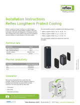
6.35 x 0.8 FAST ON
Terminal
4 x Ø 5.3 Holes on Ø 172
Ø 162.5 max.
Ø 139 max.
Ø 146 max.
68.5 max.
8
+
Red dot
Ø 187.5 max.
(on angles)
Ø 25.4
76.2
Comp. driver
push holder
65
max
Locating hole Ø 6.5
1520
■
1530
6.5” Coaxial Midrange Drivers
■
1” Entry Horn
1520 1530
TYPICAL CHARACTERISTICS
Rated impedance Z 8 16 Ω
Reference efficiency (1 W@1 m) - 97 97 dB SPL
Usable frequency range
1
- 400–5000 400–5000 Hz
Power handling capacity
2
(AES) - 250 250 W
Max Sound Pressure Level
3
SPL
max
118 118 dB SPL
Min. impedance modulus Z
min
6.2 @ 750Hz 12.0 @ 700Hz Ω
Voice-coil inductance
4
@ 1 kHz L
e1k
0.55 1.08 mH
@ 10 kHz L
e10k
0.31 0.62 mH
Bl product Bl 11.0 15.8 N/A
Moving mass M
ms
0.0105 0.0105 Kg
THIELE-SMALL PARAMETERS : TYPICAL (QC LIMITS)
Resonance frequency
5
F
s
130 (±25) 130 (±25) Hz
DC resistance
6
R
e
5.5 (±0.5) 10.6 (±1.1) Ω
Mechanical quality factor Q
ms
4.0 4.0 1
Electrical quality factor Q
es
0.38 0.35 1
Total quality factor Q
ts
0.35 0.33 1
Mechanical suspension compliance C
ms
145 145 10
-6
m/N
Effective piston area S
d
0.0123 0.0123 m
2
Equivalent C
as
air load V
as
0.0035 0.0035 m
3
Max. linear excursion X
max
±1.0 ±1.0 mm
Linear displacement volume V
d
0.0123 0.0123 10
-3
m
3
Half-space efficiency 1.9 2.0 %
Unity load volume V
as
Q
ts
2
0.41 0.36 10
-3
m
3
ABSOLUTE MAXIMUM RATINGS
Short term max. input voltage
7
V
max
90 125 V
Max. excursion before damage X
dam
4.0 4.0 mm
Ambient operating temperature –10 to +50 °C
Storage temperature
8
–20 to +70 °C
Environmental conditions
9
Outdoor
✚
APPLICATION INFORMATION
Air volume occupied by the driver
10
0.64 0.64 10
-3
m
3
Speaker net mass 2.6 2.6 Kg
Recommended reflex box V
b
/F
b
3L / sealed L / Hz
Electrical polarity A positive voltage applied on the red terminal
produces forward cone motion.
SPECIFICATION NOTES
Note 1 : Allowing for energy response, excursion
capability, Power spectrum, and -3dB low
freq. roll-off for standard reflex tuning.
Note 2 : Established at 20°C ambient temp, according to
AES2-1984 standard using IEC268-1 simulated
programme signal and a 3 liter sealed test enclosure
with a 2nd order high-pass filter @ 800Hz.
Note 3: Established at 1m on axis of the loudspeaker mounted
in test enclosure, when driven at full AES Power
Handling Capacity, including 3dB of thermal
compression loss.
Note 4 : Measured at 20 mA in free air.
Note 5: Measured at 20 mA and 20°C ambient temp.
in free air conditions, after full run and rest.
Note 6 : Measured at 20°C ambient temp.
QC limits are ±10%
Note 7: Stated in RMS voltage according to IEC 268-5.
Note 8 : Includes shipping conditions.
The lower limit prevents from demagnetization.
Note 9: Our products are classified in three categories :
Indoor, Outdoor, and Outdoor
✚
for permanent
outdoor use or severe conditions.
Note 10 : Calculated for front mounting on to a 18 mm thick
board.
PHYSICAL CHARACTERISTICS
PHL Audio S.A. provides these specifications as representative of current production after conditioning. Because of our continuous research, they are subject to change without notice.
461, rue des chênes ■ Z.A
77590 CHARTRETTES
FRANCE
Tél : 33 01 64 81 29 80
Fax : 33 01 60 69 10 28
e-mail : [email protected]
http: //www.phlaudio.com
/