Supermicro SUPERSERVER 6011H User manual
- Category
- Server barebones
- Type
- User manual

®
SUPERSERVER 6011H
USER’S MANUAL
1.0c
SUPER

The information in this User’s Manual has been carefully reviewed and is believed to be
accurate. The vendor assumes no responsibility for any inaccuracies that may be
contained in this document, makes no commitment to update or to keep current the
information in this manual, or to notify any person or organization of the updates.
Please
Note: For the most up-to-date version of this manual, please see our
web site at www.supermicro.com.
SUPERMICRO COMPUTER reserves the right to make changes to the product described in
this manual at any time and without notice. This product, including software, if any, and
documentation may not, in whole or in part, be copied, photocopied, reproduced, translated
or reduced to any medium or machine without prior written consent.
IN NO EVENT WILL SUPERMICRO COMPUTER BE LIABLE FOR DIRECT, INDIRECT,
SPECIAL, INCIDENTAL, SPECULATIVE OR CONSEQUENTIAL DAMAGES ARISING FROM
THE USE OR INABILITY TO USE THIS PRODUCT OR DOCUMENTATION, EVEN IF
ADVISED OF THE POSSIBILITY OF SUCH DAMAGES. IN PARTICULAR, THE VENDOR
SHALL NOT HAVE LIABILITY FOR ANY HARDWARE, SOFTWARE, OR DATA STORED
OR USED WITH THE PRODUCT, INCLUDING THE COSTS OF REPAIRING, REPLACING,
INTEGRATING, INSTALLING OR RECOVERING SUCH HARDWARE, SOFTWARE, OR
DATA.
Any disputes arising between manufacturer and customer shall be governed by the laws of
Santa Clara County in the State of California, USA. The State of California, County of
Santa Clara shall be the exclusive venue for the resolution of any such disputes.
Supermicro's total liability for all claims will not exceed the price paid for the hardware
product.
Unless you request and receive written permission from SUPER MICRO COMPUTER, you
may not copy any part of this document.
Information in this document is subject to change without notice. Other products and
companies referred to herein are trademarks or registered trademarks of their respective
companies or mark holders.
Copyright © 2003 by SUPER MICRO COMPUTER INC.
All rights reserved.
Printed in the United States of America.

Preface
About This Manual
This manual is written for professional system integrators and PC techni-
cians. It provides information for the installation and use of the Super-
Server 6011H. Installation and maintainance should be performed by expe-
rienced technicians only.
The SuperServer 6011H is a high-end dual processor 1U rackmount server
based on the SC810 1U rackmount server chassis and the P3TDER+, a dual
processor motherboard that supports single or dual Intel Pentium
®
III FCPGA
500 MHz-1.40 GHz processors at front bus speeds of 133 and 100 MHz
and up to 4 GB SDRAM main memory.
Manual Organization
Chapter 1: Introduction
The first chapter provides a checklist of the main components included with
the server system and describes the main features of the SUPER P3TDER+
mainboard and the SC810 chassis, which make up the SuperServer 6011H.
Chapter 2: Server Installation
This chapter describes the steps necessary to install the SuperServer
6011H into a rack and check out the server configuration prior to powering
up the system. If your server was ordered without processor and memory
components, this chapter will refer you to the appropriate sections of the
manual for their installation.
Chapter 3: System Interface
Refer here for details on the system interface, which includes the functions
and information provided by the control panel on the chassis as well as
other LEDs located throughout the system.
iii
Preface

SUPERSERVER 6011H User's Manual
iv
Chapter 4: System Safety
You should thoroughly familiarize yourself with this chapter for a general
overview of safety precautions that should be followed when installing and
servicing the SuperServer 6011H.
Chapter 5: Advanced Motherboard Setup
Chapter 5 provides detailed information on the P3TDER+ motherboard, in-
cluding the locations and functions of connections, headers, jumpers, DIP
switches and IRQs. Refer to this chapter when adding or removing proces-
sors or main memory and when reconfiguring the motherboard.
Chapter 6: Advanced Chassis Setup
Refer to Chapter 6 for detailed information on the SC810 1U rackmount
server chassis. You should follow the procedures given in this chapter
when installing, removing or reconfiguring SCSI or peripheral drives and
when replacing system power supply units and cooling fans.
Chapter 7: BIOS
The BIOS chapter includes an introduction to BIOS and provides detailed
information on running the CMOS Setup Utility.
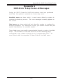
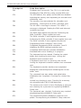
Appendix A: BIOS Error Beep Codes and Messages
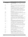
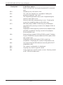
Appendix B: POST Diagnostic Error Codes
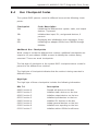
Appendix C: System Specifications

v
Preface
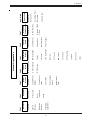
Manual Organization
Introduction
Chp1
Installation System
Interface
System
Safety
Motherboard
Details
Chassis
Details
BIOS and
Setup Routine
Chp3Chp2
Chp5
Chp4
Chp6
Appendices
Overview
Chassis
Features
Mainboard
Features
Contacting
Supermicro
Overview
Precautions
Rack
Installation
Setup
Overview
Control Panel
Buttons
Control Panel
LEDs
SCSI LEDs
Power Supply
Switch
Motherboard
LED
Static Safety
MB Installation
Cables
I/O Ports
CPU Installation
Memory
PCI Cards
MB Layout
Connectors
DIP Switches
Jumpers
Drive Conn.
IRQs
Static Safety
Control Panel
System Fans
Drive Bay Inst.
Power Supply
Chp7
App. A/B/C
Introduction
BIOS Features
Running CMOS
Setup
Electrical Safety
General Safety
ESD Safety
BIOS Error
Beep Codes
Post Diag. Error
Messages
System Specs

SUPERSERVER 6011H User's Manual
vi
Table of Contents
Preface
About This Manual ...................................................................................................... iii
Manual Organization ................................................................................................... iii
Manual Organization (Chart) ..................................................................................... v
Chapter 1: Introduction to the SuperServer 6011H
1-1 Overview......................................................................................................... 1-1
1-2 Server Chassis Features.............................................................................. 1-2
1-3 Mainboard Features ....................................................................................... 1-4
1-4 Contacting Supermicro .................................................................................. 1-6
Chapter 2: Server Installation
2-1 Overview......................................................................................................... 2-1
2-2 Unpacking the SuperServer 6011H............................................................. 2-1
2-3 Preparing for Setup ....................................................................................... 2-1
Choosing a Setup Location.................................................................... 2-2
Rack Precautions ..................................................................................... 2-2
Server Precautions.................................................................................. 2-2
2-4 Installing the SuperServer 6011H into a Rack .......................................... 2-3
Identifying the Sections of the Rack Rails.......................................... 2-3
Installing the Chassis Rails ..................................................................... 2-4
Installing the Rack Rails .......................................................................... 2-4
Installing the Server into the Rack ........................................................ 2-5
Installing the Server into a Telco Rack ................................................ 2-6
2-5 Checking the Motherboard Setup ................................................................ 2-7
2-6 Checking the Drive Bay Setup..................................................................... 2-9
2-7 Supplying Power to the System ................................................................ 2-10
Chapter 3: System Interface
3-1 Overview......................................................................................................... 3-1
3-2 Control Panel Buttons .................................................................................... 3-1
Reset.......................................................................................................... 3-1
Power ........................................................................................................ 3-1
3-3 Control Panel LEDs ........................................................................................ 3-2
Overheat ................................................................................................... 3-2
NIC1/2 ........................................................................................................ 3-2
HDD ............................................................................................................ 3-2

Power ........................................................................................................ 3-3
3-4 SCSI Drive Carrier LEDs ............................................................................... 3-3
3-5 Power Supply Switch.................................................................................... 3-3
3-6 Motherboard LED ............................................................................................ 3-3
Chapter 4: System Safety
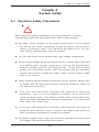
4-1 Electrical Safety Precautions ........................................................................ 4-1
4-2 General Safety Precautions .......................................................................... 4-2
4-3 ESD Precautions .............................................................................................. 4-3
4-4 Operating Precautions .................................................................................... 4-4
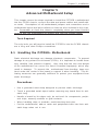
Chapter 5: Advanced Motherboard Setup
5-1 Handling the P3TDER+ Motherboard ............................................................ 5-1
5-2 Motherboard Installation ................................................................................. 5-2
5-3 Connecting Cables .......................................................................................... 5-3
Connecting Data Cables .......................................................................... 5-3
Connecting Power Cables....................................................................... 5-3
Connecting the Control Panel ................................................................. 5-4
5-4 I/O Ports ............................................................................................................ 5-5
5-5 Installing Processors ...................................................................................... 5-5
5-6 Installing Memory ............................................................................................. 5-8
5-7 Adding PCI Cards ............................................................................................ 5-9
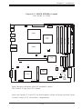
SUPER P3TDER+ Layout ....................................................................... 5-11
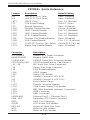
SUPER P3TDER+ Quick Reference ...................................................... 5-12
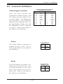
5-8 Connector Definitions ................................................................................... 5-13
Power Supply Connector ..................................................................... 5-13
Power .......................................................................................................5-13
Reset......................................................................................................... 5-13
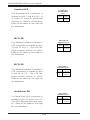
Overheat LED .......................................................................................... 5-14
NIC 1 LED ................................................................................................ 5-14
NIC 2 LED ................................................................................................ 5-14
Hard Drive LED ....................................................................................... 5-14
Power LED............................................................................................... 5-15
Chassis Intrusion .................................................................................... 5-15
Extra USB Connection ........................................................................... 5-15
Fan Headers............................................................................................ 5-15
Serial Ports .............................................................................................. 5-16
ATX PS/2 Keyboard & Mouse Ports.................................................... 5-16
Universal Serial Bus (USB)................................................................... 5-16
Wake-On-LAN ......................................................................................... 5-16
vii
Table of Contents

SUPERSERVER 6011H User's Manual
viii
SLED1 (SCSI LED) Indicator.................................................................. 5-17
Power Supply Fail Header .................................................................... 5-17
IPMB .......................................................................................................... 5-17
SMB ........................................................................................................... 5-17
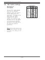
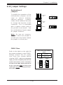
5-9 DIP Switch Settings ...................................................................................... 5-18
DIP Switch 1: Processor Speed ......................................................... 5-18
5-10 Jumper Settings ............................................................................................. 5-19
Explanation of Jumpers ......................................................................... 5-19
CMOS Clear.............................................................................................. 5-19
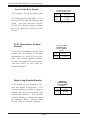
Front Side Bus Speed ........................................................................... 5-20
SCSI Termination Enable/Disable.......................................................... 5-20
Watch Dog Enable/Disable ....................................................................5-20
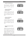
Speaker Enable/Disable ......................................................................... 5-21
Onboard LAN 1 (NIC) Enable/Disable.................................................. 5-21
Onboard LAN 2 (NIC) Enable/Disable.................................................. 5-21
Spread Spectrum Enable/Disable ......................................................... 5-21
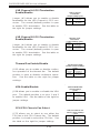
LVD Channel A SCSI Termination Enable/Disable............................. 5-22
LVD Channel B SCSI Termination Enable/Disable ............................. 5-22
Thermal Fan Enable/Disable.................................................................. 5-22
VGA Enable/Disable ............................................................................... 5-22
CPU/CPU Chassis Fan Select ............................................................... 5-22
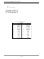
5-11 Floppy/Hard Drive and SCSI Connections................................................. 5-23
Floppy Connector................................................................................... 5-23
IDE Connectors ...................................................................................... 5-24
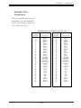
Ultra160 SCSI Connectors..................................................................... 5-25
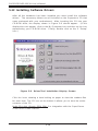
5-12 Installing Software Dirvers.......................................................................... 5-26
Chapter 6: Advanced Chassis Setup
6-1 Static-Sensitive Devices ................................................................................ 6-1
6-2 Control Panel .................................................................................................... 6-2
6-3 System Fans .................................................................................................... 6-3
System Fan Failure.................................................................................. 6-3
Replacing System Cooling Fans............................................................ 6-3
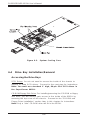
6-4 Drive Bay Installation/Removal ...................................................................... 6-4
Accessing the Drive Bays ..................................................................... 6-4
SCSI Drive Installation............................................................................. 6-5
IDE Drive Installation................................................................................ 6-7
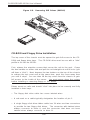
CD-ROM and Floppy Drive Installation ................................................. 6-8
6-5 Power Supply .................................................................................................. 6-9

Table of Contents
ix
Power Supply Failure ............................................................................. 6-9
Replacing the Power Supply ................................................................. 6-9
Chapter 7: BIOS
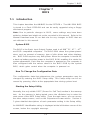
7-1 Introduction....................................................................................................... 7-1
7-2 BIOS Features.................................................................................................. 7-2
7-3 Running Setup.................................................................................................. 7-2
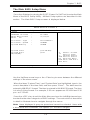
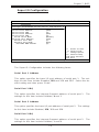
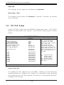
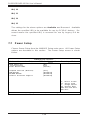
The Main BIOS Setup Menu .................................................................... 7-3
7-4 Advanced BIOS Setup.................................................................................... 7-4
7-5 Chipset Setup................................................................................................. 7-16
7-6 PCI PnP Setup ................................................................................................ 7-18
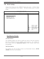
7-7 Power Setup .................................................................................................. 7-20
7-8 Boot Setup......................................................................................................7-22
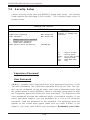
7-9 Security Setup ............................................................................................... 7-24
7-10 Exit Setup ....................................................................................................... 7-26
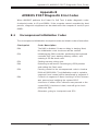
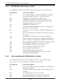
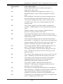
Appendices:
Appendix A: BIOS Error Beep Codes & Messages ........................................... A-1
Appendix B: AMIBIOS POST Diagnostic Error Codes.........................................B-1
Appendix C: System Specifications ......................................................................C-1

SUPERSERVER 6011H User's Manual
x
Notes

Chapter 1
Introduction to the SuperServer 6011H
1-1 Overview
The Supermicro SuperServer 6011H is a high-end dual processor, 1U
rackmount server that features some of the most advanced technology
currently available. The SuperServer 6011H is comprised of two main sub-
systems: the SC810 1U rackmount chassis and the P3TDER+, a 370-pin
Pentium III Tualatin dual processor mainboard. Please refer to our web site
for information on operating systems that have been certified for use with
the SuperServer 6011H. (www.supermicro.com)
In addition to the mainboard and chassis, various hardware components
may have been included with your SuperServer 6011H, as listed below:
! Up to two (2) 370-pin Pentium III Tualatin processors*
! Two (2) CPU heat sinks* (SNK-023)
! Up to 4 GB ECC registered SDRAM main memory*
! One (1) 1.44" floppy drive
! One (1) slim CD-ROM drive
! One (1) SCA SCSI backplane**
! Two (2) SCA 1-inch high SCSI drive carriers**
! SCSI Accessories**
One (1) internal 68-pin Ultra160 SCSI cable for SCA SCSI backplane
One (1) set of SCSI driver diskettes
One (1) SCSI manual
! Rackmount hardware (with screws):
Two (2) rack rail assemblies
Six (6) brackets for mounting the rack rails to a rack/telco rack
! One (1) CD-ROM containing drivers and utilities:
Intel LANDesk Client Manager
Chapter 1: Introduction
1-1

SUPERSERVER 6011H User's Manual
1-2
1-2 Server Chassis Features
The SuperServer 6011H is a high-end, scaleable 1U rackmount server plat-
form designed with today's most state-of-the-art features. The following is
a general outline of the main features of the SC810, a 1U chassis optimized
for the use of riser cards.
System Power
When configured as a SuperServer 6011H, the SC810 chassis includes a
250W power supply.
SCSI Subsystem
The SCSI subsystem supports two 80-pin SCA Ultra160 SCSI hard drives.
(Any standard 1" drives are supported. SCA = Single Connection Attach-
ment.) The SCSI drives are connected to an SCA backplane that provides
power, bus termination and configuration settings. The SCSI drives are
also hot-swap units.
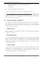
Control Panel
The SC810's control panel provides important system monitoring and control
information. LEDs indicate power on, network activity, hard disk drive ac-
tivity and system overheat conditions. The control panel also includes a
main power button and a system reset button.
ATI Rage XL 8MB PCI graphics controller driver
LAN driver
SCSI driver
! SuperServer 6011H User's Manual
* Type and number depends upon the configuration ordered.
** SCSI components are not included on the 6011HI model. All information
in this manual relating to the SCSI subsystem and SCSI drives do not
apply to the 6011HI. For information on installing/removing IDE drives on
the 6011HI, refer to Section 6-4.

1-3
Chapter 1: Introduction
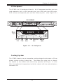
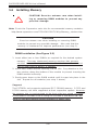
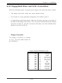
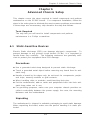
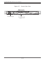
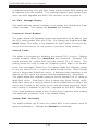
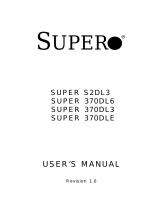
IO Backpanel
The SC810 is a 1U rackmount chassis. Its IO backpanel provides one riser
card expansion slot, a VGA (monitor) port, one COM port, two USB ports,
PS/2 mouse and keyboard ports and two Ethernet ports. (See Figure 1-1.)
Cooling System
The SC810 chassis has an innovative cooling design that includes a 10-cm
blower system cooling (intake) fan. The blower fan plugs into a chassis
fan header on the mother and continuously operates at full rpm. If a fan
fails, the ambient air temperature inside the chassis will rise and activate an
overheat LED.
Figure 1-1. IO Backpanel

SUPERSERVER 6011H User's Manual
1-4
1-3 Mainboard Features
At the heart of the SuperServer 6011H lies the P3TDER+, a dual processor
motherboard designed to provide high performance. The following are the
main features of the P3TDER+.
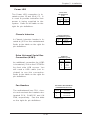
Chipset
The P3TDER+ is based on ServerWorks ServerSet
TM
III HE-SL chipset, which
is a high-performance core logic chipset that consists of a North Bridge and
a South Bridge.
The North Bridge includes an integrated main memory subsystem and a dual
channel PCI bus that bridges the processor bus to a 64-bit PCI bus and a
32-bit PCI bus. The North Bridge also packs and unpacks data for PCI
accesses, which reserves more processor bandwidth for multiprocessor
motherboards.
The South Bridge provides various integrated functions, including the PCI to
ISA bridge and support for UDMA33, security (passwords and system pro-
tection), Plug & Play, USBs, power management, interrupt controllers and
the SMBus.
Processors
The P3TDER+ supports single or dual Pentium III Tualatin 500 MHz-1.40 GHz
processors at either a 100 or 133 MHz FSB. Please refer to the support
section of our web site for a complete listing of supported processors
(http://www.supermicro.com/TechSupport.htm).
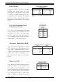
Memory
The P3TDER+ has 4 DIMM slots that can support up to 4 GB of ECC regis-
tered PC133 and PC100 SDRAM. Module sizes of 128MB, 256MB, 512MB
and 1 GB may be used to populate the 25 degree DIMM slots.
Onboard SCSI
Onboard SCSI is provided with an Adaptec AIC-7899W SCSI controller chip,
which supports dual channel, Ultra160 (320 optional) SCSI at a burst
throughput rate of 160 MB/sec. The P3TDER+ provides two SCSI ports.

1-5
Chapter 1: Introduction
PCI Expansion Slots
The P3TDER+ has one 64-bit 66/33 MHz PCI slot.
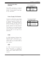
ATI Graphics Controller
The P3TDER+ includes an onboard ATI Rage XL graphics controller. The
Rage XL fully supports sideband addressing. This graphics package pro-
vides a bandwidth of up to 512 MB/sec over a 32-bit graphics memory bus.
Onboard Controllers/Ports
One floppy drive controller and two onboard IDE controllers support one up
to four hard drives or ATAPI devices. Onboard I/O ports include one COM
port, two USB ports, PS/2 mouse and keyboard ports, a video (monitor) port
and two 10/100 MB Intel 82559 Ethernet (NIC) ports. The P3TDER also
includes an onboard ATI Rage XL graphics controller (see above).
Other Features
Other onboard features that promote system health include five voltage
monitors, two CPU temperature sensors, four fan speed sensors, a chas-
sis intrusion header, auto-switching voltage regulators, chassis and CPU
overheat sensors, virus protection and BIOS rescue.

SUPERSERVER 6011H User's Manual
1-6
1-4 Contacting Supermicro
Headquarters
Address: SuperMicro Computer, Inc.
980 Rock Ave.
San Jose, CA 95131 U.S.A.
Tel: +1 (408) 503-8000
Fax: +1 (408) 503-8008
Email: [email protected] (General Information)
[email protected] (Technical Support)
Web Site: www.supermicro.com
Europe
Address: SuperMicro Computer B.V.
Het Sterrenbeeld 28, 5215 ML
's-Hertogenbosch, The Netherlands
Tel: +31 (0) 73-6400390
Fax: +31 (0) 73-6416525
Email: [email protected] (General Information)
[email protected] (Technical Support)
[email protected] (Customer Support)
Asia-Pacific
Address: SuperMicro, Taiwan
D5, 4F, No. 16 Chien-Ba Road
Chung-Ho 235, Taipei Hsien, Taiwan, R.O.C.
Tel: +886-(2) 8226-3990
Fax: +886-(2) 8226-3991
Web Site: www.supermicro.com.tw
Technical Support:
Email: su[email protected]
Tel: 886-2-8228-1366, ext.132 or 139

Chapter 2: Server Installation
2-1
Chapter 2
Server Installation
2-1 Overview
This chapter provides a quick setup checklist to get your SuperServer
6011H up and running. Following these steps in the order given should
enable you to have the system operational in a minimum amount of time.
This quick setup assumes that your SuperServer 6011H system has come
to you with the processors and memory preinstalled. If your system is not
already fully integrated with a motherboard, processors, system memory
etc., please turn to the chapter or section noted in each step for details on
installing specific components.
2-2 Unpacking the SuperServer 6011H
You should inspect the box the SuperServer 6011H was shipped in and
note if it was damaged in any way. If the server itself shows damage you
should file a damage claim with the carrier who delivered it.
Decide on a suitable location for the rack unit that will hold the SuperServer
6011H. It should be situated in a clean, dust-free area that is well venti-
lated. Avoid areas where heat, electrical noise and electromagnetic fields
are generated. You will also need it placed near a grounded power outlet.
Read the Rack and Server Precautions in the next section.
2-3 Preparing for Setup
The box the SuperServer 6011H was shipped in should include two sets of
rail assemblies, two rail mounting brackets and the mounting screws you
will need to install the system into the rack. Follow the steps in the order
given to complete the installation process in a minimum amount of time.
Please read this section in its entirety before you begin the installation
procedure outlined in the sections that follow.

2-2
SUPERSERVER 6011H User's Manual
Choosing a Setup Location:
- Leave enough clearance in front of the rack to enable you to open
the front door completely (~25 inches).
- Leave approximately 30 inches of clearance in the back of the rack
to allow for sufficient airflow and ease in servicing.
Rack Precautions
- Ensure that the leveling jacks on the bottom of the rack are fully
extended to the floor with the full weight of the rack resting on them.
- In single rack installation, stabilizers should be attached to the rack.
- In multiple rack installations, the racks should be coupled together.
- Always make sure the rack is stable before extending a component
from the rack.
- You should extend only one component at a time - extending two or
more simultaneously may cause the rack to become unstable.
Server Precautions
- Review the electrical and general safety precautions in Chapter 4.
- Determine the placement of each component in the rack before you
install the rails.
- Install the heaviest server components on the bottom of the rack
first, and then work up.
- Use a regulating uninterruptible power supply (UPS) to protect the
server from power surges, voltage spikes and to keep your
system operating in case of a power failure.
- Allow the hot plug SCSI drives and power supply units to cool before
touching them.
- Always keep the rack's front door and all panels and components on
the servers closed when not servicing to maintain proper cooling.
!
!
Warnings and Precautions!

Chapter 2: Server Installation
2-3
2-4 Installing the SuperServer 6011H into a Rack
This section provides information on installing the SuperServer 6011H into
a rack unit. If the 6011H has already been mounted into a rack, you can
skip ahead to Sections 2-5 and 2-6. There are a variety of rack units on
the market, which may mean the assembly procedure will differ slightly.
The following is a general guideline for installing the 6011H into a rack with
the rack rails provided. You should also refer to the installation instructions
that came with the rack unit you are using.
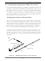
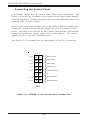
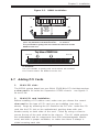
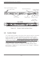
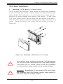
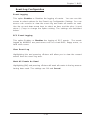
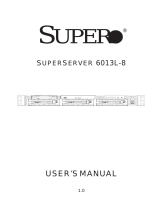
Identifying the Sections of the Rack Rails
You should have received two rack rail assemblies with the SuperServer
6011H. Each of these assemblies consist of two sections: an inner fixed
chassis rail that secures to the 6011H (A) and an outer fixed rack rail that
secures directly to the rack itself (B). A sliding rail guide sandwiched
between the two should remain attached to the fixed rack rail. (See Figure
2-1.) The A and B rails must be detached from each other to install.
To remove the fixed chassis rail (A), pull it out as far as possible - you
should hear a "click" sound as a locking tab emerges from inside the rail
assembly and locks the inner rail. Then depress the locking tab to pull the
inner rail completely out. Do this for both the left and right side rack rail
assemblies.
Figure 2-1. Identifying the Sections of the Rack Rails
Mounting Holes
A
Locking Tab
B

2-4
SUPERSERVER 6011H User's Manual
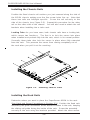
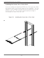
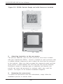
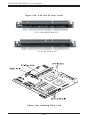
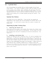
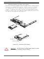
Installing the Chassis Rails
Position the fixed chassis rail sections you just removed along the side of
the 6011H chassis making sure the five screw holes line up. Note that
these two rails are left/right specific. Screw the rail securely to the
side of the chassis (see Figure 2-2). Repeat this procedure for the other
rail on the other side of the chassis. You will also need to attach the rail
brackets when installing into a telco rack.
Locking Tabs: As you have seen, both chassis rails have a locking tab,
which serves two functions. The first is to lock the server into place
when installed and pushed fully into the rack, which is its normal position.
Secondly, these tabs also lock the server in place when fully extended
from the rack. This prevents the server from coming completely out of
the rack when you pull it out for servicing.
Figure 2-2. Installing Chassis Rails
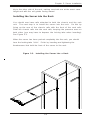
Installing the Rack Rails
Determine where you want to place the SuperServer 6011H in the rack.
(See Rack and Server Precautions in Section 2-3.) Position the fixed rack
rail/sliding rail guide assemblies at the desired location in the rack, keeping
the sliding rail guide facing the inside of the rack. Screw the assembly
securely to the rack using the brackets provided. Attach the other assem-
Page is loading ...
Page is loading ...
Page is loading ...
Page is loading ...
Page is loading ...
Page is loading ...
Page is loading ...
Page is loading ...
Page is loading ...
Page is loading ...
Page is loading ...
Page is loading ...
Page is loading ...
Page is loading ...
Page is loading ...
Page is loading ...
Page is loading ...
Page is loading ...
Page is loading ...
Page is loading ...
Page is loading ...
Page is loading ...
Page is loading ...
Page is loading ...
Page is loading ...
Page is loading ...
Page is loading ...
Page is loading ...
Page is loading ...
Page is loading ...
Page is loading ...
Page is loading ...
Page is loading ...
Page is loading ...
Page is loading ...
Page is loading ...
Page is loading ...
Page is loading ...
Page is loading ...
Page is loading ...
Page is loading ...
Page is loading ...
Page is loading ...
Page is loading ...
Page is loading ...
Page is loading ...
Page is loading ...
Page is loading ...
Page is loading ...
Page is loading ...
Page is loading ...
Page is loading ...
Page is loading ...
Page is loading ...
Page is loading ...
Page is loading ...
Page is loading ...
Page is loading ...
Page is loading ...
Page is loading ...
Page is loading ...
Page is loading ...
Page is loading ...
Page is loading ...
Page is loading ...
Page is loading ...
Page is loading ...
Page is loading ...
Page is loading ...
Page is loading ...
Page is loading ...
Page is loading ...
Page is loading ...
Page is loading ...
Page is loading ...
Page is loading ...
Page is loading ...
Page is loading ...
Page is loading ...
Page is loading ...
Page is loading ...
Page is loading ...
Page is loading ...
Page is loading ...
Page is loading ...
Page is loading ...
Page is loading ...
Page is loading ...
Page is loading ...
Page is loading ...
Page is loading ...
Page is loading ...
-
 1
1
-
 2
2
-
 3
3
-
 4
4
-
 5
5
-
 6
6
-
 7
7
-
 8
8
-
 9
9
-
 10
10
-
 11
11
-
 12
12
-
 13
13
-
 14
14
-
 15
15
-
 16
16
-
 17
17
-
 18
18
-
 19
19
-
 20
20
-
 21
21
-
 22
22
-
 23
23
-
 24
24
-
 25
25
-
 26
26
-
 27
27
-
 28
28
-
 29
29
-
 30
30
-
 31
31
-
 32
32
-
 33
33
-
 34
34
-
 35
35
-
 36
36
-
 37
37
-
 38
38
-
 39
39
-
 40
40
-
 41
41
-
 42
42
-
 43
43
-
 44
44
-
 45
45
-
 46
46
-
 47
47
-
 48
48
-
 49
49
-
 50
50
-
 51
51
-
 52
52
-
 53
53
-
 54
54
-
 55
55
-
 56
56
-
 57
57
-
 58
58
-
 59
59
-
 60
60
-
 61
61
-
 62
62
-
 63
63
-
 64
64
-
 65
65
-
 66
66
-
 67
67
-
 68
68
-
 69
69
-
 70
70
-
 71
71
-
 72
72
-
 73
73
-
 74
74
-
 75
75
-
 76
76
-
 77
77
-
 78
78
-
 79
79
-
 80
80
-
 81
81
-
 82
82
-
 83
83
-
 84
84
-
 85
85
-
 86
86
-
 87
87
-
 88
88
-
 89
89
-
 90
90
-
 91
91
-
 92
92
-
 93
93
-
 94
94
-
 95
95
-
 96
96
-
 97
97
-
 98
98
-
 99
99
-
 100
100
-
 101
101
-
 102
102
-
 103
103
-
 104
104
-
 105
105
-
 106
106
-
 107
107
-
 108
108
-
 109
109
-
 110
110
-
 111
111
-
 112
112


Supermicro SUPERSERVER 6011H User manual
- Category
- Server barebones
- Type
- User manual
Ask a question and I''ll find the answer in the document
Finding information in a document is now easier with AI
Related papers
-
Supermicro SUPERSERVER 6011L User manual
-
-
-
Supermicro SuperServer 6021i, Beige User manual
-
Supermicro SUPERSERVER 6022L-6 User manual
-
-
-
-
-
Other documents
-
Gigabyte 6BXU User manual
-
-
 Audavi Ultra Wide SCSI HardTape Bay Quick start guide
-
-
HP Motherboard User guide
-
SUPER MICRO Computer SUPER P3TDDR User manual
-
 Supero SUPER 370DLE User manual
-
American Megatrends Olympus II S821 Motherboard User guide
-
 Supero SUPERSERVER 6013L-8 User manual
-


