Page is loading ...

Owners
Manual
FOR POTABLEWATER
HEATING ONLY
NOT SUITABLEFOR
SPACEHEATING
Model No.
153.318031 27 GaL
153.318131 40 Gal.
LISTED
Caution:
Read and Follow
All Safety Rules and
Operating Instructions
Before First Use of
This Product.
Save this Manual for Future Reference.
THE ECONOMIZER TM6
TABLE TOP ELECTRIC
WATER HEATER
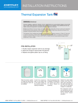
• Safety Instructions
• Installation
• Operation
• Care and Maintenance
• Troubleshooting
• Parts List
GAMA certification applies to all residential electric water heaters with
capacitiesof 20 to 120 Gallons. Inputrating of 12Kw or lessat avoltage
no greater than 250
_WARNING
READ THE GENERAL SAFETY SECTION BEGINNING ON INSIDE COVER
AND THEN THIS ENTIRE HANUAL BEFORE INSTALLING OR OPERAT-
ING THIS WATER HEATER.
Sears, Roebuck and Co., Hoffman Estates, IL 60179 U.S.A.
Printed in the U.S.A. 1203 www.sears.com Part No. 184733-000

Safety Precautions
AWARNING J
Improper installation,adjustment, alteration, service or
maintenancecancauseDEATH, SERIOUSBODILY INJURY,J
OR PROPERTY DAMAGE. Refer to this manualfor assis-
tanceor consult your localSearsServiceCenter for further
information.
AWARNING
At the time of manufacture thiswater heater wasprovidedwith
a combination temperature-pressures relief valve certified by a
nationally recognized testing laboratory that maintainsperiodic
inspection of production of listed equipment or materials, as
meeting the requirements for Relief Valvesand Automatic Gas
Shutoff Devicesfor Hot Water SupplySystems,andthe current
edition ofANSI Z21.22, CSA 4.4 and the coderequirements of
ASME. If replaced, the valve must meet the requirements of
local codes, but not lessthan a combination temperature and
pressurerelief valve certified as meeting the requirements for
ReliefValvesand Automatic Gas Shutoff Devicesfor Hot Water
SupplySystems, ANSI Z21.22, CSA 4.4 by a nationally recog-
nized testing laboratory that maintains periodic inspection of
productionof listedequipment or materials.
The valve must be marked with a maximum setpressurenot to
exceed the marked hydrostatic working pressureof the water
heater (150 Ibs./sq.in.) and a dischargecapacity not lessthan
the water heater input rate asshownonthe model rating plate.
(Electric heaters - watts divided by 1000x 3412 equal BTU/Hr.
rate.)
Your local jurisdictionalauthority, while mandating the use of a
temperature-pressure relief valvecomplyingwith ANSI Z21.22,
CSA 4.4 and ASME, may require a valve model different from
the onefurnishedwith the water heater.
Compliance with such local requirements must be satisfied by
the installer or end user of the water heater with a locallypre-
scribedtemperature-pressure relief valve installed in the desig-
nated opening in the water heater in place of the factory fur-
nished valve.
For safeoperation of the water heater, the relief valvemust not
be removed from it'sdesignatedopeningor plugged.
The temperature-pressure relief valve must be installeddirectly
into the fitting of the water heater designated for the relief
valve. Positionthe valve downward and provide tubing so that
anydischargewill exit only within 6 inchesabove, or at any dis_
tance below the structural floor. Be certain that no contact is
made with any live electrical part. The dischargeopening must
not be blocked or reduced in size under any circumstances.
Excessivelength, over 30 feet, or useof more than four elbows
can cause restriction and reduce the discharge capacity of the
valve.
No valve or other obstruction is to be placed between the
relief valve and the tank. Do not connect tubing directly to
dischargedrain unlessa 6" air gap isprovided.To prevent bod-
ily injury, hazard to life, or property damage, the relief valve
must be allowed to discharge water in quantities should cir-
cumstances demand. If the discharge pipe isnot connected to
a drain or other suitable means, the water flow may cause
property damage.
The DischargePipe:
• Must not be smaller in size than the outlet pipe size of the
valve,or haveanyreducing couplingsor other restrictions.
• Must not be pluggedor blocked.
• Must be ofmaterial listedfor hot water distribution.
• Must be installedsoasto allowcomplete drainage of both the
temperature-pressure relief valve,and the dischargepipe.
• Mustterminate at an adequate drain.
• Must not haveanyvalvebetween the relief valveand tank.
AWARNING
HAZARD OF ELECTRICAL SHOCK! Before removing
any access panels or servicing the water heater, make I
sure the electrical supply to the water heater is turned
"OFF". Failure to do this could result in DEATH, SERI-
OUS BOD LY NJURY, OR PROPERTY DAMAGE.
AWARNING
HOTTER WATER CAN SCALD: Water heaters are
intended to produce hot water. Water heated to a temper-
ature which will satisfy space heating, clothes washing, dish
washing, and other sanitizing needs can scald and perma-
nently injure you upon contact. Some people are more like-
ly to be permanently injured by hot water than others.
These include the elderly, children, the infirm, or physical-
ly/mentally handicapped. If anyone using hot water in your
home fits into one of these groups or if there is a local code
or state law requiring a certain temperature water at the
hot water tap, then you must take special precautions. In
addition to using the lowest possible temperature setting
that satisfiesyour hot water needs, a means such as a mix-
ing valve, shall be used at the hot water taps used by these
people or at the water heater. Mixing valves are available at
plumbing supply or hardware stores. Follow manufacturers
instructions for installation of the valves. Before changing
the factory setting on the thermostat, read the
"Temperature Regulation" section in this manual.
AWARNING
WATER HEATERS EQUIPPED FOR ONE VOLTAGE
ONLY: This water heater is equipped for one type volt-
age only. Check the rating plate near the bottom access
panel for the correct voltage. DO NOT use this water
heater with any voltage other than the one shown on the
model rating plate. Failure to use the correct voltage can
cause problems which can result in DEATH, SERIOUS
BODILY INJURY, OR PROPERTY DAMAGE. If you have
any questions or doubts consult your electric company.
AWARNING
INSULATING JACKETS: When installing an external
water heater insulation jacket on an electric water heater:
a. DO NOT cover the temperature-pressure relief valve.
b. DO NOT put insulation over the access covers or any
access areas.
c. DO NOT remove operating instructions, and safety
related warning labels and materials affixed to the
water heater.
d. DO obtain new warning and instruction labels from
Sears for placement on the jacket directly over the
existing labels.
AWARNING
Do not usethis applianceif anypart of it hasbeen under I
water. An electrical short or malfunction could occur.
The water heater sboud be rap aced.
A CAUTION
WATER HEATERS EVENTUALLY LEAK: Installation of
the water heater must be accomplished in such a manner
that if the tank or any connections should leak, the flow of
water will not cause damage to the structure. When such
locations cannot be avoided, a suitable drain pan should be
installed under the water heater. Drain pans are available
at your local hardware store. Such a drain pan must be
piped to an adequate drain.
2

Table of Contents
Safety Precautions ............................................................................................................................................2
Table of Contents .............................................................................................................................................3
Customer Responsibilities ...................................................................................................................4
Product Spedfications ...............................................................................................................................4
Materials and Basic Tools Needed .....................................................................................5
Materials Needed ...................................................................................................................................................................... 5
Basic "lbols ................................................................................................................................................................................ 5
Installation Instructions ....................................................................................................................6-14
Removing the Old Water Heater. ............................................................................................................................................ N
Facts m Consider About the Location ..................................................................................................................................... .7
Facts m Consider About the Convertible Element ................................................................................................................... .7
Water Piping ............................................................................................................................................................................ .8
T&P Valve and Pipe Insulation ................................................................................................................................................ .8
"l_mperature-Nessure Relief Valve ............................................................................................................................................ _
Filling the Water Hearer .......................................................................................................................................................... 10
Converting the Element ................................................................................................................................................... 10-12
Wiring Diagram ..................................................................................................................................................................... 12
Wiring .................................................................................................................................................................................... 13
Installation Checklist .............................................................................................................................................................. 14
Service and Adjustment ..............................................................................................................15-19
_l_mperature Regulation .......................................................................................................................................................... 15
Thermostats ............................................................................................................................................................................ 15
_l_mperature Settings .............................................................................................................................................................. 15
Thermostat Adjustment .......................................................................................................................................................... 15
_lhnperature Pressure Relief Valve Operation .......................................................................................................................... 16
Draining ................................................................................................................................................................................. 16
Element Cleaning/Replacement ........................................................................................................................................ 16-19
Anode Rod Inspection ............................................................................................................................................................ 19
Drain Valve Washer Replacement ........................................................................................................................................... 19
Service .................................................................................................................................................................................... 19
Troubleshooting Guide .............................................................................................................. 20-23
Start Up Conditions .............................................................................................................................................................. 20
Thermal Expansion .............................................................................................................................................................. .20
Strange Sounds .................................................................................................................................................................... .20
Operational Conditions ..................................................................................................................................................... 21,22
Smelly Water ........................................................................................................................................................................ .21
"Air" In Hot Water Faucets ................................................................................................................................................. .21
Rumbling Noise ................................................................................................................................................................... .21
High "Ihnperature Shut Of}'System ................................................................................................................................. 21,22
Not Enough or No Hot Water ............................................................................................................................................. .22
Water Is *lbo Hot ................................................................................................................................................................. .22
Leakage Checkpoints ........................................................................................................................................................... .23
Parts Order List ............................................................................................................................................26,27
Warranty.. .....................................................................................................................................................................28
3

Customer Responsibilities
Thank You for purchasing a Sears water heater.
Properly installed and maintained, it should give you years of"
trouble free service. If you should decide that you want the new
water heater professionally installed by Sears contact the local
Sears Service Center or any Sears store. They will arrange for
prompt, quality installation by Sears authorized contractors.
Abbreviations Found In This Instruction Manual
U.L.-Underwriters Laboratories Inc., 333 Pfingsten Rd.,
Northbrook, IL 60062
NEC - National Electrical Code
ANSI -American National Standards Institute
• Read the "Safety Precautions" section of this manual first and
then the entire manual carefully, lfyou don't follow the safe-
ty rules, the water heater will not operate properly. It could
cause DEATH, SERIOUS BODILY INJURY AND/OR
PROPERTY DAMAGE.
This manual contains instructions for the installation, opera-
tion, and maintenance of this electric water heater. It also
contains warnings throughout the manual that you must
read and be aware of. Allwarnings and all instructions are
essential to the proper operation of the water heater and your
safety. Since we cannot put everything on the first few pages,
READ THIS ENTIRE MANUAL BEFORE ATTEMPT-
ING TO INSTALL OR OPERATE THE WATER
HEATER.
The installation must conform with the instructions in the
manual; electric company rules; and Local Codes, or in the
absence of Local Codes, with the current edition of the
National Electrical Code. This publication is available from
your local government or public library or electric company
or by writing Underwriters Laboratories, 333 Pfingsten Road,
Northbrook, IL 60062.
If after reading this manual you have any questions or do not
understand any portion of the instructions, call Sears Service
Center.
Carefully plan the place where you are going to put the water
heater. Correct electrical wiring and connections are very
important in preventing death from possible electrical shock
and fires.
Examine the location to ensure the water heater complies with
the "Facts to Consider About the Location" section.
For California installation this water heater must be braced,
anchored, or strapped to avoid falling or moving during an
earthquake. See instructions for correct installation proce-
dures. Instructions may be obtained from your local dealer,
wholesaler, public utilities or California Office of the State
Architect, 400 P Street, Sacramento, CA 95814.
• Massachusetts Code requires this water heater to be installed
in accordance with Massachusetts 248-CMR 2.00: State
Plumbing Code and 248-CMR 5.00.
Product Specifications
MODEL
NUMBER
153.318031
153.318131
TANK
CAPACITY
IN GALLONS
27
4O
DIMENSIONS IN INCHES
WIDTH DEPTH HEIGHT
21" 25" 36"
24" 25" 36"
RECOVERYRATE
GALS.PER HOUR
@90°E RISE
17.3
25.0
17.3
25.0
ELEMENT
WATTAGE
AT 240 VOLTS
3800
5500
3800
5500
MINIMUM
WIRE SIZE*
(GAUGE)
12
10
12
10
MAXIMUM FUSE
OR CIRCUIT
B_AKER
SIZE (AMPS)
20
30
20
30
*Wiring size based on standard 60°C. copper wire. If distance from fuse box to water heater is more than 90 feet, refer to your local electrical
code.
4

Materials and Basic Tools Needed
Materials Needed
_b simplify the installation Sears has available the installation
parts shown below. You may or may not need all of these materi-
als, depending on your type of installation.
WATER HEATER INSTALLA-
TION KIT WITH FLEXIBLE
CONNECTORS FOR 3/4" OR
I/2" THREADED OR SWEAT
COPPER PLUMBING
WATER HEATER HEAT TRAPS
HELP REDUCE HEAT LOSS
DUE TO THERMAL
SYPHONING
EXPANSION TANKS FOR THERMAL
EXPANSION CONDITIONS AVAILABLE IN
2 GALLON AND 5 GALLON CAPACITY
THROUGH LOCAL SEARS SERVICE CENTERS
Basic Tools
You may or may not need all of these tools, depending on your
type of installation. These tools can be purchased at your local
Sears store.
Pipe Wrench (2)
Screwdriver
6 Foot Tapeor FoldingRule
Garden Hose
Drill
Pipe Dope or Teflon Tape
6 FOOT TAPE
GARDEN HOSE
SLOT-HEAD SCREW DRIVER
j
PHILLIPS SCREWDRIVER
PIPE
WRENCH
PIPE DOPE (SQUEEZE TUBE) _
roll of teflon tape DRILL
(Use only on water connec-
tions)
ADDITIONAL TOOLS NEEDED
WHEN SWEAT SOLDERING
TubingCutters or Hacksaw
Propane Torch
Soft Solder
Solder Flux
Emery Cloth
Wire Brushes
HACKSAW
3/4" WIRE BRUSH
1/2" WIRE BRUSH
PROPANE TORCH
ROLL OF LEAD FREE
SOFT SOLDER
ROLL OF EMERY SOLDER TUBING
CLOTH FLUX CUTTER

Installation Instructions
Removing the Old Water
Heater
Q_hrn "OFF" electrical supply to the water heater.
Q'fhrn "OFF" the water supply to the water heater at the
water shutoff"valveor water meter.
Q a. you copper piping to water two
If have the
heater, the
copper water pipes can be cut with a hacksaw approxi-
mately four inches away from where they connect to the
water heater. This willavoid cutting off"the pipes too
short. Additional cuts can be made later if necessary.
Disconnect the temperature-pressure relief valve drain
line. When the water heater is drained, disconnect the
hose from the drain valve. Close the drain valve.The
water heater is now completely disconnected and ready to
be removed.
QAttach hose the heater drain
a to water
valve and put the other end in a floor
drain or outdoors. Open the water heater
drain valve. Open a nearby hot water
faucet which will relieve pressure in the
water heater and speed draining.
_,WARNING J
The water passing out of the drain valve may be
extremely hot. To avoidbeing scalded,make sure all con-
nections are tight and that the water flow is directed
awayfrom anyperson.
Q Check, again to sure supply is
make the electrical turned
OFF to the water heater. Remove cabinet top by pulling
the top forward,all the way until it is free.Then disconnect
the electrical supply connection from the water heater junc-
tion box.
electric supply
/
Qb. If you have galvanized pipe to
the water heater, loosen the two
galvanized pipes with a pipe
wrench at the union in each
line. Also disconnect the piping
remaining to the water heater.
These pieces should be saved
since they may be needed when
reconnecting the new water
heater. Disconnect the tempera-
ture-pressure relief valve drain
line. When the water heater is
drained, disconnect the hose
from the drain valve. Close the
drain valve.The water heater is
now completely disconnected
and readyto be removed.
_, CAUTION J
Mineral buildup or sediment may have accumulated in J
the old water heater. This causesthe water heater to be I
much heavier than normal and this residue, if spilledout,
couldcausestaining.
wire nuts
- green
ground
screw

Installation Instructions (cont'd)
Facts to Consider About the
Location
Facts to Consider About The
Convertible Element
You should carefully choose an indoor location for the new
water heater, because the placement is a very important consid-
eration for the safety of the occupants in the building and for
the most economical use of the appliance. This water heater is
not intended for outdoor installation.
Whether replacing an old water heater or putting the water
heater in a new location, the following critical points must he
observed.
• The location selected should be indoors as close to and as cen-
tralized with the water piping system as possible. This water
heater, as well as all water heaters, will eventually leak. Do not
install without adequate drainage provisions where water flow
will cause damage.
A CAUTION
WATER HEATERS EVENTUALLY LEAK: Installation of
the water heater must be accomplished in such a man-
ner that if the tank or any connections should leak, the
flow of water will not cause damage to the structure.
When such locations cannot be avoided, a suitable drain
pan should be installed under the water heater. Drain
pans are available at your local hardware store. Such a
drain pan must be piped to an adequate drain.
The element of the water heater can be converted from operation
at 3800 watts to 5500 watts on a 240 volt system.
Read and follow water heater warnings and instructions. If this
manual is missing contact the retailer or manufacturer.
If after reading these instructions in this manual, if you do not
understand any portion, call the Sears Service Center.
AWARNING
Before making the conversion to 5500 watts, check the
(I) power supply..must be 240 volts, (2) wiring...10
gauge AWG, Type TW, 60°C or equivalent, and (3)
Circuit breakers or fusing...capable of 30 amp loading.
Also, the installation must conform with this manual,
local codes and electric utility rules. Failure to comply
can result in DEATH, SERIOUS BODILY INJURY, OR
PROPERTY DAMAGE.
A CAUTION
INSTALLATION IN RESIDENTIAL GARAGES: The I
water heater must be located andlor protected so it is
not subject to physca damage by a mov ng veh c e.
• The location selection must provide adequate clearances for
servicing and proper operation of the water heater.
NOTE: Whether or not the element conversion is made the
model rating plate must be marked. Using a hard point ink
pen, check the appropriate block within the model rating
plate, which is located adjacent to the lower access panel.

Installation Instructions (cont'd)
Water Piping
*AWARNING
HOTTER WATER CAN SCALD: Water heaters are
intended to produce hot water. Water heated to a tem-
perature which will satisfy space heating, clothes wash-
ing, dish washing, and other sanitizing needs can scald
and permanently injure you upon contact. Some people
are more likely to be permanently injured by hot water
than others. These include the elderly, children, the
infirm, or physically/mentally handicapped. If anyone
using hot water in your home fits into one of these
groups or if there is a local code or state law requiring a
certain temperature water at the hot water tap, then
you must take special precautions. In addition to using
the lowest possible temperature setting that satisfies
your hot water needs, a means such as a mixing valve,
shall be used at the hot water taps used by these people
or at the water heater. Mixing valves are available at
plumbing supply or hardware stores. Follow manufactur-
ers instructions for installation of the valves. Before
changing the factory setting on the thermostat, read the
"Temperature Regulation" section in this manual.
Look at the top cover of the water heater. The water outlet is
marked hot. Put two or three turns of teflon tape around the
threaded end of the threaded-to-sweat coupling and around
both ends of the _" threaded nipple. Using flexible connec-
tors, connect the hot water pipe to the hot water outlet on
the water heater.
Look at the top cover of the water heater. The cold water
inlet is marked cold. Put two or three turns of teflon tape
around the threaded end of the threaded-to-sweat coupling
and around both ends of the _" threaded nipple. Using flexi-
ble connectors, connect the cold water pipe to the coldwater
inlet of the water heater.
NOTE: Your water heater is super insulated to minimize
heat loss from the tank. Further reduction in heat loss
can be accomplished by insulating the hot water lines
from the water heater.
INSTALLATION COMPLETED
USING THE INSTALLATION KIT
HOT WATER A
OUTLET J
TEMPERED
WATEROU
FROM HOT
*MIXING VALVE WATER OUTLET
ON WATER HEATER
COLD WATER
ro COLD WATER
INLET ON
WATER HEATER
NOTE: This piping arrangement would have to be done at some
convenient location away from the table top water heater.
The illustration shows the attachment of the water piping to the
water heater. The water heater is equipped with Yd'water con-
nections.
VALVE
INLET
WATER
LINE
If a water heater is installed in a closed water supply system;
such as one having a back-flow preventer, check valve, water
meter with a check valve, etc...in the cold water supply; means
shall be provided to control thermal expansion. Contact the DISCHARGE_
PIPE
local utility or Sears Service Center on how to control this situa- (Do notcap
tion. or plug)
NIPPLE
NOTE: If using copper tubing, solder tubing to an adapter
before attaching the adaptor to the cold water inlet connec-
tion. Do not solder the cold water supply line directly to the
cold water inlet. It will harm the dip tube and damage the
tank.
• _I_keoff the cabinet top to make all the water and electrical
connections. Pull the cabinet top forward, all the way until it
is free. xY./henreplacing the top, put it on the clips, almost to
the back, push down and then push back.
FLEXIBLE
WATER
CONNECTORS
3/4"
"THREADED
NIPPLE
_THREADED TO
' SWEAT COUPLING

Installation Instructions (cont'd)
Temperature-Pressure
Relief Valve
_,WARNING
At the time of manufacture this water heater was provided
with a combination temperature-pressures relief valve certi-
fied by a nationally recognized testing laboratory that main-
tains periodic inspection of production of listed equipment
or materials, as meeting the requirements for Relief Valves
and Automatic Gas Shutoff Devices for Hot Water Supply
Systems, and the current edition of ANSI Z21.22, CSA 4.4
and the code requirements of ASME. If replaced, the valve
must meet the requirements of local codes, but not less
than a combination temperature and pressure relief valve
certified as meeting the requirements for Relief Valves and
Automatic Gas Shutoff Devices for Hot Water Supply
Systems, ANSI Z21.22 • CSA 4.4 by a nationally recognized
testing laboratory that maintains periodic inspection of pro-
duction of listed equipment or materials.
The valve must be marked with a maximum set pressure
not to exceed the marked hydrostatic working pressure of
the water heater (150 Ibsdsq. in.) and a discharge capacity
not lessthan the water heater input rate as shown on the
model rating plate. (Electric heaters - watts divided by 1000
x 3412 equal BTU/Hr. rate.)
Your local jurisdictional authority, while mandating the use
of a temperature-pressure relief valve complying with ANSI
Z21.22 • CSA 4.4 and ASME, may require a valve model dif-
ferent from the one furnished with the water heater.
Compliance with such local requirements must be satisfied
by the installer or end user of the water heater with a locally
prescribed temperature-pressure relief valve installed in the
designated opening in the water heater in place of the facto-
ry furnishedvalve.
For safe operation of the water heater, the relief valve must
not be removed from it's designated opening or plugged.
The temperature-pressure relief valve must be installed
directly into the fitting of the water heater designated for
the relief valve. Position the valve downward and provide
tubing so that any discharge will exit only within 6 inches
above, or at any distance below the structural floor. Be cer-
tain that no contact is made with any live electrical part.
The discharge opening must not be blocked or reduced in
size under any circumstances. Excessivelength, over 30 feet,
or use of more than four elbows can cause restriction and
reduce the discharge capacity of the valve.
No valve or other obstruction is to be placed between the
relief valve and the tank. Do not connect tubing directly to
discharge drain unless a 6" air gap is provided. To prevent
bodily injury, hazard to life, or property damage, the relief
valve must be allowed to discharge water in quantities
should circumstances demand. If the discharge pipe is not
connected to a drain or other suitable means, the water flow
may causeproperty damage.
The Discharge Pipe:
• Must not be smaller in size than the outlet pipe sizeof
the valve, or have any reducing couplings or other
restriction.
• Must not be plugged or blocked.
• Must be of material listed for hot water distribution.
• Must be installed so as to allow complete drainage of
both the temperature-pressure relief valve, and the dis-
charge pipe.
• Must terminate at an adequate drain.
• Mustnothaveanyvalvebotweenthereliefvalveandtank.
_,WARNING
The temperature-pressure relief valve must be manually
operated at least once a year. Caution should be taken to
ensure that (I) no one is in front of or around the outlet
of the temperature-pressure relief valve discharge line,
and (2) the water manually discharged will not cause any
bodily injury or property damage because the water may
be extremely hot.
If after manually operating the valve, it fails to complete-
ly reset and continues to release water, immediately,
close the cold water inlet to the water heater, follow the
draining instructions, and replace the temperature-pres-
sure relief valve with a new one.
TEMPERATURE-PRESSURE
RELIEF VALVE
DISCHARGE
PIPE
(Do not cap
or plug)
6 ,f
AIR GAP
FLOOR DRAIN
9

Installation Instructions (cont'd)
Filling the Water Heater
A CAUTION J
Never usethis water heater unlessit iscompletelyfull of J
water. To prevent damage to the tank and heating ele- J
ment, the tank must be filled with water. Water must J
flow from the hot water faucet before turning "ON"
power.
_lbfill the water heater with water:
, Close the water heater drain valveby turningthe handle to
the right (clockwise). The drain valve is on the lower front of
the water heater beneath the small access panel.
, Open the cold water supply valve to the water heater.
NOTE: The cold water supply valve must be left open
when the water heater is in use.
• *lbinsure complete filling of the tank, allow air to exit by
opening the nearest hot water faucet. Allow water to run until
a constant flow is obtained. This will let air out of the water
heater and the piping.
• Check all new water piping for leaks. Repair as needed.
NOTE: Whether or not the element conversion is made the
model rating plate must be marked. Using a hard point ink
pen, check the appropriate block within the model rating
plate, which is located adjacent to the lower access panel.
Necessary element conversion parts are located in a small bag
contained within the electrical junction box on top of the water
heater tank cover.
Converting the Element
These instructions only cover the conversion of the convertible
element, read this entire Manual before attempting to install or
operate the water heater. The water heater is factory set to oper-
ate at 3800 watts. The element can be converted to operate at
5500 watts. Refer to the "Facts to Consider About the
Convertible Element" section.
The element of the water heater can be converted from opera-
tion at 3800 watts to 5500 watts on a 240 volt system.
If after reading these instructions and this Manual, ifyou do not
understand any portion, call the Sears Service Center.
CONVERSION PARTS
SCREW
BUSS BAR
1. Before beginning the conversion turn "OFF" electric power
supply tothe water heater.
AWARNING
Before making the conversionto 5500 watts, check the
(I) powersupply...mustbe240 volts, (2) wiring...10 gauge
AWG, Type TW, 60°C or equivalent, and (3) Circuit
breakers or fusing...capableof 30 amp loading.Also, the
installation must conform with this Manual, local codes
and electric utility rules. Failure to comply can result in
DEATH, SERIOUS BODILY INJURY OR PROPERTY
DAMAGE.
AWARNING
HAZARD OF ELECTRICAL SHOCK! Before removing
any access panels or servicing the water heater, make
sure the electrical supply to the water heater is turned
"OFF". Failure to do this could result in DEATH, SERI-
OUS BODILY INJURY, OR PROPERTY DAMAGE.
10

Installation Instructions (cont'd)
Converting the Element
(cont'd)
2. The convertible element is located behind the large access
panel of the water heater. Remove the two screws securing
the access panel, and remove panel.
3. Remove tape and the insulation pad to expose the terminal
cover over the element.
I O
@
nJn_r
pcoo_
B_FC_E
SE_WO:N¢
------I
5. Remove the screws from terminal 2 of the element, and move
the looped end of the wire aside.
6. The buss bar is labeled 5500 W. Place the buss bar over ter-
minals 2 and 3 with the 5500 W visible. Install the extra
screw provided into terminal 3.
7. The wire removed from terminal 2 has a looped end. It must
remain looped and now be placed (as shown) on top of the
buss bar, over the opening of terminal 2, and secured using
the remaining screw.
4. Lift out the tab as shown to unclip the terminal cover from the
thermostat. The terminal cover can now be removed from the
thermostat.
_,WARNING I
Failure to tighten terminal screwscan causea fire which
can result in DEATH, SERIOUS BODILY INJURY, OR
PROPERTY DAMAGE.
8. _l]ghtenterminals 2 and 3 to ensureproper electricalconnection.
9. Replace terminal cover on the thermostat, making sure the
notch is in place over the tab.
11

Installation Instructions (cont'd)
Converting the Element
(cont'd)
_,WARNING J
Make sure the thermostat is flush againstthe tank, the
terminal cover is in place, and the insulationisreplaced. I
Failureto do socan result in DEATH, SERIOUS BODILY
NJURY,OR PROPERTY DAMAGE.
10. Replace the insulation pad and tape on so that it completely
covers the thermostat and element.
12. Complete wiring to water heater, or if completed, turn
"ON" electric power to water heater after filling tank with
water.
1
A CAUTION
Never use this water heater unless it is completely full of
water. To prevent damage to the tank and heating ele-
ment, the tank must be filled with water. Water must
flow from the hot water faucet before turning "ON"
power.
Wiring Diagram
STANDARD WIRING FOR
2 WIRE LEAD WATER HEATERS
240 VOLT SINGLE ELEMENT
TO ELECTRIC POWER SUPPLY
11. Replace the access panel.
RED
LOWER HI-TEHP
LiMiT SWITCH
_OR3_OWA_S
LOWER HEATING ELEMENT
12

Installation Instructions (cont'd)
Wiring
CAUTION J
Never usethis water heater unlessit iscompletely full of J
water. To prevent damage to the tank and heating ele-
ment, the tank must be filled with water. Water must
flow from the hot water faucet beforeturn ngon power.
You must provide all wiring of the proper size outside of the
water heater. You must obey local codes and electric company
requirements when you install this wiring.
If you are not familiar with electric codes and practices, or if you
have any doubt, even the slightest doubt, in your ability to con-
nect the wiring to this water heater, obtain the service of a com-
petent electrician. Contact your Sears salesperson to arrange for
a professional electrician.
_,WARNING
WATER HEATERS EQUIPPED FOR ONE VOLTAGE
ONLY: This water heater is equipped for one type volt-
ageonly. Check the rating plate near the bottom access
panel for the correct voltage. DO NOT use this water
heater with anyvoltageother than the one shownon the
model rating plate. Failureto usethe correct voltagecan
cause problems which can result in DEATH, SERIOUS
BODILY INJURY,OR PROPERTY DAMAGE. If you have
anyquestionsor doubtsconsultyourelectric company.
_t,CAUTION
If wiring from your fuse box or circuit breaker box was
aluminum for your oldwater heater, replaceit with cop-
per wire. If you wish to reuse the existing aluminum
wire, havethe connectionat the water heater made bya
competent electrician. Contact your Sears salesperson
to arrange for a professionalelectrician.
3. If metal conduit is used forthe grounding conductor:
a.
B.
C.
The grounding electrode conductor shall be of copper,
aluminum, or copperclad aluminum. The material shall
be of one continuous length without a splice or joint.
Rigid metal conduit, intermediate metal conduit, or elec-
trical metallic tubing may be used for the grounding
means if conduit or tubing is terminated in f]ttings
approved for grounding.
Flexible metal conduit or flexible metallic tubing shall be
permitted for grounding if all the following conditions
are met:
1. The length in any ground return path does not exceed
6 feet.
2. The circuit conductors contained therein are protected
by overcurrent devices rated at 20 amperes or less.
3. The conduit or tubing is terminated in fittings
approved forgrounding.
For complete grounding details and all allowable exceptions,
refer to the current edition of the National Electrical Code,
NFPA 70.
4.
5.
6.
A standard _" conduit opening has been made in the water
heater junction box for the conduit connection.
Use wire nuts and connect the power supply wiring to the
wires inside the water heater's junction box.
The water heater must be electrically "grounded" by the
installer. A green ground screw has been provided on the
water heater's junction box. Connect ground wire to this
location.
7. Replace the cabinet top, put it on the clips, almost to the
back, push down and then push back.
ELECTRIC SUPPLY
1. Provide a way to easily shut off the electric power when work-
ing on the water heater. This could be with a circuit breaker
or fuse block in the entrance box or a separate disconnect
switch.
2. Install and connect a circuit directly from the main fuse or cir-
cuit breaker box. This circuit must be the right size and have
its own fuse or circuit breaker. Refer to the chart in the
"Product Specifications" section for the correct size wire and
fuse or circuit breaker.
WIRE CONNECTORS
GREEN GROUND
SCREW
:LAMP
13

Installation Instructions (cont'd)
Installation Checklist
• Whether or not the element conversion is made, the model
rating plate must be marked• Using a hard point ink pen,
check the appropriate block within the model rating plate,
which is located adjacent to the access panel.
• ls the fuse or circuit breaker size correct as shown in the chart
in the "Product Specifications" section?
• Are the wires from the circuit breaker or fuse service to the
water heater's junction box on the correct wire size (gauge) as
shown in the chart in the "Product Specifications" section?
• ls the new temperature-pressure relief valve properly installed,
and piped to an adequate drain? See "'I_mperature-Pressure
Relief Valve" section•
• ls the water heater completely filled with water? See "Filling
the Water Heater" instructions in the "Installation
Instructions section.
• Will a water leak damage anything? See "Facts to Consider
About the Location" section.
• Are the cold and hot water lines connected to the water heater
correctly? See "Water Piping" instructions in the "Installation
lnstrucnons section.
• ls there adequate clearance for maintenance around the water
heater?
• Do you need to call your electric company to check your
wiring?
TEMPERATURE-PRESSURE
DRAIN
SHUT-OFF VALVE
MODEL RATING PLATE
14

Service and Adjustment
Temperature Regulation
AWARNING
HOTTER WATER CAN SCALD: Water heaters are
intended to produce hot water. Water heated to a tem-
perature which will satisfy space heating, clothes wash-
ing, dish washing, and other sanitizing needs can scald
and permanently injure you upon contact. Some people
are more likely to be permanently injured by hot water
than others. These include the elderly, children, the
infirm, or physically/mentally handicapped. If anyone
using hot water in your home fits into one of these
groups or if there is a local code or state law requiring a
certain temperature water at the hot water tap, then
you must take special precautions. In addition to using
the lowest possible temperature setting that satisfies
your hot water needs, a means such as a mixing valve,
shall be used at the hot water taps used by these people
or at the water heater. Mixing valves are available at
plumbing supply or hardware stores. Follow manufactur-
ers instructions for installation of the valves. Before
changing the factory setting on the thermostat, read the
"Temperature Regulation" section in this manual.
AWARNING J
Never allow small children to use a hot water tap, or to J
draw their own bath water. Never leavea child or handi-
cappedpersonunattended na bathtub or shower.
Thermostats
The thermostat of this water heater has been factory set at the
lowest position which approximates 120°F (Hot) to reduce the
risk of scald injury.
The thermostat is factoryset at its lowest position which approx-
imates 120°F (Hot) and is adjustable ifa different water temper-
ature is desired. Read all warnings in this manual and on the
water heater before proceeding.
ADJUSTABLE THERMOSTAT
BEHIND ACCESS PANEL
15
Temperature Settings
HOT- ls a thermOStat setting of approximately 120°F, whi& will
supply hot water at the most economical temperatures.
A-Is a thermostat setting of approximately 130°E
B-Is a thermostat setting of approximately 140°E
C-Is a thermostat setting of approximately 150°E
VERY HOT- Is a thermostat setting of approximately 160°E It is rec-
ommended that the dial be set lower whenever possible.
NOTE: Water temperature range of 120°--140°F recommended by
most dishwasher manufacturers.
t60°F About 1/2 seconds
150°F About I -112seconds
140°F Less than S seconds
130°F About 30 seconds
120°F Hore than S minutes
Thermostat Adjustment
The thermostat iias been factory set at hot (approximately 120°F) m reduce
the riskof scald injury.
The thermostat is adjustableif a different water temperature isdesired. Read
allwarnings in the "'I_mperature-Reguladod' section before proceeding.
The thermostat pointer casl be turned dodavise (_,._ J) to increase the
temperature setting or counter clockwise(M- j_ ) to_'ecrease the tempera-
ture setting, with asmall flat tip screwdriverT-
1. _Ihrn"OFF" the electrical power ro the water heater at thejunction box.
AWARNING I
HAZARD OF ELECTRICAL SHOCK! Before removing
anyaccesspanelsor servicingthe water heater,make sure I
the electrical supplyto the water heater isturned "OFF". I
Failureto do thiscould result in DEATH, SERIOUS BODI-
LY NJURY,OR PROPERTYDAMAGE.
2. "hkeoffthe accesspanel and insulation pad.
3. The slotted ad ustment (using the screwdriver) can be turned clock-
wise (_..._J) to increase the temperature setting, or counter c ock-
wise (M..._..._) to decrease the temperature setting.
4. Replace the insulation pad and access panel.
5. "lhrn "ON" the power supply.
ADJUSTMENT
ACCESS

Service and Adjustment (cont'd)
Temperature-Pressure Relief
Valve Operation
The temperature-pressure relief valve must be man-
ually operated at least once a year.
TEM PERATURE-PRESSU RE
ELIEF VALVE
L11I D,SCH,aG,
!1 P'P
AWARNING
The temperature-pressure relief valve must be manually
operated at leastonce a year.Caution shouldbe taken to
ensurethat (I) no one isin front of or aroundthe outlet
of the temperature-pressure relief valve discharge line,
and (2) the water manually dischargedwill not causeany
property damage or bodily injury. The water may be
extremely hot.
If after manuallyoperatingthe valve,it failsto completely
reset and continuesto release water, immediately close
the coldwater inlet to the water heater,follow the drain-
ing instructions, and replace the temperature-pressure
relief valvewith a new one.
Failure to install and maintain a new properly listed temperature-
pressure relief valve will release the manufacturer from any claim
which might result from excessivetemperature or pressure.
AWARNING
If the temperature-pressure relief valveon the appliance
weepsor dischargesperiodically,this may be due to ther-
mal expansion. Your water heater may have a check
valve installedin the water line or a water meter with a
checkvalve. Consult your local SearsService Center for
further information. Do not plug the temperature-pres-
surerelief valve.
Draining
The water heater should be drained if being shut down during
freezing temperatures. Also periodic draining and cleaning of
sediment from the tank may be necessary.
• Before beginning turn "OFF" the electric power supply to the
water heater.
AWARNING I
HAZARD OF ELECTRICAL SHOCK! Before removing
any access panels or servicing the water heater, make I
sure the electrical supplyto the water heater is turned
"OFF". Failure to do this could result in DEATH, SERI-
OUS BOD LY NJURY,OR PROPERTY DAMAGE.
• CLOSE the cold water inlet valve to the water heater.
• OPEN a nearby hot water faucet and leave open to allow for
draining.
• Connect a hose to the drain valve and terminate to an adequate
drain or outdoors.
• OPEN the water heater drain valve to allow for tank draining.
NOTE: If the water heater is going to be shut down and
drained for an extended period, the drain valve should be
left open with hose connected allowing water to terminate
to an adequate drain.
• Close the drain valve.
• Follow "Filling the Water Heater" instructions in the
"Installation Instructions" section.
• "Ihrn "ON" power to the water heater.
A CAUTION I
Never usethis water heater unlessit is completely full I
water. To prevent damage to the tank and heating ele- I
ment, the tank must be filled with water. Water must I
flow from the hot water faucet before turning "ON"
power.
16

Service and Adjustment (cont'd)
Element Cleaning/
Replacement
"Ib remove the element from your tank in order to clean or
replace it:
1. Before beginning turn "OFF" the electric power supply to the
water heater.
I
- %
_,WARNING I
HAZARD OF ELECTRICAL SHOCK! Before removing
any access panels or servicing the water heater, make I
sure the electrical supplyto the water heater is turned
"OFF". Failure to do this could result in DEATH, SERI-
OUS BOD LY NJURY,OR PROPERTY DAMAGE.
2. "Iiirn off"the water supply to the water heater at the water
shutoff'valve or water meter.
4. Remove the two screws securing the access panel, and remove
panel.
5. Remove tape and the insulation pad to expose the terminal
cover and element.
O
_E_C_E
3. Attach a hose to the water heater drain valve and put the
other end in a floor drain or outdoors. Open the water heater
drain valve. Open a nearby hot water faucet which will
relieve pressure in the water heater and speed draining.
_,WARNING I
The water passing out of the drain valve may be
extremely hot. To avoid being scalded, make sure
all connections are tight and that the water flow is
d rected away from any person.
6. Lift out the tab a_sshown to unclip the terminal cover from
the thermostat. The terminal cover can now be removed
from the thermostat.
L_
17

Service and Adjustment (cont'd)
Element Cleaning/
Replacement (cont'd)
7. Disconnect the two wires on the element and unscrew the
old element from the tank.
13. _lb insure complete filling of the tank, allow air to exit by
opening the nearest hot water faucet. Allow water to run
until a constant flow is obtained. This will let air out of the
water heater and the piping.
A CAUTION J
Never use this water heater unless it is completely J
full of water. To prevent damage to the tank and J
heating element, the tank must be filled with J
water. Water must flow from the hot water faucet
before turn ng ' ON ' power.
8. Clean the area around the element opening. Remove any
sediment from or around the element opening and inside the
tank.
9. If you are cleaning the element you have removed, do so by
scraping or soaking in vinegar or a de-liming solution.
AWARNING J
Replacement elements must (I) be the same volt- J
age and (2) no greater wattage than listed on the
mode rat ng p ate affixed to the water heater.
10. A new gasket should be used in all cases to prevent a possi-
ble water leak. (See Element Gasket in the Repair Parts
Chart). Place the new element gasket on the thread side of
the cleaned or new element and screw into tank, securing
tightly using an element wrench.
14. Check element for water leaks. If leakage occurs, tighten
element or repeat steps 2 and 3, remove element and repo-
sition gasket. Then repeat steps 10 through 14.
15. Reconnect the two wires to the element and then check to
make sure the thermostat remains firmly against the surface
of the tank.
16. Replace terminal cover on thermostat.
11. Close the water heater drain valve by turning the handle to
the right (clockwise). The drain valve is on the lower front
of the water heater.
12. Open the cold water supply valveto the water heater.
NOTE: The cold water supply valve must be left open
when the water heater is in use.
s_lcz_
18

Service and Adjustment (cont'd)
Element Cleaning/
Replacement (cont'd)
Drain Valve Washer
Replacement
17. Replace the insulation pad and tape on so that it complete-
ly covers the thermostat and element.
NOTE: For replacement, use a _2" x _¾_"x g_"thick washer
available at your nearest hardware store. For ordering a
replacement washer, refer to the Repair Parts section.
• Before beginning turn "OFF" the electrical power supply to
the water heater.
AWARNING
HAZARD OF ELECTRICAL SHOCK! Before removing
any accesspanelsor servicing the water heater, make
sure the electrical supplyto the water heater isturned
"OFF". Failure to do this could result in DEATH, SERI-
OUS BODILY INJURY,OR PROPERTY DAMAGE.
18. Replace access panel.
19. "[hrn "ON" electric power to water heater.
• Follow "Draining" instructions in the "ServiceandAdjustment"
section.
• "[iirning counter clockwise, remove the hex cap below the screw
handle.
I
I
• Remove the washer and put the new one in place.
• Screw the handle and cap assembly back into the drain valve
and retighten using a wrench. DO NOT OVER TIGHTEN.
• Follow "Filling the Water Heater" instructions in the
"Installation Instructions" section.
• Check forleaks.
• "[hrn "ON" electric power to the water heater.
A CAUTION I
Never use this water heater unless it is completely I
full of water. To prevent damage to the tank and I
heating element, the tank must be filled with I
water. Water must flow from the hot water faucet
before turn ng ' ON ' power.
Anode Rod Inspection
The anode rod is used to protect the tank from corrosion. Most
hot water tanks are equipped with an anode rod. The sub-
merged rod sacrifices itself to protect the tank. Instead of cor-
roding the tank, water ions attack and eat away the anode rod.
"['his does not affect the water's taste or color. "['herod must be
maintained to keep the tank in operating condition.
Anode deterioration depends on water conductivity, not neces-
sarily water condition. A corroded or pitted anode rod indicates
high water conductivity and should be checked and/or replaced
more often than an anode rod that appears to be intact.
Replacement of a depleted anode rod can extend the life of your
water heater. Inspection should be conducted by a Sears service
technician, and at a minimum should be checked annually after
the warranty period.
_HANDLE AND
CAP ASSEMBLY
WASHER
Service
Before calling for repair service, read the Start Up Conditions
and Operational Conditions found in the Troubleshooting
Guide of this manual.
If a condition persists or you are uncertain about the operation
of the water heater, let a qualified person check it out. Contact
SEARS Repair Services at 1-800-4-MY-HOME (1-800-469-
4663).
19

Troubleshooting Guide
Start Up Conditions
THERMAL EXPANSION
Water supply systems may, because of such events as high line
pressure, frequent cut-of_, the effects of water hammer among
others, have installed devices such as pressure reducing valves,
check valves, back flow preventers, etc._to control these types of
problems. When these devices are not equipped with an internal
by-pass, and no other measures are taken, the devices cause the
water system to be dosed. As water is heated, it expands (ther-
mal expansion) and dosed systems do not allow for the expan-
sion of heated water.
The water within the water heater tank expands as it is heated and
increases the pressure of the water system. If the relieving point of
the water heater's temperature-pressure relief valve is reached, the
valve will relieve the excess pressure. The temperature-pressure
relief valve is not intended for the constant relief of thermal
expansion. This is an unacceptable condition and must be cor-
rected.
It is recommended that any devices installed which could create a
closed system have a by-pass and/or the system have an expan-
sion tank to relieve the pressure built by thermal expansion.
Thermal expansion tanks are available from Sears stores and
through the Sears Service Centers. Contact the local plumbing
inspector, water supplier and/or the Sears Service Center for
assistance in controlling these situations.
Thermal Expansion Tank Specifications
Model _hnk Capacity Dimensions in Inches Pipe Fitting
Number In Gallons Diameter Length On "Ihnk
153.331020 2 8 inches 12Y4inches Yi' Male
153.331050 5 11 inches 14Y4inches Yi' Male
Expansion Tank Sizing Chart
Expansion
"lank
Capacity
Needed
Inlet*
Water
Pressure
40psi
50psi
60psi
70psi
80psi
Water Heater Capacity (Gallons)
27 30 40 50 66
2 2 2 2 5
2 2 2 2 5
2 2 2 5 5
2 2 2 5 5
2 2 5 5 5
*Highest recorded inlet water pressure in a 24 hour period or
regulated water pressure.
NOTE= Expansion tanks are pre-charged with a 40 psi air
charge. If the inlet water pressure is higher than 40 psi, the
expansion tank's air pressure must be adjusted to match that
pressure, but must not be higher than 80 psi.
HOT COLD
WATER HEATER
- COLD WATER (3)
PRESSURE
,INLET FITTING REDUCING
VALVEWITH
BY-PASS
(0
EXPANSION
TANK
(z)
PRESSUREGAUGE
WATER
SHUTOFF
RECOMMENDED INSTALLATION
(VERTICAL MOUNTING)
WATER HEATER
COLD WATER
INLET FITTING
FLOOR, CEILING
JOIST,ETC.
HOT
COLD
STRAPPING
(0
EXPANSION
TANK
(3)
PRESSURE
REDUCING INLET COLD
VALVEWITH WATER
BY-PASS SHUTOFF
PRESSUREGAUGE
ALTERNATE RECOMMENDED
INSTALLATION
(HORIZONTAL MOUNTING)
STRANGE SOUNDS
Possible noises due to expansion and contraction of some metal
parts during periods of heat-up and cool-down do not represent
harmful or dangerous conditions.
20
/