10
0.1" 0.2" 0.3" 0.4" 0.5"
High 1155 1090 1025 950 895
ARUF172916 Med. 940 890 860 815 755
Low 695 665 650 610 550
High 1155 1090 1025 950 895
ARUF182416 Med. 940 890 860 815 755
Low 695 665 650 610 550
High 1135 1085 1025 965 915
ARUF193116 Med. 860 825 780 750 680
Low 600 570 545 500 465
High 1385 1315 1240 1155 1065
ARUF303016 Med. 1340 1290 1230 1140 1050
Low 1075 1030 980 910 840
High 1310 1240 1155 1090 1020
ARUF363616 Med. 1270 1210 1140 1075 980
Low 1045 1005 955 885 805
High 1700 1660 1625 1545 1505
ARUF364216 Med. 1500 1440 1400 1350 1345
Low 1330 1300 1250 1230 1220
High 2065 2000 1925 1860 1780
ARUF374316
Med. 1685 1635 1550 1470 1410
Low 1490 1425 1345 1280 1205
High 2150 2120 2070 2000 1940
ARUF486016
Med. 1940 1930 1905 1860 1790
Low 1610 1600 1590 1575 1550
High 2150 2105 2040 1970 1880
ARUF496116
Med. 1960 1935 1895 1825 1750
Low 1670 1625 1585 1525 1455
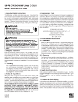
CFM deliverd against External Static Pressure
Model Speed
NOTE: Assumes dry coil with filter in place; SCFM correction for wet coil = 4% (208V/240V)
0.1" 0.2" 0.3" 0.4" 0.5"
High 1155 1090 1025 950 895
ARPF18241* Med. 940 890 860 815 755
Low 695 665 650 610 550
High 1135 1085 1025 965 915
ARPF19311* Med. 860 825 780 750 680
Low 600 570 545 500 465
High 1385 1315 1240 1155 1065
ARPF30301* Med. 1340 1290 1230 1140 1050
Low 1075 1030 980 910 840
High 1310 1240 1155 1090 1020
ARPF36361* Med. 1270 1210 1140 1075 980
Low 1045 1005 955 885 805
High 1700 1660 1625 1545 1505
ARPF36421* Med. 1500 1440 1400 1350 1345
Low 1330 1300 1250 1230 1220
High 2065 2000 1925 1860 1780
ARPF37431* Med. 1685 1635 1550 1470 1410
Low 1490 1425 1345 1280 1205
High 2150 2120 2070 2000 1940
ARPF48601* Med. 1940 1930 1905 1860 1790
Low 1610 1600 1590 1575 1550
High 2150 2105 2040 1970 1880
ARPF49611* Med. 1960 1935 1895 1825 1750
Low 1670 1625 1585 1525 1455
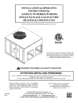
CFM deliverd against External Static Pressure
Model Speed
NOTE: Assumes dry coil with filter in place; SCFM correction for wet coil = 4% (208V/240V)
0.1" 0.2" 0.3" 0.4" 0.5"
High 1,155 1,090 1,025 950 895
ADPF18241/16 Med. 940 890 860 815 755
Low 695 665 650 610 550
High 1,700 1,660 1,625 1,545 1,505
ADPF30421/16 Med. 1,500 1,440 1,400 1,350 1,345
Low 1,370 1,300 1,250 1,230 1,220
High 2,150 2,120 2,070 2,000 1,940
ADPF48601/16 Med. 1,940 1,930 1,905 1,860 1,790
Low 1,610 1,600 1,590 1,575 1,550
CFM deliverd against External Static Pressure
Model Speed
NOTE: Assumes dry coil with filter in place; SCFM correction for wet coil = 4% (208V/240V)
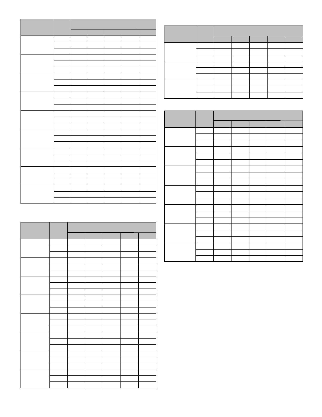
0.1" 0.2" 0.3" 0.4" 0.5"
High 1155 1090 1025 950 895
ATUF182416 Med. 875 830 790 750 715
Low 640 610 570 535 490
High 1135 1085 1025 965 915
ATUF193116 Med. 860 825 780 750 680
Low 600 570 545 500 465
High 1455 1385 1330 1205 1090
ATUF303016 Med. 1340 1290 1230 1140 1050
Low 1075 1030 980 910 840
High 1345 1290 1230 1150 1070
ATUF363616 Med. 1270 1210 1140 1075 980
Low 1045 1005 955 885 805
High 1700 1680 1645 1610 1535
ATUF364216 Med. 1500 1480 1440 1380 1325
Low 135 1320 1275 1230 1195
High 2065 2000 1925 1860 1780
ARUF374316
Med. 1685 1635 1550 1470 1410
Low 1490 1425 1345 1280 1205
High 2135 2080 1985 1900 1805
ATUF486016
Med. 1975 1935 1875 1775 1675
Low 1715 1670 1650 1590 1530
CFM deliverd against External Static Pressure
Model Speed
NOTE: Assumes dry coil with filter in place; SCFM correction for wet coil = 4% (208V/240V)
ASPF Motor
The ASPF air handler features an energy efficient blower
motor. The motor is a constant torque motor with very low
power consumption. The motor is energized by 24 VAC. Ad-
just the CFM by changing the 24 VAC leads to the desired
speed on the terminal block.
The ASPF motor blower speed is programmed to deliver ad-
equate airflow at rated external static pressure and with 60
second off time delay. For details, refer to the specification
sheet applicable to your model.
CFM Delivery
Table 13 shows the CFM speed tap settings for the ASPF.
Thermostats
NOTE: Second Stage heat can be accomplished by multi-
stage heating thermostat or the addition of an outdoor